
Service Manual
Page 74
... key. F Note: When YES or NO is selected on display 3 above is selected while display 2 above . 74 PDP-434CMX 1 2 3 4 C 1 2 3 4 5 6 7 8 9 10 11 12 13 14 15 16 17 ... 14 15 16 • Move the cursor to NO, and press the SET key. The data in the backup ROM) 2 Downloading the data for the panel.) • Move the cursor to YES and press the SET key. RGB - 4MX 3 4 D I G I N 1 -G3 2 - RGB - 4MX 3 4 D I G I T A L... copy to the DIGITAL VIDEO Assy. (When a new DIGITAL VIDEO Assy has been mounted, it are temporarily stored in the backup ROM then A are written on the new...
... key. F Note: When YES or NO is selected on display 3 above is selected while display 2 above . 74 PDP-434CMX 1 2 3 4 C 1 2 3 4 5 6 7 8 9 10 11 12 13 14 15 16 17 ... 14 15 16 • Move the cursor to NO, and press the SET key. The data in the backup ROM) 2 Downloading the data for the panel.) • Move the cursor to YES and press the SET key. RGB - 4MX 3 4 D I G I N 1 -G3 2 - RGB - 4MX 3 4 D I G I T A L... copy to the DIGITAL VIDEO Assy. (When a new DIGITAL VIDEO Assy has been mounted, it are temporarily stored in the backup ROM then A are written on the new...

Service Manual
Page 107
... (area A) • Margin adjustment values (Vsus, Vofset) • Power upper-limit adjustment value (ABL) • PANEL white-balance adjustment values (PANEL-R HIGH, PANEL-G HIGH, PANEL-B HIGH, PANEL-R LOW, PANEL-G LOW, PANEL-B LOW) • Drive waveform adjustment values (X-SUS-U1, X-SUS-U2, X-SUS-D1, X-SUS-D2, Y-SUS-U1...Area B of the RGB Assy of Unit 2, overwriting the data necessary for backup. A When the DIGITAL VIDEO Assy is mounted on the main unit. F PDP-434CMX 107 5 6 7 8 Part of keywords is replaced with an Assy for service Data in the EEPROM on the DIGITAL...
... (area A) • Margin adjustment values (Vsus, Vofset) • Power upper-limit adjustment value (ABL) • PANEL white-balance adjustment values (PANEL-R HIGH, PANEL-G HIGH, PANEL-B HIGH, PANEL-R LOW, PANEL-G LOW, PANEL-B LOW) • Drive waveform adjustment values (X-SUS-U1, X-SUS-U2, X-SUS-D1, X-SUS-D2, Y-SUS-U1...Area B of the RGB Assy of Unit 2, overwriting the data necessary for backup. A When the DIGITAL VIDEO Assy is mounted on the main unit. F PDP-434CMX 107 5 6 7 8 Part of keywords is replaced with an Assy for service Data in the EEPROM on the DIGITAL...

Service Manual
Page 108
...(see "6.6 Command Description"). • Shifting to Table 1: Send the "F60" command. Note 2: Readjustment of the main unit is mounted on the DIGITAL VIDEO Assy for the DIGITAL VIDEO Assy to 256. Note 4: If readjustment of the main unit is performed properly. Obtaining... the adjustment values: Send the "GPW" command. • Shifting to Table 2: Send the "F75" command. F 108 PDP-434CMX 1 2 3 4 Obtaining the adjustment values: Send the "GPW" command. • Shifting to Table 2: Send the "M51" and "F75" commands. 1 2 3...
...(see "6.6 Command Description"). • Shifting to Table 1: Send the "F60" command. Note 2: Readjustment of the main unit is mounted on the DIGITAL VIDEO Assy for the DIGITAL VIDEO Assy to 256. Note 4: If readjustment of the main unit is performed properly. Obtaining... the adjustment values: Send the "GPW" command. • Shifting to Table 2: Send the "F75" command. F 108 PDP-434CMX 1 2 3 4 Obtaining the adjustment values: Send the "GPW" command. • Shifting to Table 2: Send the "M51" and "F75" commands. 1 2 3...
Service Manual
Page 153
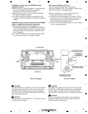
...mm) to 11/16 inch (18 mm) into the main unit from tipping over. 5 6 7 8 Installation using the optional PIONEER stand or Wall-mount installation of the unit installation bracket This unit has been designed with bolt holes for ÷ Please be sure to request installation or... inches (18 mm) Bolt b hole 1/2 inches (12 mm) to use of deterioration and dirt build cooperate when unpacking,moving, or installing the display. F PDP-434CMX 153 5 6 7 8 below . the attaching surface for both a holes and b holes. As a result, two or more locations above and the stand or...
...mm) to 11/16 inch (18 mm) into the main unit from tipping over. 5 6 7 8 Installation using the optional PIONEER stand or Wall-mount installation of the unit installation bracket This unit has been designed with bolt holes for ÷ Please be sure to request installation or... inches (18 mm) Bolt b hole 1/2 inches (12 mm) to use of deterioration and dirt build cooperate when unpacking,moving, or installing the display. F PDP-434CMX 153 5 6 7 8 below . the attaching surface for both a holes and b holes. As a result, two or more locations above and the stand or...


