Service Manual
Page 1
..., Tokyo 153-8654, Japan PIONEER ELECTRONICS (USA) INC. Order No. Box 1760, Long Beach, CA 90801-1760, U.S.A. PIONEER EUROPE NV Haven 1087, Keetberglaan 1, 9120 Melsele, Belgium PIONEER ELECTRONICS ASIACENTRE PTE. ARP3198 PDP-434CMX PLASMA DISPLAY PDP-434CMX PDP-43MXE1 PDP-43MXE1-S THIS MANUAL IS APPLICABLE TO THE FOLLOWING MODEL(S) AND TYPE(S). Remarks PDP-434CMX, PDP-43MXE1 PDP-43MXE1-S ARP3199 SCHEMATIC DIAGRAM, PCB CONNECTION DIAGRAM Refer to "Important symbols for video card. Order No. LTD...
..., Tokyo 153-8654, Japan PIONEER ELECTRONICS (USA) INC. Order No. Box 1760, Long Beach, CA 90801-1760, U.S.A. PIONEER EUROPE NV Haven 1087, Keetberglaan 1, 9120 Melsele, Belgium PIONEER ELECTRONICS ASIACENTRE PTE. ARP3198 PDP-434CMX PLASMA DISPLAY PDP-434CMX PDP-43MXE1 PDP-43MXE1-S THIS MANUAL IS APPLICABLE TO THE FOLLOWING MODEL(S) AND TYPE(S). Remarks PDP-434CMX, PDP-43MXE1 PDP-43MXE1-S ARP3199 SCHEMATIC DIAGRAM, PCB CONNECTION DIAGRAM Refer to "Important symbols for video card. Order No. LTD...
Service Manual
Page 2
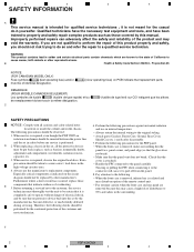
... components as barriers, nonmetallic knobs, adjustment and compartment covershields, isolation resistorcapacitor, etc. 3. 1 2 3 4 SAFETY INFORMATION A This service manual is radiated and may disturb reception of the remote control unit. • Pay extreme caution when the front case and rear panel are removed because this may void the warranty. Before returning a serviced set to the customer, the service technician must be sure that...
... components as barriers, nonmetallic knobs, adjustment and compartment covershields, isolation resistorcapacitor, etc. 3. 1 2 3 4 SAFETY INFORMATION A This service manual is radiated and may disturb reception of the remote control unit. • Pay extreme caution when the front case and rear panel are removed because this may void the warranty. Before returning a serviced set to the customer, the service technician must be sure that...
Service Manual
Page 3
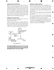
... tester (DC 500V), connect one , shown in the parts list in this Service Manual. Electrical components having such features are issued from an AC power source, place a jumper across the two plug prongs. C Device under review and new instructions are identified by marking with plug reversed (Using AC adapter Earth ground D plug as the PIONEER recommended replacement one lead to the jumpered AC plug and touch the...
... tester (DC 500V), connect one , shown in the parts list in this Service Manual. Electrical components having such features are issued from an AC power source, place a jumper across the two plug prongs. C Device under review and new instructions are identified by marking with plug reversed (Using AC adapter Earth ground D plug as the PIONEER recommended replacement one lead to the jumpered AC plug and touch the...
Service Manual
Page 5
... and mirrors used . C D E F PDP-434CMX 5 5 6 7 8 5 6 7 8 [ Important symbols for good services ] In this manual, adjustments should be performed. 3. Lubricants, glues, and replacement parts Appropriately applying grease or glue can maintain the product performances. Shipping mode and shipping screws To protect the product from damages or failures that adjustments, settings or cleaning should be sure to proper portions by following the instructions in projection monitors, and...
... and mirrors used . C D E F PDP-434CMX 5 5 6 7 8 5 6 7 8 [ Important symbols for good services ] In this manual, adjustments should be performed. 3. Lubricants, glues, and replacement parts Appropriately applying grease or glue can maintain the product performances. Shipping mode and shipping screws To protect the product from damages or failures that adjustments, settings or cleaning should be sure to proper portions by following the instructions in projection monitors, and...

Service Manual
Page 6
PANEL FACILITIES ...148 E F 6 PDP-434CMX 1 2 3 4 ADJUSTMENT ...62 6.1 ADJUSTMENT REQUIRED WHEN THE SET IS REPAIRED OR REPLACED 62 6.2 SERVICE FACTORY MODE ...63 6.3 HOW TO ENTER FACTORY MODE ...64 6.4 COMMAND DESCRIPTION...87 7. PCB CONNECTION DIAGRAM (Refer to "Service Manual: ARP3199 24 3.1 BLOCK DIAGRAM ...24 B 3.1.1 OVERALL BLOCK DIAGRAM (1/2) ...24 3.1.2 OVERALL BLOCK DIAGRAM (2/2) ...26 3.1.3 SIGNAL ROUTE ...28 3.1.4 43 Y DRIVE ASSY ...29 3.1.5 43 X DRIVE ASSY ...30 3.1.6 DIGITAL VIDEO ASSY...31 3.1.7 AV I/O ASSY ...32 3.1.8 RGB ASSY ...33 3.1.9 AUDIO...
PANEL FACILITIES ...148 E F 6 PDP-434CMX 1 2 3 4 ADJUSTMENT ...62 6.1 ADJUSTMENT REQUIRED WHEN THE SET IS REPAIRED OR REPLACED 62 6.2 SERVICE FACTORY MODE ...63 6.3 HOW TO ENTER FACTORY MODE ...64 6.4 COMMAND DESCRIPTION...87 7. PCB CONNECTION DIAGRAM (Refer to "Service Manual: ARP3199 24 3.1 BLOCK DIAGRAM ...24 B 3.1.1 OVERALL BLOCK DIAGRAM (1/2) ...24 3.1.2 OVERALL BLOCK DIAGRAM (2/2) ...26 3.1.3 SIGNAL ROUTE ...28 3.1.4 43 Y DRIVE ASSY ...29 3.1.5 43 X DRIVE ASSY ...30 3.1.6 DIGITAL VIDEO ASSY...31 3.1.7 AV I/O ASSY ...32 3.1.8 RGB ASSY ...33 3.1.9 AUDIO...
Service Manual
Page 7
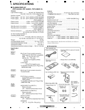
...) Remote Control Unit Holder (AMR3268) DVI-D 24-pin connector Digital RGB signal (DVI compliant TMDS signal) *Compatible with Microsoft "Plug & Play" (VESA DDC 2B) Binder Assy (AEC1758) PDP-43MXE1, E PDP-43MXE1-S Screw Set (AXX1060) Only AUDIO INPUT (for INPUT 1) Stereo mini jack Speed Clamp (×2) Washer (×2) (WB80FZB) Ferrite Core (ATX1039) L/R ... 500mVrms/more than 5 kΩ F SPEAKER L/R ... 8 - 16 Ω/7W +7W (at 8 Ω) PDP-434CMX 7 5 6 7 8 SPECIFICATIONS PLASMA DISPLAY (PDP-434CMX, PDP-43MXE1, PDP-43MXE1-S) General Light emission panel 43-inch...
...) Remote Control Unit Holder (AMR3268) DVI-D 24-pin connector Digital RGB signal (DVI compliant TMDS signal) *Compatible with Microsoft "Plug & Play" (VESA DDC 2B) Binder Assy (AEC1758) PDP-43MXE1, E PDP-43MXE1-S Screw Set (AXX1060) Only AUDIO INPUT (for INPUT 1) Stereo mini jack Speed Clamp (×2) Washer (×2) (WB80FZB) Ferrite Core (ATX1039) L/R ... 500mVrms/more than 5 kΩ F SPEAKER L/R ... 8 - 16 Ω/7W +7W (at 8 Ω) PDP-434CMX 7 5 6 7 8 SPECIFICATIONS PLASMA DISPLAY (PDP-434CMX, PDP-43MXE1, PDP-43MXE1-S) General Light emission panel 43-inch...

Service Manual
Page 62
... adjusted to restore the original settings. 3. DIGITAL VIDEO Assy No adjustment required 43 X DRIVE Assy 43 Y DRIVE Assy E AV I /O Assy C RGB Assy No adjustment required No adjustment required VIDEO SLOT Assy No adjustment required Other assemblies No adjustment required Service Panel VSUS and VOFS voltage setup, Panel WB check When any of the following assemblies is replaced D POWER SUPPLY Unit The assembly must be stored in case you need to its best...
... adjusted to restore the original settings. 3. DIGITAL VIDEO Assy No adjustment required 43 X DRIVE Assy 43 Y DRIVE Assy E AV I /O Assy C RGB Assy No adjustment required No adjustment required VIDEO SLOT Assy No adjustment required Other assemblies No adjustment required Service Panel VSUS and VOFS voltage setup, Panel WB check When any of the following assemblies is replaced D POWER SUPPLY Unit The assembly must be stored in case you need to its best...

Service Manual
Page 65
... screen/Sub screen change MAIN SUB E F PDP-434CMX 65 5 6 7 8 Setting data for Integrator mode Setting data for Integrator mode will become that of the keys on the display. C • Although adjustment data for Integrator mode are stored in memory, they are B not reflected on the display. • Although user's adjustment data for display are stored in memory, display adjustment data are reset to the default settings. • Screen size and sound volume reflect user settings. • The COLOR DECODING and SIGNAL FORMAT settings...
... screen/Sub screen change MAIN SUB E F PDP-434CMX 65 5 6 7 8 Setting data for Integrator mode Setting data for Integrator mode will become that of the keys on the display. C • Although adjustment data for Integrator mode are stored in memory, they are B not reflected on the display. • Although user's adjustment data for display are stored in memory, display adjustment data are reset to the default settings. • Screen size and sound volume reflect user settings. • The COLOR DECODING and SIGNAL FORMAT settings...

Service Manual
Page 76
... on the signal resolution, input signal format, and main/sub screen. E F Adjustment values to be stored in the EEPROM of the RGB (COMMON mode) Adjustment values differ depending on the input function and main/sub screen. Adjustment values to be Switched RGB ADC All R, G, and B signals Color difference ADC All color-difference signals • For adjustment according to the above tables, input video signals to INPUT 5 to switch to change the RGB/color-difference signal setting then perform adjustment. •...
... on the signal resolution, input signal format, and main/sub screen. E F Adjustment values to be stored in the EEPROM of the RGB (COMMON mode) Adjustment values differ depending on the input function and main/sub screen. Adjustment values to be Switched RGB ADC All R, G, and B signals Color difference ADC All color-difference signals • For adjustment according to the above tables, input video signals to INPUT 5 to switch to change the RGB/color-difference signal setting then perform adjustment. •...

Service Manual
Page 84
1 2 3 4 1. Multi screen OFF FUNCTIONAL LOCK LOCK OFF Menu setting PICTURE SCREEN Default setting for all adjustment items For each input function One of the factory-preset signals is output, based on the results of signal-type detection (SIG-MODE) for the input function. OFF/ 01H00M ORBITER OFF MASK CONTROL ON AUTO SET UP MODE INACTIVE AUTO FUNCTION OFF AUDIO OUT FIXED ∗ 720-PC selectable only with video card is inserted One of the factory-preset signals is output, based on the...
1 2 3 4 1. Multi screen OFF FUNCTIONAL LOCK LOCK OFF Menu setting PICTURE SCREEN Default setting for all adjustment items For each input function One of the factory-preset signals is output, based on the results of signal-type detection (SIG-MODE) for the input function. OFF/ 01H00M ORBITER OFF MASK CONTROL ON AUTO SET UP MODE INACTIVE AUTO FUNCTION OFF AUDIO OUT FIXED ∗ 720-PC selectable only with video card is inserted One of the factory-preset signals is output, based on the...

Service Manual
Page 85
... FAN CONTROL AUTO COLOR MODE NORMAL PRO USE OFF/OFF/DISABLE/ MOTION C FRC MODE1 Factory PATTERN MASK OFF FULL MASK OFF 232C EDIT WRITE MODE LOUDNESS DISABLE OFF D E F PDP-434CMX 85 5 6 7 8 SET SCREEN MASK 00H10M/00H30M/WHITE/ 00H10M/INV.1/1 OFF SIDE MASK NORMAL/80/80/80 B 2x2 MODE OFF/UP LEFT/NORMAL MIRROR MODE OFF BAUD RATE 9600BPS ID NO. BRT. 5 6 7 8 Item (operation) Factory setting Remarks Integrator PICTURE Default setting...
... FAN CONTROL AUTO COLOR MODE NORMAL PRO USE OFF/OFF/DISABLE/ MOTION C FRC MODE1 Factory PATTERN MASK OFF FULL MASK OFF 232C EDIT WRITE MODE LOUDNESS DISABLE OFF D E F PDP-434CMX 85 5 6 7 8 SET SCREEN MASK 00H10M/00H30M/WHITE/ 00H10M/INV.1/1 OFF SIDE MASK NORMAL/80/80/80 B 2x2 MODE OFF/UP LEFT/NORMAL MIRROR MODE OFF BAUD RATE 9600BPS ID NO. BRT. 5 6 7 8 Item (operation) Factory setting Remarks Integrator PICTURE Default setting...

Service Manual
Page 87
.... F Not.3: During Standby or full-screen display, values stored in Factory or Normal mode. Reply data format B STX Received command Transmission data • • • Transmission data CS (2byte) ETX (3byte) Example: [02] GAS 2 • • • 0 97 [03] GST: GET STATUS Order 1 Display data 2 Power data Data 3 Input function data (main) 4 Input function data (sub) 5 Screen size data 6 Two-screen indication 7 FUNCTIONAL LOCK data 8 Dummy...
.... F Not.3: During Standby or full-screen display, values stored in Factory or Normal mode. Reply data format B STX Received command Transmission data • • • Transmission data CS (2byte) ETX (3byte) Example: [02] GAS 2 • • • 0 97 [03] GST: GET STATUS Order 1 Display data 2 Power data Data 3 Input function data (main) 4 Input function data (sub) 5 Screen size data 6 Two-screen indication 7 FUNCTIONAL LOCK data 8 Dummy...

Service Manual
Page 93
... usually displayed when the power is turned on FCA FCM Turning fan roll control to auto Maximizing the fan roll control FST FXO Executing FINAL SETUP Selecting audio output fixing [G] GAJ Obtaining the adjustment values for positions are not stored in memory in force, the duration of auto setup The values for the panel GMM Switching the gamma ? 000 007 GNG Obtaining the shutdown information F PDP-434CMX 93 5 6 7 8 5 6 7 8 LIST OF...
... usually displayed when the power is turned on FCA FCM Turning fan roll control to auto Maximizing the fan roll control FST FXO Executing FINAL SETUP Selecting audio output fixing [G] GAJ Obtaining the adjustment values for positions are not stored in memory in force, the duration of auto setup The values for the panel GMM Switching the gamma ? 000 007 GNG Obtaining the shutdown information F PDP-434CMX 93 5 6 7 8 5 6 7 8 LIST OF...

Service Manual
Page 102
... connected. 4 4 Check if the cable is disconnected or not securely connected. 14 Communication failure in IF AV I /O Defective IF microcomputer No power (The LED remains lit in red and does not light in green.) RGB Defective main microcomputer Key input not effective Disconnection of cable Remote control unit not effective IR RECEIVE Disconnection of cable Defective IR receiver section DIGITAL VIDEO Defective IC4 Abnormal screen (Data of communication line...
... connected. 4 4 Check if the cable is disconnected or not securely connected. 14 Communication failure in IF AV I /O Defective IF microcomputer No power (The LED remains lit in red and does not light in green.) RGB Defective main microcomputer Key input not effective Disconnection of cable Remote control unit not effective IR RECEIVE Disconnection of cable Defective IR receiver section DIGITAL VIDEO Defective IC4 Abnormal screen (Data of communication line...

Service Manual
Page 117
..., control for communication path switch Setting pin for flash rewriting mode (pull-down) IC4 forced reset Enable for IC4 communication Busy input for IC4 communication Communication request from the IC4 Setting pin for flash rewriting mode (pull-up ) (Interruption) Remote control signal input (in the panel unit) (Interruption) Key signal input (in the POWER SUPPLY Unit PD signal of DC-DC converter NC pin NC pin V. 5 6 7 M30626FHPGP-P (DIGITAL VIDEO ASSY : IC5201) • PDP...
..., control for communication path switch Setting pin for flash rewriting mode (pull-down) IC4 forced reset Enable for IC4 communication Busy input for IC4 communication Communication request from the IC4 Setting pin for flash rewriting mode (pull-up ) (Interruption) Remote control signal input (in the panel unit) (Interruption) Key signal input (in the POWER SUPPLY Unit PD signal of DC-DC converter NC pin NC pin V. 5 6 7 M30626FHPGP-P (DIGITAL VIDEO ASSY : IC5201) • PDP...

Service Manual
Page 118
... TEMP 93 MODE 94 AVSS 95 MODEL 96 VREF 97 AVCC 98 NC 99 NC 100 AMG_MD F 118 1 2 3 4 Function Driving OFF Power ON control output Power ON control input MDR connection detection Rear case open detection NC pin Panel mute PC/VIDEO dither switch (panel module exclusive use) NC pin Power supply = STB 3.3V PD detection GND Vh power decrease PD Y drive PD signal Y drive PD signal PD signal of Y drive...
... TEMP 93 MODE 94 AVSS 95 MODEL 96 VREF 97 AVCC 98 NC 99 NC 100 AMG_MD F 118 1 2 3 4 Function Driving OFF Power ON control output Power ON control input MDR connection detection Rear case open detection NC pin Panel mute PC/VIDEO dither switch (panel module exclusive use) NC pin Power supply = STB 3.3V PD detection GND Vh power decrease PD Y drive PD signal Y drive PD signal PD signal of Y drive...

Service Manual
Page 148
... remote control toward the remote sensor to open and close the on the main unit 8 INPUT button Press to select the input. 9 MENU button Press to operate the unit . Operation panel on -screen menu. D 3 Ambient light sensor This sensor measures the level of handle attachment, but the handles themselves are used for adjusting the sound volume. Lights green when the plasma display is set status. 6 Handles The plasma displays PDP-504CMX/ PDP-50MXE1/ PDP-50MXE1-S and PDP-434CMX/ PDP-43MXE1/ PDP...
... remote control toward the remote sensor to open and close the on the main unit 8 INPUT button Press to select the input. 9 MENU button Press to operate the unit . Operation panel on -screen menu. D 3 Ambient light sensor This sensor measures the level of handle attachment, but the handles themselves are used for adjusting the sound volume. Lights green when the plasma display is set status. 6 Handles The plasma displays PDP-504CMX/ PDP-50MXE1/ PDP-50MXE1-S and PDP-434CMX/ PDP-43MXE1/ PDP...

Service Manual
Page 149
... OUT D-Sub INPUT1 AUDIO DIGITAL RGB DVI-D INPUT2 OUTPUT AUDIO AUDIO 1 2 3 4 5 6 7 89 C Plasma Display Section The plasma display is installed. 5 ANALOG RGB OUT (INPUT1) (mini D-sub 15 pin) Use the ANALOG RGB OUT (INPUT1) terminal to output the video signal to an external monitor or other component. When this connector without first consulting your Pioneer installation technician. Connect a speaker that the connection made corresponds to the format of video input connectors are used in standby mode. 6 AUDIO (INPUT1) (Stereo...
... OUT D-Sub INPUT1 AUDIO DIGITAL RGB DVI-D INPUT2 OUTPUT AUDIO AUDIO 1 2 3 4 5 6 7 89 C Plasma Display Section The plasma display is installed. 5 ANALOG RGB OUT (INPUT1) (mini D-sub 15 pin) Use the ANALOG RGB OUT (INPUT1) terminal to output the video signal to an external monitor or other component. When this connector without first consulting your Pioneer installation technician. Connect a speaker that the connection made corresponds to the format of video input connectors are used in standby mode. 6 AUDIO (INPUT1) (Stereo...

Service Manual
Page 151
... button During multi-screen display, use this button to move the position of the screen. Usage of cursor buttons within operations is attached to the unit. 0 3 MENU button Press to open and close the on-screen menu. - 4 ADJUST ( 5 / ∞ / 3 / 2 ) buttons B Use to navigate menu screens and to adjust various settings on the unit. 6 SUB INPUT button During multi-screen display, use this button to put the unit in operation or standby mode. - 5 REMOTE CONTROL UNIT 1 2 3 4 5 6 7 8 6 7 8 A 1 SCREEN SIZE button Press to select the screen size. 2 INPUT buttons...
... button During multi-screen display, use this button to move the position of the screen. Usage of cursor buttons within operations is attached to the unit. 0 3 MENU button Press to open and close the on-screen menu. - 4 ADJUST ( 5 / ∞ / 3 / 2 ) buttons B Use to navigate menu screens and to adjust various settings on the unit. 6 SUB INPUT button During multi-screen display, use this button to put the unit in operation or standby mode. - 5 REMOTE CONTROL UNIT 1 2 3 4 5 6 7 8 6 7 8 A 1 SCREEN SIZE button Press to select the screen size. 2 INPUT buttons...
Service Manual
Page 153
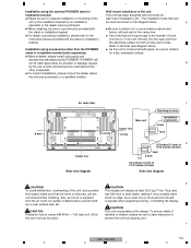
... view diagram below . Installation using parts and accessories manufactured by an installation be used .) prevent the unit from the air vents, be sure to take measures to this unit is expelled stood on rear surface wall, etc.. As a result, two or more locations above and the stand or installation bracket. F PDP-434CMX 153 5 6 7 8 a hole Bolt 1/2 inches (12 mm) to D 11/16 inches (18 mm) Bolt b hole 1/2 inches (12 mm) to install...
... view diagram below . Installation using parts and accessories manufactured by an installation be used .) prevent the unit from the air vents, be sure to take measures to this unit is expelled stood on rear surface wall, etc.. As a result, two or more locations above and the stand or installation bracket. F PDP-434CMX 153 5 6 7 8 a hole Bolt 1/2 inches (12 mm) to D 11/16 inches (18 mm) Bolt b hole 1/2 inches (12 mm) to install...


