Owner's Manual
Page 3
... used to connect the unit to provide reasonable protection against harmful interference in a secure area. Product Name: Plasma Display System (Plasma Display) (Media Receiver) Model Number: PDP-5045HD PDP-4345HD (PDP-504PU) (PDP-434PU) (PDP-R05U) (PDP-R05U) Product Category: Class B Personal Computers & Peripherals Responsible Party Name: PIONEER ELECTRONICS (USA), INC., Customer Support Div. WARNING: Be sure to operate the equipment. [For Canadian model] This Class B digital apparatus complies with the instructions...
... used to connect the unit to provide reasonable protection against harmful interference in a secure area. Product Name: Plasma Display System (Plasma Display) (Media Receiver) Model Number: PDP-5045HD PDP-4345HD (PDP-504PU) (PDP-434PU) (PDP-R05U) (PDP-R05U) Product Category: Class B Personal Computers & Peripherals Responsible Party Name: PIONEER ELECTRONICS (USA), INC., Customer Support Div. WARNING: Be sure to operate the equipment. [For Canadian model] This Class B digital apparatus complies with the instructions...
Owner's Manual
Page 4
.../UHF antennas 21 Switching between antenna A and B 22 Inserting the cable card 22 Connecting the power cord 23 07 Basic Operations Turning on the power 24 Turning off the power 24 Watching TV channels 25 Selecting the antenna 25 Changing channels 25 Changing the volume and sound 26 Viewing a channel banner 26 Using the POD service 27 Changing the language 27 Setting MTS/SAP mode 27 Using the multiscreen functions 28 Splitting the screen 28 Freezing images 29 08 Menu Setup Menu...
.../UHF antennas 21 Switching between antenna A and B 22 Inserting the cable card 22 Connecting the power cord 23 07 Basic Operations Turning on the power 24 Turning off the power 24 Watching TV channels 25 Selecting the antenna 25 Changing channels 25 Changing the volume and sound 26 Viewing a channel banner 26 Using the POD service 27 Changing the language 27 Setting MTS/SAP mode 27 Using the multiscreen functions 28 Splitting the screen 28 Freezing images 29 08 Menu Setup Menu...
Owner's Manual
Page 5
... mode only 45 Adjusting image positions and clock manually (PC mode only 45 Selecting a screen size 46 Changing the brightness at both sides of the screen (Side Mask 47 Language setting 47 11 Timer Presetting Presetting TV programs using the timer 48 Priority rules for overlapped presettings 49 12 Enjoying through External Equipment Watching a DVD image 50 Connecting a DVD player 50 Displaying a DVD image 50 Watching a VCR image 50 Connecting a VCR 50 Displaying a VCR image 50 Using HDMI Input 51 Connecting HDMI...
... mode only 45 Adjusting image positions and clock manually (PC mode only 45 Selecting a screen size 46 Changing the brightness at both sides of the screen (Side Mask 47 Language setting 47 11 Timer Presetting Presetting TV programs using the timer 48 Priority rules for overlapped presettings 49 12 Enjoying through External Equipment Watching a DVD image 50 Connecting a DVD player 50 Displaying a DVD image 50 Watching a VCR image 50 Connecting a VCR 50 Displaying a VCR image 50 Using HDMI Input 51 Connecting HDMI...
Owner's Manual
Page 6
... of time. • When playing a game, the "GAME" mode setting within "AV Selection" is strongly recommended. Using the unit without proper ventilation may result in the "WIDE" or "FULL" screen setting for a prolonged period. To achieve images of the Media Receiver. • Do not reverse the product. To enjoy beautiful and bright images on the sides and rear of the Pioneer PDP-5045HD/PDP-4345HD Plasma Display System will automatically power...
... of time. • When playing a game, the "GAME" mode setting within "AV Selection" is strongly recommended. Using the unit without proper ventilation may result in the "WIDE" or "FULL" screen setting for a prolonged period. To achieve images of the Media Receiver. • Do not reverse the product. To enjoy beautiful and bright images on the sides and rear of the Pioneer PDP-5045HD/PDP-4345HD Plasma Display System will automatically power...
Owner's Manual
Page 8
.... 2. Power cord protection-The power cords must be routed properly to follow the manufacturer's instructions. When the power cord or plug is damaged. Improper adjustment of the Plasma Display to prevent potential danger, please observe the following precautions carefully before installing the speakers. 23. When the product displays an abnormal condition. To ensure your safety and prolong the service life of time. Attachments-Do not use the...
.... 2. Power cord protection-The power cords must be routed properly to follow the manufacturer's instructions. When the power cord or plug is damaged. Improper adjustment of the Plasma Display to prevent potential danger, please observe the following precautions carefully before installing the speakers. 23. When the product displays an abnormal condition. To ensure your safety and prolong the service life of time. Attachments-Do not use the...
Owner's Manual
Page 22
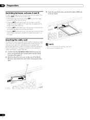
... R-AUDIO-L VIDEO R-AUDIO-L (TS) VIDEO S400 R-AUDIO-L COMPCOBN/PEBNT CVIRD/EPOR Y S-VIDEO R-AUDIO-L INPUT 3 Y CB/PB CR/PR INPUT 1 H • Be sure to a TV image. 06 Preparation Switching between antenna A and B To watch broadcasts via the two antennas, you to use the POD service provided by pressing ANT on the rear of the Media Receiver, and remove the cover while releasing the tab's latch. 3 Insert the specified cable card into the Cable CARD...
... R-AUDIO-L VIDEO R-AUDIO-L (TS) VIDEO S400 R-AUDIO-L COMPCOBN/PEBNT CVIRD/EPOR Y S-VIDEO R-AUDIO-L INPUT 3 Y CB/PB CR/PR INPUT 1 H • Be sure to a TV image. 06 Preparation Switching between antenna A and B To watch broadcasts via the two antennas, you to use the POD service provided by pressing ANT on the rear of the Media Receiver, and remove the cover while releasing the tab's latch. 3 Insert the specified cable card into the Cable CARD...
Owner's Manual
Page 23
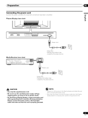
Plasma Display (rear view) English Power cord Media Receiver (rear view) IN OUT CONTROL VCR CONTROL IN ANTENNA B ANTENNA/ CABLE A IN Cable CARD S-VIDEO INPUT 2 INPUT 2 VIDEO R-AUDIO-L DIGITAL OUT OPTICAL (TS) S400 VIDEO INPUT 1 COMPONENT VIDEO R-AUDIO-L Y CB/PB CR/PR SERVICE ONLY OUT MONITOR OUT S-VIDEO VIDEO R-AUDIO-L S-VIDEO R-AUDIO-L IINNPPUUTT 33 Y CB/PB CR/PR INPUT 1 INPUT 3 HDMI ACACINILNET BLACK WHITE SYSTEM CABLE Noise filter Partially eliminates noise caused by the power source. • Use only the supplied power cord. • Be sure to a three-...
Plasma Display (rear view) English Power cord Media Receiver (rear view) IN OUT CONTROL VCR CONTROL IN ANTENNA B ANTENNA/ CABLE A IN Cable CARD S-VIDEO INPUT 2 INPUT 2 VIDEO R-AUDIO-L DIGITAL OUT OPTICAL (TS) S400 VIDEO INPUT 1 COMPONENT VIDEO R-AUDIO-L Y CB/PB CR/PR SERVICE ONLY OUT MONITOR OUT S-VIDEO VIDEO R-AUDIO-L S-VIDEO R-AUDIO-L IINNPPUUTT 33 Y CB/PB CR/PR INPUT 1 INPUT 3 HDMI ACACINILNET BLACK WHITE SYSTEM CABLE Noise filter Partially eliminates noise caused by the power source. • Use only the supplied power cord. • Be sure to a three-...
Owner's Manual
Page 24
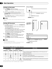
... remove the power cord from the power outlet. Plasma Display STANDBY indicator POWER ON indicator POWER button • In this manual, "system" means the Plasma Display Panel and Media Receiver. (right view) Turning off the power 1 Press TV on the remote control unit or STANDBY/ON on the Plasma Display. • The system enters the standby mode and the image on the screen disappears. • Both STANDBY indicators light up red. • It is in the standby mode. 2 Press POWER on the Media Receiver. • The STANDBY...
... remove the power cord from the power outlet. Plasma Display STANDBY indicator POWER ON indicator POWER button • In this manual, "system" means the Plasma Display Panel and Media Receiver. (right view) Turning off the power 1 Press TV on the remote control unit or STANDBY/ON on the Plasma Display. • The system enters the standby mode and the image on the screen disappears. • Both STANDBY indicators light up red. • It is in the standby mode. 2 Press POWER on the Media Receiver. • The STANDBY...

Owner's Manual
Page 27
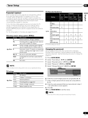
... determined by the cable TV company. STEREO mode SAP mode MONO mode STEREO SAP MONO • In each of useful information, using the Multi-channel Television Sound (MTS) function. • Stereo broadcasts You can use the POD service provided by the video source. See page 32. In this manual designate TV channels that are received through language setting is available when the channel or program is changed, you will hear...
... determined by the cable TV company. STEREO mode SAP mode MONO mode STEREO SAP MONO • In each of useful information, using the Multi-channel Television Sound (MTS) function. • Stereo broadcasts You can use the POD service provided by the video source. See page 32. In this manual designate TV channels that are received through language setting is available when the channel or program is changed, you will hear...
Owner's Manual
Page 33
...) Parental Control Password Password Change Password Clear Password xxxxxxxxxxxxxxxxxxxxx xxxxxxxxxxxxxxxxxxxxx xxxxxxxxxxxxxxxxxxxxx Home Menu Exit 6 Enter the current 4-digit password, using buttons 0 - 9. 7 Enter a 4-digit password to exit the menu. • Take a note of America (MPAA) and are provided by the Motion Picture Association of the newly set , using buttons 0 - 9. 8 Enter the same password that has now been superseded by parents, the Plasma Display shows nothing but a message. The Parental Control functions for television. Under...
...) Parental Control Password Password Change Password Clear Password xxxxxxxxxxxxxxxxxxxxx xxxxxxxxxxxxxxxxxxxxx xxxxxxxxxxxxxxxxxxxxx Home Menu Exit 6 Enter the current 4-digit password, using buttons 0 - 9. 7 Enter a 4-digit password to exit the menu. • Take a note of America (MPAA) and are provided by the Motion Picture Association of the newly set , using buttons 0 - 9. 8 Enter the same password that has now been superseded by parents, the Plasma Display shows nothing but a message. The Parental Control functions for television. Under...

Owner's Manual
Page 50
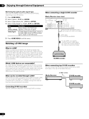
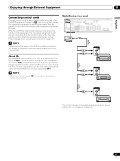
... instruction manual (DVD player, personal computer, etc.) carefully before making connections. Media Receiver (rear view) IN OUT VCR CONTROL CONTROL IN ANTENNA B ANTENNA/ CABLE A IN Cable CARD (TS) S400 DIGITAL OUT OPTICAL S-VIDEO INPUT 2 VIDEO R-AUDIO-L VIDEO INPUT 1 COMPONENT VIDEO R-AUDIO-L Y CB/PB CR/PR SERVICE ONLY OUT MONITOR OUT S-VIDEO VIDEO R-AUDIO-L S-VIDEO R-AUDIO-L IINNPUTT 33 Y CB/PB CR/PR INPUT 1 INPUT HDMI AV cable (commercially available) S-Video cable (commercially available) DVD player VCR Displaying a VCR image To watch a DVD image, press INPUT...
... instruction manual (DVD player, personal computer, etc.) carefully before making connections. Media Receiver (rear view) IN OUT VCR CONTROL CONTROL IN ANTENNA B ANTENNA/ CABLE A IN Cable CARD (TS) S400 DIGITAL OUT OPTICAL S-VIDEO INPUT 2 VIDEO R-AUDIO-L VIDEO INPUT 1 COMPONENT VIDEO R-AUDIO-L Y CB/PB CR/PR SERVICE ONLY OUT MONITOR OUT S-VIDEO VIDEO R-AUDIO-L S-VIDEO R-AUDIO-L IINNPUTT 33 Y CB/PB CR/PR INPUT 1 INPUT HDMI AV cable (commercially available) S-Video cable (commercially available) DVD player VCR Displaying a VCR image To watch a DVD image, press INPUT...

Owner's Manual
Page 51
.... (factory default) Enable Activates the HDMI terminal. 6 Press HOME MENU to exit the menu. Color-1 Digital Component Video signals (4:2:2) locked Color-2 Digital Component Video signals (4:4:4) locked Color-3 Digital RGB signals locked 6 Press HOME MENU to exit the menu. Before starting the menu, press INPUT 1 (or INPUT 3) on the remote control unit or press INPUT on the Plasma Display to be specified, check the operation manual that came with the connected equipment. Connecting HDMI equipment Media Receiver (rear view) DIGITAL OUT OPTICAL (TS) S400 VIDEO INPUT...
.... (factory default) Enable Activates the HDMI terminal. 6 Press HOME MENU to exit the menu. Color-1 Digital Component Video signals (4:2:2) locked Color-2 Digital Component Video signals (4:4:4) locked Color-3 Digital RGB signals locked 6 Press HOME MENU to exit the menu. Before starting the menu, press INPUT 1 (or INPUT 3) on the remote control unit or press INPUT on the Plasma Display to be specified, check the operation manual that came with the connected equipment. Connecting HDMI equipment Media Receiver (rear view) DIGITAL OUT OPTICAL (TS) S400 VIDEO INPUT...

Owner's Manual
Page 52
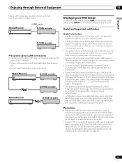
... Video, 2) S-Video, 3) Video. • Connect external equipment to be specified, check the operation manual that are checked for example, digital TV programs using the supplied VCR controller. Connect the VCR controller to the VCR control terminal on the rear of the game console or camcorder To watch an image coming from adversely affecting the quality of the Media Receiver, you connect recording equipment such as a VCR or DVD recorder to the MONITOR OUT...
... Video, 2) S-Video, 3) Video. • Connect external equipment to be specified, check the operation manual that are checked for example, digital TV programs using the supplied VCR controller. Connect the VCR controller to the VCR control terminal on the rear of the game console or camcorder To watch an image coming from adversely affecting the quality of the Media Receiver, you connect recording equipment such as a VCR or DVD recorder to the MONITOR OUT...

Owner's Manual
Page 53
...using the digital audio output terminal (optical), you need to the digital audio output terminal (optical) on a VCR or DVD recorder connected to be played in distorted images or noise. Selecting an external input source may result in high quality. Enjoying through External Equipment 12 English Connecting a recorder Media Receiver (rear view) IN OUT VCR CONTROL CONTROL IN ANTENNA B ANTENNA/ CABLE A IN Cable CARD (TS) S400 DIGITAL OUT OPTICAL S-VIDEO INPUT 2 VIDEO R-AUDIO-L VIDEO INPUT 1 COMPONENT VIDEO R-AUDIO-L Y CB/PB CR/PR SERVICE ONLY OUT MONITOR OUT S-VIDEO VIDEO...
...using the digital audio output terminal (optical), you need to the digital audio output terminal (optical) on a VCR or DVD recorder connected to be played in distorted images or noise. Selecting an external input source may result in high quality. Enjoying through External Equipment 12 English Connecting a recorder Media Receiver (rear view) IN OUT VCR CONTROL CONTROL IN ANTENNA B ANTENNA/ CABLE A IN Cable CARD (TS) S400 DIGITAL OUT OPTICAL S-VIDEO INPUT 2 VIDEO R-AUDIO-L VIDEO INPUT 1 COMPONENT VIDEO R-AUDIO-L Y CB/PB CR/PR SERVICE ONLY OUT MONITOR OUT S-VIDEO VIDEO...
Owner's Manual
Page 54
... can record only digital TV programs. You cannot record conventional TV channels nor contents coming from external input sources and personal computers. Media Receiver POWER REC DATA ON STANDBY TIMER ACQUISITION i.LINK cables D-VHS recorder D-VHS recorder 54 En For PCM encoded signals, outputs in the Dolby Digital format. Watching a D-VHS image What is a digital serial interface for the DIGITAL AUDIO output terminal (OPTICAL), depending on the rear of the Media Receiver. Connecting D-VHS recorders Use the i.LINK terminals...
... can record only digital TV programs. You cannot record conventional TV channels nor contents coming from external input sources and personal computers. Media Receiver POWER REC DATA ON STANDBY TIMER ACQUISITION i.LINK cables D-VHS recorder D-VHS recorder 54 En For PCM encoded signals, outputs in the Dolby Digital format. Watching a D-VHS image What is a digital serial interface for the DIGITAL AUDIO output terminal (OPTICAL), depending on the rear of the Media Receiver. Connecting D-VHS recorders Use the i.LINK terminals...
Owner's Manual
Page 55
... the remote control unit or press INPUT on page 57. 55 En See page 50. • This system supports the Digital Transmission Content Protection (DTCP) technology. Media Receiver POWER REC DATA ON STANDBY TIMER ACQUISITION i.LINK cable D-VHS recorder D-VHS recorder Precautions about i.LINK connections • Use S400 i.LINK cables that support i.LINK. It also may not allow video, audio, and other connected D-VHS recorder (not in image and sound...
... the remote control unit or press INPUT on page 57. 55 En See page 50. • This system supports the Digital Transmission Content Protection (DTCP) technology. Media Receiver POWER REC DATA ON STANDBY TIMER ACQUISITION i.LINK cable D-VHS recorder D-VHS recorder Precautions about i.LINK connections • Use S400 i.LINK cables that support i.LINK. It also may not allow video, audio, and other connected D-VHS recorder (not in image and sound...

Owner's Manual
Page 57
... none of the connected equipment has been supported for control, you press i.LINK again. The inserted tape cannot be operated. Operating the control panel screen The control panel screen appears when you to change the D-VHS recorder to be used for recording when this button, press / to select the desired model from the list, and then press ENTER. • If no display for VHS. 7 Appears...
... none of the connected equipment has been supported for control, you press i.LINK again. The inserted tape cannot be operated. Operating the control panel screen The control panel screen appears when you to change the D-VHS recorder to be used for recording when this button, press / to select the desired model from the list, and then press ENTER. • If no display for VHS. 7 Appears...
Owner's Manual
Page 59
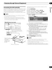
... specified recording equipment manufacture. 8 Press A to select "Yes, Store Setting". 9 Press HOME MENU to leave the VCR power on when presetting TV programs for recording; If you think it faces the VCR. Media Receiver (rear view) IN OUT VCR CONTROL CONTROL IN ANTENNA B ANTENNA/ CABLE A IN Cable CARD S-VIDEO INPUT 2 VIDEO R-AUDIO-L DIGITAL O OPTICA (TS) S400 VIDEO INPUT 1 COMPON R-AUDIO-L Y CB/ SERVICE ONLY OUT MONITOR OUT S-VIDEO VIDEO R-AUDIO-L S-VIDEO R-AUDIO-L IINNPUTT 33 Y CB/ (Once you correctly specify the manufacture of...
... specified recording equipment manufacture. 8 Press A to select "Yes, Store Setting". 9 Press HOME MENU to leave the VCR power on when presetting TV programs for recording; If you think it faces the VCR. Media Receiver (rear view) IN OUT VCR CONTROL CONTROL IN ANTENNA B ANTENNA/ CABLE A IN Cable CARD S-VIDEO INPUT 2 VIDEO R-AUDIO-L DIGITAL O OPTICA (TS) S400 VIDEO INPUT 1 COMPON R-AUDIO-L Y CB/ SERVICE ONLY OUT MONITOR OUT S-VIDEO VIDEO R-AUDIO-L S-VIDEO R-AUDIO-L IINNPUTT 33 Y CB/ (Once you correctly specify the manufacture of...
Owner's Manual
Page 61
...the power is temporarily minimized. Face the remote control units to the remote control sensor on the Plasma Display when operating the connected equipment. Media Receiver (rear view) IN OUT VCR CONTROL CONTROL IN ANTENNA B ANTENNA/ CABLE A IN Cable CARD S-VIDEO INPUT 2 VIDEO R-AUDIO-L DIGITAL OUT OPTICAL (TS) S400 VIDEO INPUT 1 COMPONENT VIDEO R-AUDIO-L Y CB/PB CR/PR SERVICE ONLY OUT MONITOR OUT S-VIDEO VIDEO R-AUDIO-L S-VIDEO R-AUDIO-L IINNPUTT 33 Y CB/PB CR/PR INPUT 1 INPUT 3 HDMI IN OUT CONTROL • Make sure that allows linked operations with mini plugs...
...the power is temporarily minimized. Face the remote control units to the remote control sensor on the Plasma Display when operating the connected equipment. Media Receiver (rear view) IN OUT VCR CONTROL CONTROL IN ANTENNA B ANTENNA/ CABLE A IN Cable CARD S-VIDEO INPUT 2 VIDEO R-AUDIO-L DIGITAL OUT OPTICAL (TS) S400 VIDEO INPUT 1 COMPONENT VIDEO R-AUDIO-L Y CB/PB CR/PR SERVICE ONLY OUT MONITOR OUT S-VIDEO VIDEO R-AUDIO-L S-VIDEO R-AUDIO-L IINNPUTT 33 Y CB/PB CR/PR INPUT 1 INPUT 3 HDMI IN OUT CONTROL • Make sure that allows linked operations with mini plugs...
Owner's Manual
Page 69
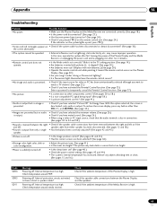
....) Enter a password to temporarily cancel the Parental Control function. (See page 37.) • No picture. • Is connection to 58.) • Is a non-compatible PC signal being input? (See page 58.) • Is picture adjustment correct? (See page 41.) • Audio is output but no image is cut off . • Is the sleep timer set correctly? Appendix 14 English Troubleshooting Problem • No power. Check the speaker cable connections between...
....) Enter a password to temporarily cancel the Parental Control function. (See page 37.) • No picture. • Is connection to 58.) • Is a non-compatible PC signal being input? (See page 58.) • Is picture adjustment correct? (See page 41.) • Audio is output but no image is cut off . • Is the sleep timer set correctly? Appendix 14 English Troubleshooting Problem • No power. Check the speaker cable connections between...


