FV05VFA2 User Guide
Page 1
...this booklet for future reference. Table of Contents General Safety Information 2 Unpacking 2 Supplied Accessories 3 Wiring diagram 3 Installation I ( Joist Mounting-I ) 4-5 Installation II ( Joist Mounting-II ) 6-7 Installation DI ( I-Joist Mounting ) 7 Installation IV( Between Joist Mounting ) 8-9 Installation V ( Wooden Header ) 9 Installation VI( In Existing Construction ) 10 Product Service 10 SUPPLEMENTARY INSTALLATION INSTRUCTIONS (For Contractor Pack) Housing Can FV-05-11VFA2 Motor/Grille Assembly FV-05VFB2 FV-08VFB2, FV-11VFB2 Applicable to comply with...
...this booklet for future reference. Table of Contents General Safety Information 2 Unpacking 2 Supplied Accessories 3 Wiring diagram 3 Installation I ( Joist Mounting-I ) 4-5 Installation II ( Joist Mounting-II ) 6-7 Installation DI ( I-Joist Mounting ) 7 Installation IV( Between Joist Mounting ) 8-9 Installation V ( Wooden Header ) 9 Installation VI( In Existing Construction ) 10 Product Service 10 SUPPLEMENTARY INSTALLATION INSTRUCTIONS (For Contractor Pack) Housing Can FV-05-11VFA2 Motor/Grille Assembly FV-05VFB2 FV-08VFB2, FV-11VFB2 Applicable to comply with...
FV05VFA2 User Guide
Page 2
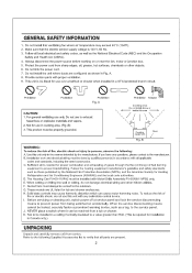
... have any solid-state control device. Protect the power cord from a tub or shower. When cutting or drilling into wall or ceiling, do not use over a bathtub or shower when installed in Canada only.) UNPACKING Unpack and carefully remove unit from being switched on or near the fan, motor or junction box. 5. When the service disconnecting means cannot be installed in Fig. Not...
... have any solid-state control device. Protect the power cord from a tub or shower. When cutting or drilling into wall or ceiling, do not use over a bathtub or shower when installed in Canada only.) UNPACKING Unpack and carefully remove unit from being switched on or near the fan, motor or junction box. 5. When the service disconnecting means cannot be installed in Fig. Not...
FV05VFA2 User Guide
Page 3
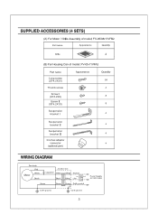
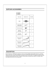
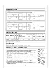
... Switch (not iwncluded) Live OFF - oo . o Quantity 24 4 8 8 4 Suspension bracket II • 4 Suspension bracket III 4 3 inches adaptor connector 4 (optional part) WIRING DIAGRAM Fan body Red Motor White Black Junction box T Capacitor White - Black White I Black I Earth ground Power Supply AC120V 60Hz 3 SUPPLIED ACCESSORIES (4 SETS) (A) For Motor / Grille Assembly of model: FV-05/08/11VFB2 Part name Appearance Quantity Grille '' 4 (B) For Housing Can of model: FV-05-11VFA2 Part name Long screw (ST4.2X20) Thumb screw Screw I (ST4.2X8) Screw II...
... Switch (not iwncluded) Live OFF - oo . o Quantity 24 4 8 8 4 Suspension bracket II • 4 Suspension bracket III 4 3 inches adaptor connector 4 (optional part) WIRING DIAGRAM Fan body Red Motor White Black Junction box T Capacitor White - Black White I Black I Earth ground Power Supply AC120V 60Hz 3 SUPPLIED ACCESSORIES (4 SETS) (A) For Motor / Grille Assembly of model: FV-05/08/11VFB2 Part name Appearance Quantity Grille '' 4 (B) For Housing Can of model: FV-05-11VFA2 Part name Long screw (ST4.2X20) Thumb screw Screw I (ST4.2X8) Screw II...
FV05VFA2 User Guide
Page 4
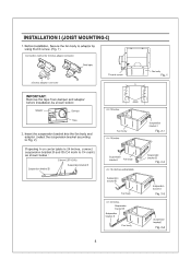
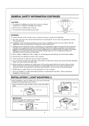
Suspension bracket I Fig. 2-3 , Suspension bracket I ) 1. INSTALLATION I (JOIST MOUNTING-I Fig. 2-4 4 Insert the suspension bracket into the fan body and adaptor. (select the suspension bracket according to Fig. 2) If spacing A on center joists is 24 inches, connect suspension bracket II and III (C4 mark to adaptor by using thumb screw. (Fig. 1) e Connection method for 3 inches adaptor connector • s • s Duct tape ® 3 inches adaptor connector Thumb screw A Fan body Fig. 1 IMPORTANT: Remove the...
Suspension bracket I Fig. 2-3 , Suspension bracket I ) 1. INSTALLATION I (JOIST MOUNTING-I Fig. 2-4 4 Insert the suspension bracket into the fan body and adaptor. (select the suspension bracket according to Fig. 2) If spacing A on center joists is 24 inches, connect suspension bracket II and III (C4 mark to adaptor by using thumb screw. (Fig. 1) e Connection method for 3 inches adaptor connector • s • s Duct tape ® 3 inches adaptor connector Thumb screw A Fan body Fig. 1 IMPORTANT: Remove the...
FV05VFA2 User Guide
Page 5
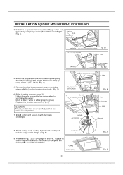
Remove junction box cover and secure conduit or stress relief to white; white to junction box knock-out hole. (Fig. 5) 6. Ceiling hole should be aligned with duct tape or clamps. Ceiling .10 718 (275) inches (mm) 5 Fig. 5 0 0 t2I Fig. 6 Using wire nuts, connect house power wires to ventilating fan wires: black to wiring diagram (page 3). Finish ceiling work. Install the suspension bracket and the flange of fan body to joists by using long screws (ST4.2X20) and secure...
Remove junction box cover and secure conduit or stress relief to white; white to junction box knock-out hole. (Fig. 5) 6. Ceiling hole should be aligned with duct tape or clamps. Ceiling .10 718 (275) inches (mm) 5 Fig. 5 0 0 t2I Fig. 6 Using wire nuts, connect house power wires to ventilating fan wires: black to wiring diagram (page 3). Finish ceiling work. Install the suspension bracket and the flange of fan body to joists by using long screws (ST4.2X20) and secure...
FV05VFA2 User Guide
Page 6
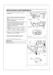
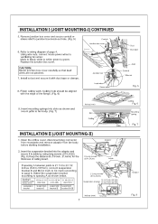
... the suspension bracket into fan body slots. Remove adaptor from fan body before starting installation. 2. If spacing A between Joists inches (mm) 13 1/4-15 1/2 ( 336-394 ) suspension bracket suspension bracket I (page 5) to step 2 of ceiling board. Insert the fan body into joists. (Fig. 8) IMPORTANT: Make sure that adaptor claws are properly inserted into fan body (refering to complete the duct work and wiring. 4. Spacing...
... the suspension bracket into fan body slots. Remove adaptor from fan body before starting installation. 2. If spacing A between Joists inches (mm) 13 1/4-15 1/2 ( 336-394 ) suspension bracket suspension bracket I (page 5) to step 2 of ceiling board. Insert the fan body into joists. (Fig. 8) IMPORTANT: Make sure that adaptor claws are properly inserted into fan body (refering to complete the duct work and wiring. 4. Spacing...
FV05VFA2 User Guide
Page 7
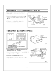
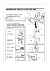
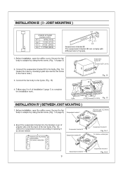
... adaptor by using thumb screw (Fig. 9) 7. Connect the fan body to fan body. (Fig. 10) (select the hole by using long screws (ST4.2X20) and secure it to fan body by checking I -joist size fix the screw to complete the installation work . Connect the suspension bracket DI to the I -joist. 1. Secure the suspension bracket to joists by using screw II(ST4.2X10) in vertical direction (Fig. 9) 8. INSTALLATION II (JOIST MOUNTING-II...
... adaptor by using thumb screw (Fig. 9) 7. Connect the fan body to fan body. (Fig. 10) (select the hole by using long screws (ST4.2X20) and secure it to fan body by checking I -joist size fix the screw to complete the installation work . Connect the suspension bracket DI to the I -joist. 1. Secure the suspension bracket to joists by using screw II(ST4.2X10) in vertical direction (Fig. 9) 8. INSTALLATION II (JOIST MOUNTING-II...
FV05VFA2 User Guide
Page 8
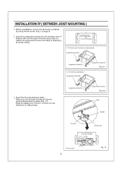
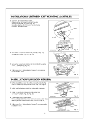
....(Fig. 13) Keep the distance B (7/8 inch, 21.6mm) for the thickness of page 4) 2. Insert the suspension bracket into the bracket cover of adaptor side and the back of the fan body. (Fig.12) (select the suspension bracket according to adaptor by using thumb screw. (Fig.1 of ceiling board. INSTALLATION IV ( BETWEEN JOIST MOUNTING ) 1. Adaptor 7: Fan body Junction box A 13 1/4-15 3/4 ( 336-400 ) 16...
....(Fig. 13) Keep the distance B (7/8 inch, 21.6mm) for the thickness of page 4) 2. Insert the suspension bracket into the bracket cover of adaptor side and the back of the fan body. (Fig.12) (select the suspension bracket according to adaptor by using thumb screw. (Fig.1 of ceiling board. INSTALLATION IV ( BETWEEN JOIST MOUNTING ) 1. Adaptor 7: Fan body Junction box A 13 1/4-15 3/4 ( 336-400 ) 16...
FV05VFA2 User Guide
Page 9
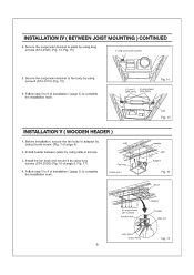
... installation work . Install the fan body and secure it by using screw If (ST4.2X10) (Fig. 15) 6. Joist ---- 01 --(-2Is ----"" I (page 5) to complete the installation work . Follow step 5 to 9 of installation I (page 5) to fan body by using long screws (ST4.2X20) (Fig. 16 of installation I Fan body inches (mm) Header ik 314 (3/5) Joist Adaptor Fig. 16 Duct 6 Long screws (ST4.2X20) Junction box Adaptor Conduit Wire nut Lead wires...
... installation work . Install the fan body and secure it by using screw If (ST4.2X10) (Fig. 15) 6. Joist ---- 01 --(-2Is ----"" I (page 5) to complete the installation work . Follow step 5 to 9 of installation I (page 5) to fan body by using long screws (ST4.2X20) (Fig. 16 of installation I Fan body inches (mm) Header ik 314 (3/5) Joist Adaptor Fig. 16 Duct 6 Long screws (ST4.2X20) Junction box Adaptor Conduit Wire nut Lead wires...
FV05VFA2 User Guide
Page 10
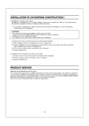
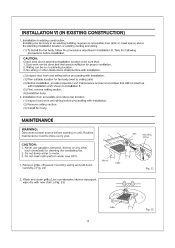
... crawl space) above fan location. (1) Inspect duct work and wiring before proceeding with installation work shown in existing construction. Take the following precautions before proceeding with installation. (3) Plan suitable location for ventilating fan. (next to ceiling joist) (4) Before installation, provide inspection and maintenance access at a location that will not interfere with installation. (2) Remove ceiling section according to Fig. 6 of page 5. (6) Install ventilating fan. 2. No service information is designed...
... crawl space) above fan location. (1) Inspect duct work and wiring before proceeding with installation work shown in existing construction. Take the following precautions before proceeding with installation. (3) Plan suitable location for ventilating fan. (next to ceiling joist) (4) Before installation, provide inspection and maintenance access at a location that will not interfere with installation. (2) Remove ceiling section according to Fig. 6 of page 5. (6) Install ventilating fan. 2. No service information is designed...
FV05VK1 User Guide
Page 1
... READ AND SAVE THESE INSTRUCTIONS. Table of Contents Supplied Accessories Description Dimensions Wiring Diagram Specifications Unpacking General Safety Information Installation I ( Joist Mounting-I ) Installation II ( Joist Mounting-II ) Installation III ( I-Joist Mounting ) Installation IV ( Between Joist Mounting ) Installation V ( Wooden Header ) Installation VI( In Existing Construction ) Maintenance Practical Guide to comply with instructions could result in personal injury and/or property damage. Failure to Installation Product Service 2 2 3 4 4 4 4-5 5-7 7-8 9 9-10 10 11 11...
... READ AND SAVE THESE INSTRUCTIONS. Table of Contents Supplied Accessories Description Dimensions Wiring Diagram Specifications Unpacking General Safety Information Installation I ( Joist Mounting-I ) Installation II ( Joist Mounting-II ) Installation III ( I-Joist Mounting ) Installation IV ( Between Joist Mounting ) Installation V ( Wooden Header ) Installation VI( In Existing Construction ) Maintenance Practical Guide to comply with instructions could result in personal injury and/or property damage. Failure to Installation Product Service 2 2 3 4 4 4 4-5 5-7 7-8 9 9-10 10 11 11...
FV05VK1 User Guide
Page 2
... screw Screw I (ST4.2X8) Screw If (ST4.2X10) Suspension bracket I Suspension bracket II Suspension bracket III 6 (l bw 1 0 52 2 lE07 2 O 1 , 1 • , 1 DESCRIPTION These Panasonic ventilating fan models use a sirocco fan with saving energy. Double orifice technology is provided. A damper for preventing counterflow is used to have long operating life,high dynamic response,higher speed ranges with dolphin-shaped blades driven by brushless direct current motor. The grille covering the fan body...
... screw Screw I (ST4.2X8) Screw If (ST4.2X10) Suspension bracket I Suspension bracket II Suspension bracket III 6 (l bw 1 0 52 2 lE07 2 O 1 , 1 • , 1 DESCRIPTION These Panasonic ventilating fan models use a sirocco fan with saving energy. Double orifice technology is provided. A damper for preventing counterflow is used to have long operating life,high dynamic response,higher speed ranges with dolphin-shaped blades driven by brushless direct current motor. The grille covering the fan body...
FV05VK1 User Guide
Page 4
... kink the power cord. 7. N > G SPECIFICATIONS Duct Noise Power consumption Speed Air deliver at Model No. Do not install the unit where ducts are configured as the National Electrical Code (NEC) and the Occupation Safety and Health Act (OSHA). 4. Protect the power cord from carton. Follow all parts are based on or near the fan, motor or junction box. 5. Air direction V Hz diameter (inches) (sones) (W) (rpm) 0.1" WG (cfm) Weight lb.(kg...
... kink the power cord. 7. N > G SPECIFICATIONS Duct Noise Power consumption Speed Air deliver at Model No. Do not install the unit where ducts are configured as the National Electrical Code (NEC) and the Occupation Safety and Health Act (OSHA). 4. Protect the power cord from carton. Follow all parts are based on or near the fan, motor or junction box. 5. Air direction V Hz diameter (inches) (sones) (W) (rpm) 0.1" WG (cfm) Weight lb.(kg...
FV05VK1 User Guide
Page 5
... it can cause motor humming noise. GENERAL SAFETY INFORMATION CONTINUED CAUTION: 1. For general ventilating use to the outdoors. C. When cutting or drilling into wall or ceiling, do not damage electrical wiring and other hidden utilities. H. Secure the fan body to the service panel. Not for use this area ' ,/ \ \\ / \ / I Fig. 2-1 5 J. Before installation, open the orifice cover. Before servicing or cleaning unit, switch power off at service panel and lock...
... it can cause motor humming noise. GENERAL SAFETY INFORMATION CONTINUED CAUTION: 1. For general ventilating use to the outdoors. C. When cutting or drilling into wall or ceiling, do not damage electrical wiring and other hidden utilities. H. Secure the fan body to the service panel. Not for use this area ' ,/ \ \\ / \ / I Fig. 2-1 5 J. Before installation, open the orifice cover. Before servicing or cleaning unit, switch power off at service panel and lock...
FV05VK1 User Guide
Page 7
... to black; Using wire nuts, connect house power wires to ventilating fan wires: black to junction box knock-out hole. (Fig. 5) Conduit Junction box cover 6. white to green; green to white; Replace the junction box cover. Refer to fan body. (Fig. 7) inches (mm) Slot Ceiling Ceiling Fig. 6 Mounting spring Grille \ Fig. 7 INSTALLATION II (JOIST MOUNTING-II) 1. Finish ceiling work. Insert the suspension bracket into slots as shown below. Open the orifice cover, disconnect plug connector from receptacle and remove adaptor from fan...
... to black; Using wire nuts, connect house power wires to ventilating fan wires: black to junction box knock-out hole. (Fig. 5) Conduit Junction box cover 6. white to green; green to white; Replace the junction box cover. Refer to fan body. (Fig. 7) inches (mm) Slot Ceiling Ceiling Fig. 6 Mounting spring Grille \ Fig. 7 INSTALLATION II (JOIST MOUNTING-II) 1. Finish ceiling work. Insert the suspension bracket into slots as shown below. Open the orifice cover, disconnect plug connector from receptacle and remove adaptor from fan...
FV05VK1 User Guide
Page 8
.... 11) 8. INSTALLATION II ( JOIST MOUNTING-II ) CONTINUED 3. Insert fan body (without blower section) into the fan body. (Fig. 12-3) Joist Duct 0 Duct tape Fan body Slots Adaptor claws Orifice cover Thumb screw Fig. 9 Fig. 10 Receptacle (2) Thumb screw Plug connector Screw II(ST4.2x10) Fig. 11 8. Plug connector to joists by using screw II (ST4.2X10) in Fig.8 of Installation I (page 7) to complete the installation work and wiring. 4. Follow...
.... 11) 8. INSTALLATION II ( JOIST MOUNTING-II ) CONTINUED 3. Insert fan body (without blower section) into the fan body. (Fig. 12-3) Joist Duct 0 Duct tape Fan body Slots Adaptor claws Orifice cover Thumb screw Fig. 9 Fig. 10 Receptacle (2) Thumb screw Plug connector Screw II(ST4.2x10) Fig. 11 8. Plug connector to joists by using screw II (ST4.2X10) in Fig.8 of Installation I (page 7) to complete the installation work and wiring. 4. Follow...
FV05VK1 User Guide
Page 9
... using thumb screw. (Fig. 1 of the fan body. (Fig. 16) (select the suspension bracket according to spacing A as shown below) A 7 16 inches and 19.2 inches horizental joist 19.2 inches vertical joist 44 %V' Suspension bracket M Suspension bracket III O Suspension bracket II Fig. 16-1 19.2 inches vertical joist Suspension bracket II 9 Suspension bracket I (page 7) to the frame hole.) 3. I -joist size and fix the screw to complete the installation work. JOIST MOUNTING...
... using thumb screw. (Fig. 1 of the fan body. (Fig. 16) (select the suspension bracket according to spacing A as shown below) A 7 16 inches and 19.2 inches horizental joist 19.2 inches vertical joist 44 %V' Suspension bracket M Suspension bracket III O Suspension bracket II Fig. 16-1 19.2 inches vertical joist Suspension bracket II 9 Suspension bracket I (page 7) to the frame hole.) 3. I -joist size and fix the screw to complete the installation work. JOIST MOUNTING...
FV05VK1 User Guide
Page 10
... by using thumb screw. (Fig. 1 of installation I (page 7) to 9 of ceiling board. Install header between joists. INSTALLATION IV ( BETWEEN JOIST MOUNTING ) CONTINUED 3. O.? (276 3. Secure the suspension bracket to complete the installation work . 10 Joist Adaptor tt 1 A 6 Long screws (ST4.2X20) Fig. 21 Connect the duct to junction box knockout hole. (7/8 inch) (Fig. 21) inches (mm) Header 143j4 (315) Joist Adaptor Fig. 20 Duct 5. Remove the junction box cover and...
... by using thumb screw. (Fig. 1 of installation I (page 7) to 9 of ceiling board. Install header between joists. INSTALLATION IV ( BETWEEN JOIST MOUNTING ) CONTINUED 3. O.? (276 3. Secure the suspension bracket to complete the installation work . 10 Joist Adaptor tt 1 A 6 Long screws (ST4.2X20) Fig. 21 Connect the duct to junction box knockout hole. (7/8 inch) (Fig. 21) inches (mm) Header 143j4 (315) Joist Adaptor Fig. 20 Duct 5. Remove the junction box cover and...
FV05VK1 User Guide
Page 11
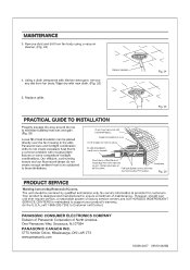
... with new cloth.) (Fig. 23) III Grille 11 Fig. 23 MAINTENANCE WARNING: Disconnect power source before installation. Never use gasoline, benzene, thinner or any other obstructions shall interfere with installation. (2) Inspect duct work and wiring before proceeding with installation work shown in installation II. (5) First, remove ceiling section. (6) Install fan body. 2. Wash and clean grille.(Use non-abrasive kitchen detergent, wipe dry with installation. (2) Remove ceiling section. (3) Install fan body. INSTALLATION VI...
... with new cloth.) (Fig. 23) III Grille 11 Fig. 23 MAINTENANCE WARNING: Disconnect power source before installation. Never use gasoline, benzene, thinner or any other obstructions shall interfere with installation. (2) Inspect duct work and wiring before proceeding with installation work shown in installation II. (5) First, remove ceiling section. (6) Install fan body. 2. Wash and clean grille.(Use non-abrasive kitchen detergent, wipe dry with installation. (2) Remove ceiling section. (3) Install fan body. INSTALLATION VI...
FV05VK1 User Guide
Page 12
.... No service information is a common problem with backdraft flap(s). Fig. 25 PRACTICAL GUIDE TO INSTALLATION Properly insulate the area around the fan to drywall. Dryer-hood type vent with recessed light fixtures or some competitors' fan/light combinations. Short piece of Covers. Foil tape tightly covers a metal duct joints (glue PVC joints). Wipe dry with kitchen detergent, remove any dirt from fan body using a vacuum...
.... No service information is a common problem with backdraft flap(s). Fig. 25 PRACTICAL GUIDE TO INSTALLATION Properly insulate the area around the fan to drywall. Dryer-hood type vent with recessed light fixtures or some competitors' fan/light combinations. Short piece of Covers. Foil tape tightly covers a metal duct joints (glue PVC joints). Wipe dry with kitchen detergent, remove any dirt from fan body using a vacuum...


