Panasonic FV08VFL2 Support and Manuals
Get Help and Manuals for this Panasonic item
View All Support Options Below
Free Panasonic FV08VFL2 manuals!
Problems with Panasonic FV08VFL2?
Ask a Question
Free Panasonic FV08VFL2 manuals!
Problems with Panasonic FV08VFL2?
Ask a Question
Popular Panasonic FV08VFL2 Manual Pages
Installation Instructions - Page 1

...Guide to comply with instructions could result in personal injury and/or property damage.
Please retain this booklet for future reference. INSTALLATION INSTRUCTIONS
Ventilating Fan
FV-05VFL2 FV-08VFL2 FV-11VFL2
0 FiI
N. -111
Panasonid
READ AND SAVE THESE INSTRUCTIONS. Please read these instructions carefully before attempting to install, operate or service the Panasonic Ventilating Fan...
Installation Instructions - Page 2

...sirocco fan developed to have an extended service life with dolphin-shaped blades driven by a capacitor motor. SUPPLIED ACCESSORIES
FV-05VFL2 FV-08VFL2 FV-11VFL2
Part name
Appearance
Quantity
Part ... -rn4im9.,.....1..IIP4' ,,
1
3 inches adaptor
connector
1
(optional part)
DESCRIPTION
These Panasonic ceiling mount ventilation fans use a sirocco fan with reduced energy consumption.
Installation Instructions - Page 3

Part name
8 Junction box 9 Lighting unit
10 Fluorescent lamp
11 Night lamp 12 Adaptor connector
13 Blade...bracket I II
13 (330)
NMI i0MIMENM %WI
43/8 (110)
4
51/2 (141)
10 1/4 (261) 16 1/8 (410)
J
No. Part name
1 Grille 2 Adaptor
3 Fan body
4 Damper 5 Suspension bracket
6 Bracket cover 7 Junction box cover
No. WIRING DIAGRAM
Current Fuse 3.15 A
Electronic Ballast
Fluorescent Lamp...
Installation Instructions - Page 4

SPECIFICATIONS
Model
Power consumption (W)
Air direction
V
Hz
Duct diameter (inches)
Noise (sones)
Fan body
Lighting unit
Fluorescent lamp Night lamp
FV-05VF L2
4
Installation Instructions - Page 5

... wiring must always be installed in accordance with any questions, contact to the outdoors. When the service disconnecting means cannot be done by the manufacturer. For general ventilating use to a value greater than R40. (This is needed for tub and shower enclosures. Use this unit with all applicable codes and standards, including fire...
Installation Instructions - Page 6

... body and adaptor. (Select the suspension bracket as shown below :
Adaptor
7-A070 Damper
RI MI I )
1. INSTALLATION I (JOIST MOUNTING-I Clill
Tape
2. Before installation, secure the fan body to C4 mark) as shown below)
A
O Fan body
Fig.1
Ca
Fan body
a
Suspension bracket I
Fig.2-1
a 0
Ili
1/i
i1
i1
Joists
Spacing A on center joists Insert Suspension bracket
12 inches
Refer...
Installation Instructions - Page 7

... duct (using 4 inches duct or 3 inches duct) and secure it to the fan body by using long screws (ST4.2X20). ( If spacing A between joists is 10 1/4-12 inches, install the flange of fan body
to wiring diagram below. white to green; Replace the junction box cover. ( Fig.5)
Wiring diagram
Current Fuse 3.15 A
Bectronic Ballast...
Installation Instructions - Page 8

... be aligned with 2 screw III (ST4.2X16) and 1 machine screw (M4X8). (Fig.6)
10. Disconnect plug connector from receptacle and remove adaptor from fan body before starting installation.
2.
Ceiling
Grille
Fig.7
INSTALLATION II (JOIST MOUNTING-II)
1. Select the suspension bracket according to joists by using long screws (ST4.2X20). (Fig.8) Ensure that distance B (7/8 inch...
Installation Instructions - Page 9

... installation I (page 8) to fan body by using long screws (ST4.2X20). (Fig.11)
7.
Remove adaptor from blower). (Fig.12-1)
Joist Conduit
Junction box cover
Duct tape or clamps
Circular duct
O
Fan body
Slots
Joist
Adaptor claws
2. Insert fan body (without blower section) into fan body (refering to receptacle. (Fig.10)
CD
)1 4 Screws
Joist
Screw driver
Fig...
Installation Instructions - Page 10

....13
CID
Suspension bracket III
Screw II (ST4.2X12)
1. Secure the lighting unit to fan body (refering to adaptor by checking I -joist size and fix the screw to the I -joist. Before installation, secure the fan body to Fig.6 of page 8).
2. INSTALLATION III ( I-JOIST MOUNTING )
4 kinds of I-joist inches (mm)
C1
9/16 (14.3)
C2 11...
Installation Instructions - Page 11

... 8).
2. Secure the suspension bracket to joists by using thumb screw (Fig.13 of ceiling board. Secure the lighting unit to fan body (refering to complete the installation work.
00
Joist
Fig.19
INSTALLATION V ( WOODEN HEADER )
1. Secure the suspension bracket to fan body by using long screws (ST4.2X20). (Fig.20, Fig.21)
Joist
0 7 (27t...
Installation Instructions - Page 12
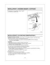
... (2) Remove ceiling section according to Fig.6 of page 8. (6) Install fan body. 2. Installing the fan body in an existing building requires an accessible area (attic or crawl space) above the planning installation location or existing ducting and wiring. (1) To install the fan body, follow the procedures described in installation (5) First, remove ceiling section according to be sure that will...
Installation Instructions - Page 13

... clean grille. (Use non-abrasive kitchen detergent, wipe dry with new cloth. (Fig.25)
5. Replace lamps and grille. MAINTENANCE I (CLEANING)
WARNING: Disconnect power source before working on unit. CAUTION: ...not soak resin parts in water over 60°C.
1. Using a cloth dampened with care. Disconnect power source before working on unit. 2. Remove dust and dirt from fan body. Please ...
Installation Instructions - Page 14

... fluorescent lamps (Panasonic FDS 18E2714,18 W or FDS18E35/4, 18 W or FDS18E42/4, 18 W ) or the 4 W night lamp, connect the connector II or connector III and replace the grille. (Fig.27)
Receptacle II Receptacle III
4 W Night lamp Fluorescent lamps
Fig.26
Fig.27
PRACTICAL GUIDE TO INSTALLATION
Proper insulate the area around the fan to drywall.
MAINTENANCE...
Panasonic FV08VFL2 Reviews
We have not received any reviews for Panasonic yet.