
Installation Instructions
Page 1
... of Contents Supplied Accessories Description Wiring Diagram Dimensions Specifications Unpacking General Safety Information Installation I ( Joist Mounting-I ) Installation II ( Joist Mounting-II ) Installation III ( I-Joist Mounting ) Installation IV( Between Joist Mounting ) Installation V ( Wooden Header ) Installation VI ( In Existing Construction ) Maintenance I ( Cleaning ) Maintenance II ( Replacement Of Lamp ) Practical Guide to install, operate or service the Panasonic Ventilating Fan. Please read these instructions carefully before attempting to Installation Product Service...
... of Contents Supplied Accessories Description Wiring Diagram Dimensions Specifications Unpacking General Safety Information Installation I ( Joist Mounting-I ) Installation II ( Joist Mounting-II ) Installation III ( I-Joist Mounting ) Installation IV( Between Joist Mounting ) Installation V ( Wooden Header ) Installation VI ( In Existing Construction ) Maintenance I ( Cleaning ) Maintenance II ( Replacement Of Lamp ) Practical Guide to install, operate or service the Panasonic Ventilating Fan. Please read these instructions carefully before attempting to Installation Product Service...

Installation Instructions
Page 2
... uses a high-capacity sirocco fan developed to have an extended service life with dolphin-shaped blades driven by a capacitor motor. The lighting unit is designed to reduce the noise level. A damper for safety. The grille can be quickly detached from the main unit. SUPPLIED ACCESSORIES FV-05VFL2 FV-08VFL2 FV-11VFL2 Part name Appearance Quantity Part name Appearance Quantity Grille Suspension bracket I 1 i , . ..----- 1 Suspension bracket...
... uses a high-capacity sirocco fan developed to have an extended service life with dolphin-shaped blades driven by a capacitor motor. The lighting unit is designed to reduce the noise level. A damper for safety. The grille can be quickly detached from the main unit. SUPPLIED ACCESSORIES FV-05VFL2 FV-08VFL2 FV-11VFL2 Part name Appearance Quantity Part name Appearance Quantity Grille Suspension bracket I 1 i , . ..----- 1 Suspension bracket...

Installation Instructions
Page 3
... 3 Fan body 4 Damper 5 Suspension bracket 6 Bracket cover 7 Junction box cover No. Part name 8 Junction box 9 Lighting unit 10 Fluorescent lamp 11 Night lamp 12 Adaptor connector 13 Blade (For 16 inches on center joists,only use suspension bracket II & 3 White Black Black White White Black B ack Black Green Green Green Lighting unit Neutral Live Neutral Live Power Supply AC 120 V 60 Hz Earth ground Earth ground Night Lamp Junction box Black White Black...
... 3 Fan body 4 Damper 5 Suspension bracket 6 Bracket cover 7 Junction box cover No. Part name 8 Junction box 9 Lighting unit 10 Fluorescent lamp 11 Night lamp 12 Adaptor connector 13 Blade (For 16 inches on center joists,only use suspension bracket II & 3 White Black Black White White Black B ack Black Green Green Green Lighting unit Neutral Live Neutral Live Power Supply AC 120 V 60 Hz Earth ground Earth ground Night Lamp Junction box Black White Black...

Installation Instructions
Page 4
SPECIFICATIONS Model Power consumption (W) Air direction V Hz Duct diameter (inches) Noise (sones) Fan body Lighting unit Fluorescent lamp Night lamp FV-05VF L2 4
SPECIFICATIONS Model Power consumption (W) Air direction V Hz Duct diameter (inches) Noise (sones) Fan body Lighting unit Fluorescent lamp Night lamp FV-05VF L2 4

Installation Instructions
Page 5
... cutting or drilling into wall or ceiling, do not use in Canada only.) 5 H. Not for Heating Refrigeration and Air Conditioning Engineers (ASHRAE) and the local code authorities. B Floor WARNING: To reduce the risk of fuel burning equipment to the service panel. Installation work and electrical wiring must be done by the manufacturer. D. Before servicing or cleaning unit, switch power off at service panel and lock the...
... cutting or drilling into wall or ceiling, do not use in Canada only.) 5 H. Not for Heating Refrigeration and Air Conditioning Engineers (ASHRAE) and the local code authorities. B Floor WARNING: To reduce the risk of fuel burning equipment to the service panel. Installation work and electrical wiring must be done by the manufacturer. D. Before servicing or cleaning unit, switch power off at service panel and lock the...

Installation Instructions
Page 6
... adaptor by using thumb screw.(Fig.1) Connection method for 3 inches adaptor connector Thumb screw • e • e Duct tape ® 3 inches adaptor connector IMPORTANT: Remove the tape from damper and adaptor before installation. Insert the suspension bracket into the fan body and adaptor. (Select the suspension bracket as shown below) A O Fan body Fig.1 Ca Fan body a Suspension bracket I Fig.2-4 6 INSTALLATION I (JOIST MOUNTING-I Clill Tape 2. Before installation, secure the fan body to...
... adaptor by using thumb screw.(Fig.1) Connection method for 3 inches adaptor connector Thumb screw • e • e Duct tape ® 3 inches adaptor connector IMPORTANT: Remove the tape from damper and adaptor before installation. Insert the suspension bracket into the fan body and adaptor. (Select the suspension bracket as shown below) A O Fan body Fig.1 Ca Fan body a Suspension bracket I Fig.2-4 6 INSTALLATION I (JOIST MOUNTING-I Clill Tape 2. Before installation, secure the fan body to...

Installation Instructions
Page 7
... pinched. 7. Install the suspension bracket to joists by using screw II (ST4.2X12). (Fig.4) 5. Using wire nuts, connect house power wires to ventilating fan wires: black to the fan body by using 4 inches duct or 3 inches duct) and secure it to black; INSTALLATION I (JOIST MOUNTING-I) CONTINUED 3. Refer to white; Replace the junction box cover. ( Fig.5) Wiring diagram Current Fuse 3.15 A Bectronic Ballast uorescent mp Fart body Motor Red T Capacitor White White White Black [21 Black White White Black Black Black Green Green G Ben Lighting unit...
... pinched. 7. Install the suspension bracket to joists by using screw II (ST4.2X12). (Fig.4) 5. Using wire nuts, connect house power wires to ventilating fan wires: black to the fan body by using 4 inches duct or 3 inches duct) and secure it to black; INSTALLATION I (JOIST MOUNTING-I) CONTINUED 3. Refer to white; Replace the junction box cover. ( Fig.5) Wiring diagram Current Fuse 3.15 A Bectronic Ballast uorescent mp Fart body Motor Red T Capacitor White White White Black [21 Black White White Black Black Black Green Green G Ben Lighting unit...

Installation Instructions
Page 8
... plug connector from receptacle and remove adaptor from fan body before starting installation. 2. inches (mm) 8 7/8 (21.5) Fig.8 Finish ceiling work and wiring. Insert the suspension bracket into the receptacle If and receptacle III respectively, and secure the lighting unit to the fan unit with the edge of the flange. (Fig.6) 9. If spacing A between Joists inches (mm) suspension bracket 13 1/4-15 1/2 ( 336-394) suspension bracket I g g Lighting unit 2 Screw...
... plug connector from receptacle and remove adaptor from fan body before starting installation. 2. inches (mm) 8 7/8 (21.5) Fig.8 Finish ceiling work and wiring. Insert the suspension bracket into the receptacle If and receptacle III respectively, and secure the lighting unit to the fan unit with the edge of the flange. (Fig.6) 9. If spacing A between Joists inches (mm) suspension bracket 13 1/4-15 1/2 ( 336-394) suspension bracket I g g Lighting unit 2 Screw...

Installation Instructions
Page 9
.... 9 O Thumb screw Plug connector I Receptacle I (page 8) to receptacle. (Fig.10) 7. Secure the fan body to adaptor by using long screws (ST4.2X20) and secure it to joists by using long screws (ST4.2X20). (Fig.11) 7. INSTALLATION II (JOIST MOUNTING-II ) CONTINUED 4. Secure the suspension bracket to joists as in vertical direction. (Fig.11) 8. Remove adaptor from blower). (Fig.12-1) Joist Conduit Junction box cover Duct...
.... 9 O Thumb screw Plug connector I Receptacle I (page 8) to receptacle. (Fig.10) 7. Secure the fan body to adaptor by using long screws (ST4.2X20) and secure it to joists by using long screws (ST4.2X20). (Fig.11) 7. INSTALLATION II (JOIST MOUNTING-II ) CONTINUED 4. Secure the suspension bracket to joists as in vertical direction. (Fig.11) 8. Remove adaptor from blower). (Fig.12-1) Joist Conduit Junction box cover Duct...

Installation Instructions
Page 10
... 8). 2. Connect the suspension bracket III to fan body. (Fig.14) (Select the hole by checking I (page 7-page 8) to the frame hole.) 3. Follow step 5 to 11 of installation I -joist size and fix the screw to complete the installation work. 1-joist Fig.14 4 Long screws (ST4.2X20) Fig.15 INSTALLATION IV ( BETWEEN JOIST MOUNTING ) 1. Secure the lighting unit to fan body (refering to adaptor by using thumb screw (Fig...
... 8). 2. Connect the suspension bracket III to fan body. (Fig.14) (Select the hole by checking I (page 7-page 8) to the frame hole.) 3. Follow step 5 to 11 of installation I -joist size and fix the screw to complete the installation work. 1-joist Fig.14 4 Long screws (ST4.2X20) Fig.15 INSTALLATION IV ( BETWEEN JOIST MOUNTING ) 1. Secure the lighting unit to fan body (refering to adaptor by using thumb screw (Fig...

Installation Instructions
Page 11
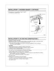
... page 8). 2. Adaptor Fan body Junction box A 13 1/4-15 3/4 (336-400) 16 1/2-183/4 (419-480) 3-5(76-126 54/5-7 4/5 ( 48-198) 4. Before installation, secure the fan body to fan body by using thumb screw (Fig.13 of ceiling board. Install header between joists. Secure the suspension bracket to adaptor by using long screws (ST4.2X20). (Fig.20, Fig.21) Joist 0 7 (27t Fan body inches (mm) Header...
... page 8). 2. Adaptor Fan body Junction box A 13 1/4-15 3/4 (336-400) 16 1/2-183/4 (419-480) 3-5(76-126 54/5-7 4/5 ( 48-198) 4. Before installation, secure the fan body to fan body by using thumb screw (Fig.13 of ceiling board. Install header between joists. Secure the suspension bracket to adaptor by using long screws (ST4.2X20). (Fig.20, Fig.21) Joist 0 7 (27t Fan body inches (mm) Header...
Installation Instructions
Page 12
... screws (ST4.2X20) Conduit Junction box 0 Adaptor Wire nut Lead wires Green wires Fig.21 INSTALLATION VI ( IN EXISTING CONSTRUCTION ) 1. Installation from accessible area above planning installation location to ceiling joist) (4) Before installation, provide inspection and maintenance access at a location that area is a a .! Circular duct Joists is sufficient for fan body. (next to be sure that: 1. Take the following precautions before proceeding with installation. (2) Remove ceiling...
... screws (ST4.2X20) Conduit Junction box 0 Adaptor Wire nut Lead wires Green wires Fig.21 INSTALLATION VI ( IN EXISTING CONSTRUCTION ) 1. Installation from accessible area above planning installation location to ceiling joist) (4) Before installation, provide inspection and maintenance access at a location that area is a a .! Circular duct Joists is sufficient for fan body. (next to be sure that: 1. Take the following precautions before proceeding with installation. (2) Remove ceiling...

Installation Instructions
Page 13
... clean grille. (Use non-abrasive kitchen detergent, wipe dry with care. Replace lamps and grille. Please handle with new cloth.) (Fig.23) Gloves Grille Slot Mounting spring Fig. 22 3. Remove grille. (Squeeze mounting spring and pull down carefully.) (Fig.22) 2. Disconnect power source before working on unit. 2. To remove lamp, grasp at base and move back and force to enter motor. 3. MAINTENANCE I (CLEANING...
... clean grille. (Use non-abrasive kitchen detergent, wipe dry with care. Replace lamps and grille. Please handle with new cloth.) (Fig.23) Gloves Grille Slot Mounting spring Fig. 22 3. Remove grille. (Squeeze mounting spring and pull down carefully.) (Fig.22) 2. Disconnect power source before working on unit. 2. To remove lamp, grasp at base and move back and force to enter motor. 3. MAINTENANCE I (CLEANING...

Installation Instructions
Page 14
... be placed directly over the fan housing in the attic. Short piece of lighting unit. (Fig.26) 3. Foil tape tightly covers a I metal duct joints (glue PVC joints). Dryer-hood type vent with recessed light fixtures or some competitors' fan/light combinations. In attic installation, caulk box to duct. 2-3 ft straight run before elbow. Our efficient, cool-running motors and our fluorescent bulbs do not...
... be placed directly over the fan housing in the attic. Short piece of lighting unit. (Fig.26) 3. Foil tape tightly covers a I metal duct joints (glue PVC joints). Dryer-hood type vent with recessed light fixtures or some competitors' fan/light combinations. In attic installation, caulk box to duct. 2-3 ft straight run before elbow. Our efficient, cool-running motors and our fluorescent bulbs do not...


