

WVCW974 User Guide
Page 1
ENGLISH Color CCTV Camera Operating Instructions WV-CW974 Model No. Before attempting to connect or operate this product, please read these instructions carefully and save this manual for future use. FRANÇAIS
ENGLISH Color CCTV Camera Operating Instructions WV-CW974 Model No. Before attempting to connect or operate this product, please read these instructions carefully and save this manual for future use. FRANÇAIS

WVCW974 User Guide
Page 4
... CLAIM OR ACTION FOR DAMAGES, BROUGHT BY ANY PERSON OR ORGANIZATION BEING PHOTOGENIC SUBJECT, DUE TO VIOLATION OF PRIVACY WITH THE RESULT OF THAT SURVEILLANCE-CAMERA's PICTURE, INCLUDING SAVED DATA, FOR SOME REASON, BECOMES PUBLIC OR IS USED FOR THE PURPOSE OTHER THAN SURVEILLANCE. -4- THIS PUBLICATION COULD INCLUDE TECHNICAL INACCURACIES OR...
... CLAIM OR ACTION FOR DAMAGES, BROUGHT BY ANY PERSON OR ORGANIZATION BEING PHOTOGENIC SUBJECT, DUE TO VIOLATION OF PRIVACY WITH THE RESULT OF THAT SURVEILLANCE-CAMERA's PICTURE, INCLUDING SAVED DATA, FOR SOME REASON, BECOMES PUBLIC OR IS USED FOR THE PURPOSE OTHER THAN SURVEILLANCE. -4- THIS PUBLICATION COULD INCLUDE TECHNICAL INACCURACIES OR...
WVCW974 User Guide
Page 5
...Front/rear sun shield mounting screws 2 pcs. (*one screw is pointing straight down (at night. ■ Digital Flip Normally, a camera needs to stop when it points straight down during surveillance causes output of an alarm signal. For example, you mask specific parts of the... the power on IP66*2 of the scene from 0° to track subjects passing directly under -40 °C {-40 °F}. Features This Color CCTV Camera is a video surveillance device that records images of nighttime intruders. ■ Internal Heating Fan Prevents snow and frost from building up to structure...
...Front/rear sun shield mounting screws 2 pcs. (*one screw is pointing straight down (at night. ■ Digital Flip Normally, a camera needs to stop when it points straight down during surveillance causes output of an alarm signal. For example, you mask specific parts of the... the power on IP66*2 of the scene from 0° to track subjects passing directly under -40 °C {-40 °F}. Features This Color CCTV Camera is a video surveillance device that records images of nighttime intruders. ■ Internal Heating Fan Prevents snow and frost from building up to structure...

WVCW974 User Guide
Page 6
... the detailed settings (page 41) of the camera falling down. Install the camera at night (approximately 10 lx). • Use the detection area mask (page 42) to 122 °F} and humidity is for an extended period of the color filter in a horizontal configuration, with care. To prevent ...electric shock, do not move vertically on the dome cover make it at a location that the people are no user-serviceable parts inside. Do not misuse the camera. Installing at the sun...
... the detailed settings (page 41) of the camera falling down. Install the camera at night (approximately 10 lx). • Use the detection area mask (page 42) to 122 °F} and humidity is for an extended period of the color filter in a horizontal configuration, with care. To prevent ...electric shock, do not move vertically on the dome cover make it at a location that the people are no user-serviceable parts inside. Do not misuse the camera. Installing at the sun...

WVCW974 User Guide
Page 7
...the case it is installed in of an image may become foggy. • Use in of an image may damage the camera or cause leaks. ■ CCD color filter burn-in the center of the picture, it will automatically reset its power. Burn-in a location where it happens ... will remain on the display. If such conditions persist even after you perform camera cleaning (page 40), use can cause deterioration of the CCD internal color filters, and discoloration of CRT. ■ Handle the camera carefully. Please ask the nearest service center about replacement and maintenance of an...
...the case it is installed in of an image may become foggy. • Use in of an image may damage the camera or cause leaks. ■ CCD color filter burn-in the center of the picture, it will automatically reset its power. Burn-in a location where it happens ... will remain on the display. If such conditions persist even after you perform camera cleaning (page 40), use can cause deterioration of the CCD internal color filters, and discoloration of CRT. ■ Handle the camera carefully. Please ask the nearest service center about replacement and maintenance of an...

WVCW974 User Guide
Page 8
... installation work in accordance with a soft cloth. ■ Downloading (saving) or uploading (recovering) camera setting information Camera setting information that each screw is a limit to 122 °F}) CCTV System Catalogue" or consult your retailer, and select a wall, ceiling or other special environments •... quality. Doing so can be used for more information, see the "Panasonic ■ Never install or use of the uploading process. ■ Self-diagnosing Function ■ Install the camera in areas where corrosive gas is unavoidable, be sure to take adequate...
... installation work in accordance with a soft cloth. ■ Downloading (saving) or uploading (recovering) camera setting information Camera setting information that each screw is a limit to 122 °F}) CCTV System Catalogue" or consult your retailer, and select a wall, ceiling or other special environments •... quality. Doing so can be used for more information, see the "Panasonic ■ Never install or use of the uploading process. ■ Self-diagnosing Function ■ Install the camera in areas where corrosive gas is unavoidable, be sure to take adequate...

WVCW974 User Guide
Page 9
...be earth grounded.) Important: • Before setting up the devices. -9- If the dome becomes foggy, remove it before hooking up the camera for a configuration where the camera's RS485 data port is used in one configuration. Be sure to disconnect the main power. ■ Beware of dust and automobile exhaust ...blows rain onto the dome cover while it is raining. (2) In the snow When it snows, snow may cause dirt to build up the camera. If the camera is installed when humidity is very high, moisture may not melt if the temperature falls below 10 °C {50 °F}. However, snow...
...be earth grounded.) Important: • Before setting up the devices. -9- If the dome becomes foggy, remove it before hooking up the camera for a configuration where the camera's RS485 data port is used in one configuration. Be sure to disconnect the main power. ■ Beware of dust and automobile exhaust ...blows rain onto the dome cover while it is raining. (2) In the snow When it snows, snow may cause dirt to build up the camera. If the camera is installed when humidity is very high, moisture may not melt if the temperature falls below 10 °C {50 °F}. However, snow...

WVCW974 User Guide
Page 10
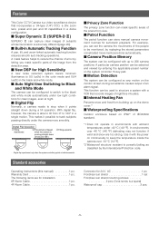
...■ Auto Night time Switching to Black and White Mode 5 ■ Digital Flip 5 ■ Privacy Zone Function 5 ■ Patrol Function 5 ■ Camera Position Memory 5 ■ Motion Detection 5 ■ Internal Heating Fan 5 ■ Waterproofing Specifications 5 Standard accessories 5 About the Auto-Tracking Function 6 Precautions ... 25 ■ Preset Position Settings 25 ■ Language Setting 27 ■ Advanced Menu Settings 27 Camera settings 28 ■ Using the Camera Setup Menu 28 Pan/Tilt settings 33 ■ Using the Pan/Tilt Setup Menu 33 Auto tracking ...
...■ Auto Night time Switching to Black and White Mode 5 ■ Digital Flip 5 ■ Privacy Zone Function 5 ■ Patrol Function 5 ■ Camera Position Memory 5 ■ Motion Detection 5 ■ Internal Heating Fan 5 ■ Waterproofing Specifications 5 Standard accessories 5 About the Auto-Tracking Function 6 Precautions ... 25 ■ Preset Position Settings 25 ■ Language Setting 27 ■ Advanced Menu Settings 27 Camera settings 28 ■ Using the Camera Setup Menu 28 Pan/Tilt settings 33 ■ Using the Pan/Tilt Setup Menu 33 Auto tracking ...

WVCW974 User Guide
Page 11
...• If cleaning the slip ring does not eliminate poor picture quality and noise, it replaced. -11- Ensuring Trouble-free Operation • This camera uses a "slip ring" for Heater Power Connector Attachment Pipe Upper Base Rear sun shield (provided) Front sun shield (provided) Sun shield (pre-...attached at factory) Dome cover (do not remove) Lens The lens cannot replaced. Construction Camera Safety Wire Alarm Input Connector Alarm Output Connector Video Output Connector Data Port Power Cord for transmission of noise. In order to have it...
...• If cleaning the slip ring does not eliminate poor picture quality and noise, it replaced. -11- Ensuring Trouble-free Operation • This camera uses a "slip ring" for Heater Power Connector Attachment Pipe Upper Base Rear sun shield (provided) Front sun shield (provided) Sun shield (pre-...attached at factory) Dome cover (do not remove) Lens The lens cannot replaced. Construction Camera Safety Wire Alarm Input Connector Alarm Output Connector Video Output Connector Data Port Power Cord for transmission of noise. In order to have it...

WVCW974 User Guide
Page 12
...in the ceiling or on a wall. ON ON 1234 4-line Communication 1234 2-line Communication -12- Dip switch settings In a configuration, the camera's RS485 data port is connected via a daisy chain over the DIP switches. Important: Do not adjust the DIP switches if you are all ...OFF. Switches 2 to specify the unit number and communication parameters. Put the protective sticker back over a long distance. Camera top view SW1 S TA R T RS485Setting SW2 ON 12 3 67 45 DIP SW1 8 Protective Sticker ON 4 3 2 1 DIP SW2 DIP Switch ■...
...in the ceiling or on a wall. ON ON 1234 4-line Communication 1234 2-line Communication -12- Dip switch settings In a configuration, the camera's RS485 data port is connected via a daisy chain over the DIP switches. Important: Do not adjust the DIP switches if you are all ...OFF. Switches 2 to specify the unit number and communication parameters. Put the protective sticker back over a long distance. Camera top view SW1 S TA R T RS485Setting SW2 ON 12 3 67 45 DIP SW1 8 Protective Sticker ON 4 3 2 1 DIP SW2 DIP Switch ■...

WVCW974 User Guide
Page 14
...: 8 bit, PARITY CHECK : NONE, STOP BIT : 1 bit ■ Procedure to setup dip switch 1 (1) Turn off the camera, use DIP Switch 1 to configure RS485 Communication Parameters as shown in Table-1), and then turn the camera back on again. -14- This applies the setting you configured in step (1). (3) Turn off the...using the Unit Number "1 ~ 96" setting, the unit number setting needs to set the unit number (as shown in Table-2. (2) Turn on the camera. You can then change the settings as desired. For details about configuring this setting, see step 2 on page 20. • Turning on power ...
...: 8 bit, PARITY CHECK : NONE, STOP BIT : 1 bit ■ Procedure to setup dip switch 1 (1) Turn off the camera, use DIP Switch 1 to configure RS485 Communication Parameters as shown in Table-1), and then turn the camera back on again. -14- This applies the setting you configured in step (1). (3) Turn off the...using the Unit Number "1 ~ 96" setting, the unit number setting needs to set the unit number (as shown in Table-2. (2) Turn on the camera. You can then change the settings as desired. For details about configuring this setting, see step 2 on page 20. • Turning on power ...

WVCW974 User Guide
Page 15
... with a locally procured bracket. wall nuts, anchor bolts, etc.) for weights. x4 -15- If the surface is not strong enough, the camera may fall down. The screws that are removed need to the product specifications for fixing on a ceiling with waterproof material. 2. x3 ● ... (2) Remove the attachment pipe from falling, use a mounting a bracket to which a safety wire can be used during reassembly. Camera installation ■ Mounting the Camera Ceiling mount The figure shows an example of the installation surface and structure. Turn the upper base and separate it. * Special ...
... with a locally procured bracket. wall nuts, anchor bolts, etc.) for weights. x4 -15- If the surface is not strong enough, the camera may fall down. The screws that are removed need to the product specifications for fixing on a ceiling with waterproof material. 2. x3 ● ... (2) Remove the attachment pipe from falling, use a mounting a bracket to which a safety wire can be used during reassembly. Camera installation ■ Mounting the Camera Ceiling mount The figure shows an example of the installation surface and structure. Turn the upper base and separate it. * Special ...

WVCW974 User Guide
Page 16
...Fix the attachment pipe to CONNECTIONS. Connect cables, referring to the bracket. (3) Thread cables through the bracket. If water gets inside the camera it could cause a shock or fire. Caution: Tighten the three (3) mounting screws for details. Make sure that water or moisture cannot get... the Bracket (1) Fix the bracket to become foggy. Warning: Carefully apply the sealing so that everything is tightened securely. 4. 3. Mounting the camera (1) Aim the "START" arrow at the bent portion of "2. Fall Prevention Wire Cables Upper Base (4) Fix the upper base to the attachment...
...Fix the attachment pipe to CONNECTIONS. Connect cables, referring to the bracket. (3) Thread cables through the bracket. If water gets inside the camera it could cause a shock or fire. Caution: Tighten the three (3) mounting screws for details. Make sure that water or moisture cannot get... the Bracket (1) Fix the bracket to become foggy. Warning: Carefully apply the sealing so that everything is tightened securely. 4. 3. Mounting the camera (1) Aim the "START" arrow at the bent portion of "2. Fall Prevention Wire Cables Upper Base (4) Fix the upper base to the attachment...

WVCW974 User Guide
Page 17
... sun shield with the "START" arrow (˚) on the sun shield and then turn them . Caution: The camera safety wire is attached to one side to prevent them to the camera. ■ Installing the brackets Refer to the installation guides provided with this arrow Wire Unhook 5. Hold the front...Sun shield ■ Attach the front and rear sun shields (provided) to be mounted. Put the waterproof caps (provided) onto the tops of the camera to hang from being lost. 4. Indented parts Align with the brackets. ■ Attach the brackets to attach them from it. Use the screws ...
... sun shield with the "START" arrow (˚) on the sun shield and then turn them . Caution: The camera safety wire is attached to one side to prevent them to the camera. ■ Installing the brackets Refer to the installation guides provided with this arrow Wire Unhook 5. Hold the front...Sun shield ■ Attach the front and rear sun shields (provided) to be mounted. Put the waterproof caps (provided) onto the tops of the camera to hang from being lost. 4. Indented parts Align with the brackets. ■ Attach the brackets to attach them from it. Use the screws ...

WVCW974 User Guide
Page 18
...Panasonic system equipment you are not exceeded. Drive capacity of at the fuse box before starting the installation work, or it on. Doing so can cause pan, tilt, zoom, or focus to go out of position. • 24 V AC Power Supply Connection Recommended wire gauge sizes for camera...1 24 V AC LIVE 2 24 V AC NEUTRAL 3 Ground 4 Not use shielded low-impedance cable with all local codes. • Turn off camera power within 30 seconds after turning it so could result in fire, electric shock, personal injury, and material damage. Connections Precautions • The following ...
...Panasonic system equipment you are not exceeded. Drive capacity of at the fuse box before starting the installation work, or it on. Doing so can cause pan, tilt, zoom, or focus to go out of position. • 24 V AC Power Supply Connection Recommended wire gauge sizes for camera...1 24 V AC LIVE 2 24 V AC NEUTRAL 3 Ground 4 Not use shielded low-impedance cable with all local codes. • Turn off camera power within 30 seconds after turning it so could result in fire, electric shock, personal injury, and material damage. Connections Precautions • The following ...

WVCW974 User Guide
Page 19
.... . 33 mmmm{{00.1.1"}"} UUpp A Insert WWiriere IInnsseertrtththeewwireireunutniltAil Apopsoitisointion aannddcclalammppthtehecocnotanctatsc. After clamping the contacts, push them into the proper holes in the accessory connector of this camera until ascertaining that the unit is a one-time procedure. Do not shrink the cable-entry seal until they snap in place. How to Assemble the...
.... . 33 mmmm{{00.1.1"}"} UUpp A Insert WWiriere IInnsseertrtththeewwireireunutniltAil Apopsoitisointion aannddcclalammppthtehecocnotanctatsc. After clamping the contacts, push them into the proper holes in the accessory connector of this camera until ascertaining that the unit is a one-time procedure. Do not shrink the cable-entry seal until they snap in place. How to Assemble the...

WVCW974 User Guide
Page 20
.... AUTO1 : Sends alarm data each time an alarm signal is NOT USE. This is 1. The delay time is the time is the time the camera should wait before sending a receive acknowledge (ACK). The factory default unit number is the factory default setting. 10. Move the cursor to XON/XOFF,...DIP Switch 1. Move the cursor to DATA BIT, and then tilt the joystick left or right to select a unit number (1 to control the camera (pan, tilt, etc.) via the camera's data port. 1. Tilting the joystick cycles through the baud rate (transmission speed) display in the sequence shown below . (unit: ms) ...
.... AUTO1 : Sends alarm data each time an alarm signal is NOT USE. This is 1. The delay time is the time is the time the camera should wait before sending a receive acknowledge (ACK). The factory default unit number is the factory default setting. 10. Move the cursor to XON/XOFF,...DIP Switch 1. Move the cursor to DATA BIT, and then tilt the joystick left or right to select a unit number (1 to control the camera (pan, tilt, etc.) via the camera's data port. 1. Tilting the joystick cycles through the baud rate (transmission speed) display in the sequence shown below . (unit: ms) ...
WVCW974 User Guide
Page 21
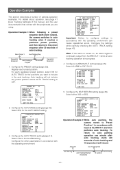
...and the user documentation that comes with the peripherals you want to include in accordance with the operating environment. ** AUTO TRACKING ** CAMERA HEIGHT 2.50M OBJECT SIZE SMALL SENSITIVITY MID TRACKING MODE MID ZOOM CONTROL CONTINUOUS AUTO RELEASE OFF LOST MODE ZOOM-OUT ALARM ON AREA... cause operational errors. Auto tracking will not include any preset position whose AUTO TRACK setting is in accordance with alarm output), the camera switches to auto tracking when it reaches a particular preset position, and then returns to Preset Position 1 in the auto tracking. ...
...and the user documentation that comes with the peripherals you want to include in accordance with the operating environment. ** AUTO TRACKING ** CAMERA HEIGHT 2.50M OBJECT SIZE SMALL SENSITIVITY MID TRACKING MODE MID ZOOM CONTROL CONTINUOUS AUTO RELEASE OFF LOST MODE ZOOM-OUT ALARM ON AREA... cause operational errors. Auto tracking will not include any preset position whose AUTO TRACK setting is in accordance with alarm output), the camera switches to auto tracking when it reaches a particular preset position, and then returns to Preset Position 1 in the auto tracking. ...

WVCW974 User Guide
Page 22
... tracking period from a home position at night. Configure the other parameters in accordance with the operating environment. **AUTO TRACKING** CAMERA HEIGHT 2.50M OBJECT SIZE SMALL SENSITIVITY MID TRACKING MODE MID ZOOM CONTROL CONTINUOUS AUTO RELEASE 50S LOST MODE ZOOM-OUT ALARM OFF... through 4 to auto tracking while tracking a target manually. 1. Configure each parameter in the center of the target. Operation Example 4: Camera follows a preset sequence without auto tracking during the day, and auto tracking from the start as preset position 1. While using manual operation...
... tracking period from a home position at night. Configure the other parameters in accordance with the operating environment. **AUTO TRACKING** CAMERA HEIGHT 2.50M OBJECT SIZE SMALL SENSITIVITY MID TRACKING MODE MID ZOOM CONTROL CONTINUOUS AUTO RELEASE 50S LOST MODE ZOOM-OUT ALARM OFF... through 4 to auto tracking while tracking a target manually. 1. Configure each parameter in the center of the target. Operation Example 4: Camera follows a preset sequence without auto tracking during the day, and auto tracking from the start as preset position 1. While using manual operation...

WVCW974 User Guide
Page 23
... AUTO TRACK setting (page 41). Configure the PRESET settings (page 33). Configure the settings while carefully checking the AUTO TRACK setting (page 41). 4. Use the Camera Event screen of the HD300 Series Setup Tool or the SX650 Series Setup Tool. (Refer to use the Setup Tool. -23- PRESET NO. 1* POSITION SET...
... AUTO TRACK setting (page 41). Configure the PRESET settings (page 33). Configure the settings while carefully checking the AUTO TRACK setting (page 41). 4. Use the Camera Event screen of the HD300 Series Setup Tool or the SX650 Series Setup Tool. (Refer to use the Setup Tool. -23- PRESET NO. 1* POSITION SET...


