SCHTB550 User Guide
Page 4
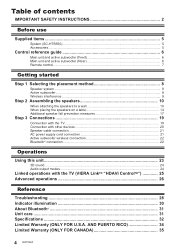
...6 Remote control...7 Getting started Step 1 Selecting the placement method 8 Speaker system ...9 Active subwoofer...9 Wireless interference ...9 Step 2 Assembling the speakers 10 When attaching the speakers to a wall 10 When placing the speakers on a table 14 Additional speaker fall prevention measures 17 Step 3 Connections 19 Connection with the TV......19 Connection with other devices 20 Speaker cable connection 21 AC power supply cord connection 21 Active subwoofer wireless connection 22 Bluetooth® connection...
...6 Remote control...7 Getting started Step 1 Selecting the placement method 8 Speaker system ...9 Active subwoofer...9 Wireless interference ...9 Step 2 Assembling the speakers 10 When attaching the speakers to a wall 10 When placing the speakers on a table 14 Additional speaker fall prevention measures 17 Step 3 Connections 19 Connection with the TV......19 Connection with other devices 20 Speaker cable connection 21 AC power supply cord connection 21 Active subwoofer wireless connection 22 Bluetooth® connection...
SCHTB550 User Guide
Page 5
... same. Supplied items System (SC-HTB550) ∏ 1 Main unit (SU-HTB550) ∏ 1 Active subwoofer (SB-HWA550) ∏ 2 Front speakers (SB-HTB550) Precautions Before use Getting started Operations Accessories Check the supplied accessories before using the system. ∏ 1 Remote control ∏ 2 AC ...power supply ∏ 2 Speaker cables (with this Owner's Manual are described mainly with the remote control, but you have made your purchase. ≥ The supplied...
... same. Supplied items System (SC-HTB550) ∏ 1 Main unit (SU-HTB550) ∏ 1 Active subwoofer (SB-HWA550) ∏ 2 Front speakers (SB-HTB550) Precautions Before use Getting started Operations Accessories Check the supplied accessories before using the system. ∏ 1 Remote control ∏ 2 AC ...power supply ∏ 2 Speaker cables (with this Owner's Manual are described mainly with the remote control, but you have made your purchase. ≥ The supplied...
SCHTB550 User Guide
Page 6
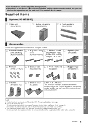
In standby mode, the unit is still consuming a small amount of power. 2 Adjust the volume of the speakers 3 Select the input source "TV"#"BD/DVD"#"AUX1" AUX2"(} 4 Remote control signal sensor (> 7) 5 Input selector indicators§1 A TV indicator Lights green when..., Multi-channel) is the current audio format 7 WIRELESS LINK indicator (> 22) Main unit and active subwoofer (Rear) 1 2 34 5 6 7 8 SPEAKERS / HAUT-PARLEURS AC IN R6 L 1 AC IN terminal (> 21) 2 Speaker terminals (> 21) 3 TV terminal (> 19) 4 AUX2 terminal (> 20) DIGITAL AUDIO IN TV (OPT1) AUX2 (OPT2) AV OUT TV (ARC) BD...
In standby mode, the unit is still consuming a small amount of power. 2 Adjust the volume of the speakers 3 Select the input source "TV"#"BD/DVD"#"AUX1" AUX2"(} 4 Remote control signal sensor (> 7) 5 Input selector indicators§1 A TV indicator Lights green when..., Multi-channel) is the current audio format 7 WIRELESS LINK indicator (> 22) Main unit and active subwoofer (Rear) 1 2 34 5 6 7 8 SPEAKERS / HAUT-PARLEURS AC IN R6 L 1 AC IN terminal (> 21) 2 Speaker terminals (> 21) 3 TV terminal (> 19) 4 AUX2 terminal (> 20) DIGITAL AUDIO IN TV (OPT1) AUX2 (OPT2) AV OUT TV (ARC) BD...
SCHTB550 User Guide
Page 8
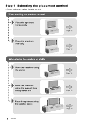
Step 1 Gettingstarted Selecting the placement method ≥Choose a placement method that suits you best. When attaching the speakers to a wall Place the speakers horizontally Page 10 Place the speakers vertically When placing the speakers on a table Place the speakers using the stands Page 12 Page 14 Place the speakers using the support legs and speaker feet Place the speakers using the speaker bases 8 RQT9660 Page 15 Page 16
Step 1 Gettingstarted Selecting the placement method ≥Choose a placement method that suits you best. When attaching the speakers to a wall Place the speakers horizontally Page 10 Place the speakers vertically When placing the speakers on a table Place the speakers using the stands Page 12 Page 14 Place the speakers using the support legs and speaker feet Place the speakers using the speaker bases 8 RQT9660 Page 15 Page 16
SCHTB550 User Guide
Page 9
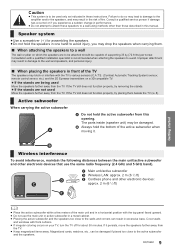
... beside the TV (> 8). If the TV still does not function properly, try removing the stands. ≥ If the stands are being used Move the speakers further away from the TV. ≥ Keep magnetized items away. B Always hold the bottom of the main unit and in excessive bass. C Main unit... be damaged. Cover walls and windows with thick curtains. ≥ If irregular coloring occurs on your TV, turn the TV off for assembling the speakers. ≥Do not hold the active subwoofer from the TV. Consult a qualified service person if damage has occurred or if you may block or...
... beside the TV (> 8). If the TV still does not function properly, try removing the stands. ≥ If the stands are being used Move the speakers further away from the TV. ≥ Keep magnetized items away. B Always hold the bottom of the main unit and in excessive bass. C Main unit... be damaged. Cover walls and windows with thick curtains. ≥ If irregular coloring occurs on your TV, turn the TV off for assembling the speakers. ≥Do not hold the active subwoofer from the TV. Consult a qualified service person if damage has occurred or if you may block or...
SCHTB550 User Guide
Page 10
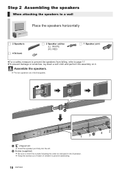
... the assembly on it. Step 2 Assembling the speakers When attaching the speakers to a wall Place the speakers horizontally ∏ 2 Speakers ∏ 4 Screws ∏ 2 Speaker cables (L): WHITE (R): RED ∏ 1 Speaker joint ≥For a safety measure to prevent the speakers from falling, refer to prevent swallowing. 10 RQT9660 Assemble the speakers. ≥ The two speakers are interchangeable. 1 3 4 2 A " " shaped slit...
... the assembly on it. Step 2 Assembling the speakers When attaching the speakers to a wall Place the speakers horizontally ∏ 2 Speakers ∏ 4 Screws ∏ 2 Speaker cables (L): WHITE (R): RED ∏ 1 Speaker joint ≥For a safety measure to prevent the speakers from falling, refer to prevent swallowing. 10 RQT9660 Assemble the speakers. ≥ The two speakers are interchangeable. 1 3 4 2 A " " shaped slit...
SCHTB550 User Guide
Page 11
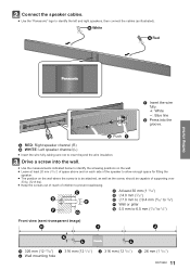
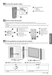
... (L) ≥ Insert the wire fully, taking care not to insert beyond the wire insulation. Connect the speaker cables. ≥ Use the "Panasonic" logo to identify the left and right speakers, then connect the cables (as the screw, should be capable of supporting over 33 kg (72.8 lbs). ≥ Keep the screws out of... to identify the screwing positions on the wall. ≥ Leave at least 20 mm (25/32q) of space above and on each side of the speaker to allow enough space for fitting the speaker. ≥ The position on the wall where the screw is to be attached, as well as illustrated).
... (L) ≥ Insert the wire fully, taking care not to insert beyond the wire insulation. Connect the speaker cables. ≥ Use the "Panasonic" logo to identify the left and right speakers, then connect the cables (as the screw, should be capable of supporting over 33 kg (72.8 lbs). ≥ Keep the screws out of... to identify the screwing positions on the wall. ≥ Leave at least 20 mm (25/32q) of space above and on each side of the speaker to allow enough space for fitting the speaker. ≥ The position on the wall where the screw is to be attached, as well as illustrated).
SCHTB550 User Guide
Page 12
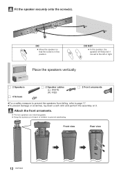
... a soft cloth and perform the assembly on it. DO ≥ Move the speaker so that the screw is in this position, the speaker will likely fall if moved to the left or right. Place the speakers vertically ∏ 2 Speakers ∏ 4 Screws ∏ 2 Speaker cables (L): WHITE (R): RED ∏ 2 Front ornaments ≥For a safety measure to prevent...
... a soft cloth and perform the assembly on it. DO ≥ Move the speaker so that the screw is in this position, the speaker will likely fall if moved to the left or right. Place the speakers vertically ∏ 2 Speakers ∏ 4 Screws ∏ 2 Speaker cables (L): WHITE (R): RED ∏ 2 Front ornaments ≥For a safety measure to prevent...
SCHTB550 User Guide
Page 13
...Leave at least 20 mm (25/32q) of space above and on each side of the speaker to allow enough space for fitting the speaker. ≥ The position in this position. ≥ In this position, the speaker will likely fall if moved to insert beyond the wire insulation. Getting started White ...J WHITE: Left speaker channel (L) DO Red K RED: Right speaker channel (R) DO NOT ≥ Move the speaker so that is in the wall where the screw is to be attached as well as the screw should be...
...Leave at least 20 mm (25/32q) of space above and on each side of the speaker to allow enough space for fitting the speaker. ≥ The position in this position. ≥ In this position, the speaker will likely fall if moved to insert beyond the wire insulation. Getting started White ...J WHITE: Left speaker channel (L) DO Red K RED: Right speaker channel (R) DO NOT ≥ Move the speaker so that is in the wall where the screw is to be attached as well as the screw should be...
SCHTB550 User Guide
Page 14
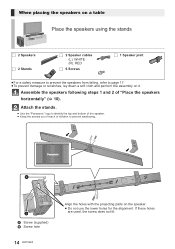
...Panasonic" logo to identify the top and bottom of the speaker. ≥ Keep the screws out of reach of "Place the speakers horizontally" (> 10). If these holes are used, the screw does not fit. When placing the speakers on a table Place the speakers using the stands ∏ 2 Speakers ∏ 2 Stands ∏ 2 Speaker... cables (L): WHITE (R): RED ∏ 6 Screws ∏ 1 Speaker joint ≥For a safety measure to prevent the speakers from falling, refer...
...Panasonic" logo to identify the top and bottom of the speaker. ≥ Keep the screws out of reach of "Place the speakers horizontally" (> 10). If these holes are used, the screw does not fit. When placing the speakers on a table Place the speakers using the stands ∏ 2 Speakers ∏ 2 Stands ∏ 2 Speaker... cables (L): WHITE (R): RED ∏ 6 Screws ∏ 1 Speaker joint ≥For a safety measure to prevent the speakers from falling, refer...
SCHTB550 User Guide
Page 15
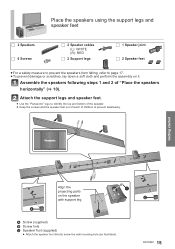
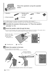
Attach the support legs and speaker feet. ≥ Use the "Panasonic" logo to identify the top and bottom of the speaker. ≥ Keep the screws and the speaker feet out of reach of "Place the speakers horizontally" (> 10). Assemble the speakers following steps 1 and 2 of children to page 17. ≥To prevent damage or scratches, lay down...
Attach the support legs and speaker feet. ≥ Use the "Panasonic" logo to identify the top and bottom of the speaker. ≥ Keep the screws and the speaker feet out of reach of "Place the speakers horizontally" (> 10). Assemble the speakers following steps 1 and 2 of children to page 17. ≥To prevent damage or scratches, lay down...
SCHTB550 User Guide
Page 16
... (4 21/64q) A Threading hole B Screw hole Attach the speaker to the base. ≥ The two speakers are interchangeable. ≥ Keep the screws out of reach of "Place the speakers vertically" (> 12). Place the speakers using the speaker bases ∏ 2 Speakers ∏ 2 Front ornaments ∏ 2 Speaker cables (L): WHITE (R): RED ∏ 6 Screws ∏ 2 Bases ≥For a safety...
... (4 21/64q) A Threading hole B Screw hole Attach the speaker to the base. ≥ The two speakers are interchangeable. ≥ Keep the screws out of reach of "Place the speakers vertically" (> 12). Place the speakers using the speaker bases ∏ 2 Speakers ∏ 2 Front ornaments ∏ 2 Speaker cables (L): WHITE (R): RED ∏ 6 Screws ∏ 2 Bases ≥For a safety...

SCHTB550 User Guide
Page 17
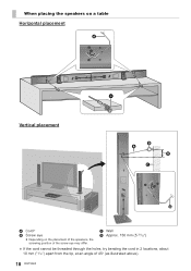
... Vertical placement A Cord§ B Screw eye C Wall D Wall-mounted speakers § If the cord cannot be threaded through the holes, try bending the cord in damage to the wall and...is recommended (> 11, 13). r: White s: Blue line Back of the base Getting started Push Press into the groove. ≥ Place the speaker that may result in 2 locations, about 1.5 mm (1/16q)). ≥ Keep the screws out of reach of 45o (as illustrated above). 17 RQT9660
... Vertical placement A Cord§ B Screw eye C Wall D Wall-mounted speakers § If the cord cannot be threaded through the holes, try bending the cord in damage to the wall and...is recommended (> 11, 13). r: White s: Blue line Back of the base Getting started Push Press into the groove. ≥ Place the speaker that may result in 2 locations, about 1.5 mm (1/16q)). ≥ Keep the screws out of reach of 45o (as illustrated above). 17 RQT9660
SCHTB550 User Guide
Page 18
C Wall D Approx. 150 mm (5 29/32q) § If the cord cannot be threaded through the holes, try bending the cord in 2 locations, about 10 mm (13/32q) apart from the tip, at an angle of the screw eye may differ. When placing the speakers on a table Horizontal placement Vertical placement A Cord§ B Screw eye ≥ Depending on the placement of the speakers, the screwing position of 45o (as illustrated above). 18 RQT9660
C Wall D Approx. 150 mm (5 29/32q) § If the cord cannot be threaded through the holes, try bending the cord in 2 locations, about 10 mm (13/32q) apart from the tip, at an angle of the screw eye may differ. When placing the speakers on a table Horizontal placement Vertical placement A Cord§ B Screw eye ≥ Depending on the placement of the speakers, the screwing position of 45o (as illustrated above). 18 RQT9660

SCHTB550 User Guide
Page 19
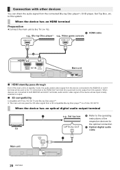
... cable): RP-CDHS15 (1.5 m/4.9 ft), RP-CDHS30 (3.0 m/9.8 ft), RP-CDHS50 (5.0 m/16.4 ft), etc. ≥ Non-HDMI-compliant cables cannot be enjoyed with a compatible Panasonic TV. ≥ Use the High Speed HDMI Cables. It refers to the operating instructions for the TV.) TV Getting started AV OUT TV (ARC... IN AV OUT TV (ARC) OPTICAL OUT HDMI IN TV DIGITAL AUDIO IN TV (OPT1) AV OUT TV (ARC) AC IN SPEAKERS / HAUT-PARLEURS R6 L A HDMI cable B Optical digital audio cable ≥ When you use the optical digital audio cable, insert the tip correctly into...
... cable): RP-CDHS15 (1.5 m/4.9 ft), RP-CDHS30 (3.0 m/9.8 ft), RP-CDHS50 (5.0 m/16.4 ft), etc. ≥ Non-HDMI-compliant cables cannot be enjoyed with a compatible Panasonic TV. ≥ Use the High Speed HDMI Cables. It refers to the operating instructions for the TV.) TV Getting started AV OUT TV (ARC... IN AV OUT TV (ARC) OPTICAL OUT HDMI IN TV DIGITAL AUDIO IN TV (OPT1) AV OUT TV (ARC) AC IN SPEAKERS / HAUT-PARLEURS R6 L A HDMI cable B Optical digital audio cable ≥ When you use the optical digital audio cable, insert the tip correctly into...
SCHTB550 User Guide
Page 20
... terminals, audio and/or video signal of the respective devices for the optimal connection OPTICAL OUT C Optical digital audio TV cable Main unit AC IN SPEAKERS / HAUT-PARLEURS DIGITAL AUDIO IN AUX2 (OPT2) DIGITAL AUDIO IN AUX2 (OPT2) 20 RQT9660 to the TV (> 19). When the device... Blu-ray Disc playerTM A HDMI cable e.g., Video game console HDMI OUT HDMI OUT BD/DVD (HDMI1) AV IN AUX1 (HDMI2) AC IN SPEAKERS / HAUT-PARLEURS DIGITAL AUDIO IN Main unit BD/DVD (HDMI1) AV IN AUX1 (HDMI2) ∫ HDMI standby pass-through Even if the main unit is...
... terminals, audio and/or video signal of the respective devices for the optimal connection OPTICAL OUT C Optical digital audio TV cable Main unit AC IN SPEAKERS / HAUT-PARLEURS DIGITAL AUDIO IN AUX2 (OPT2) DIGITAL AUDIO IN AUX2 (OPT2) 20 RQT9660 to the TV (> 19). When the device... Blu-ray Disc playerTM A HDMI cable e.g., Video game console HDMI OUT HDMI OUT BD/DVD (HDMI1) AV IN AUX1 (HDMI2) AC IN SPEAKERS / HAUT-PARLEURS DIGITAL AUDIO IN Main unit BD/DVD (HDMI1) AV IN AUX1 (HDMI2) ∫ HDMI standby pass-through Even if the main unit is...
SCHTB550 User Guide
Page 21
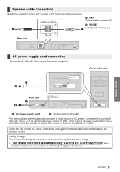
... household AC outlet. Install this unit so that the power cord can be using this unit: approx. 0.1 W, active subwoofer: approx. 0.1 W). Speaker cable connection Match the connector shape and connect to standby mode when no signal is input and no operation is turned off (this system for... time, unplug it from the socket outlet immediately if any problem occurs. Active subwoofer AC IN Main unit AC IN AC IN SPEAKERS / HAUT-PARLEURS DIGITAL AUDIO IN C AC power supply cord D To a household AC outlet ≥The main unit and active subwoofer consume a small...
... household AC outlet. Install this unit so that the power cord can be using this unit: approx. 0.1 W, active subwoofer: approx. 0.1 W). Speaker cable connection Match the connector shape and connect to standby mode when no signal is input and no operation is turned off (this system for... time, unplug it from the socket outlet immediately if any problem occurs. Active subwoofer AC IN Main unit AC IN AC IN SPEAKERS / HAUT-PARLEURS DIGITAL AUDIO IN C AC power supply cord D To a household AC outlet ≥The main unit and active subwoofer consume a small...
SCHTB550 User Guide
Page 23
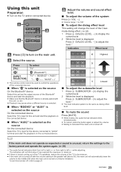
... 50), the main unit will not blink when it has reached the maximum or minimum. ≥ If there is sound coming out of the TV's speakers, reduce the volume of the TV to its minimum. ≥ If the main unit is turned off . Using this function off, refer to adjust the...
... 50), the main unit will not blink when it has reached the maximum or minimum. ≥ If there is sound coming out of the TV's speakers, reduce the volume of the TV to its minimum. ≥ If the main unit is turned off . Using this function off, refer to adjust the...
SCHTB550 User Guide
Page 24
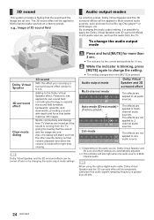
Adding to the Dolby Virtual Speaker effect, Panasonic has applied its own sound field controlling technology to Multichannel audio sources.... e.g., Image of 3D sound field Audio output modes As a factory preset, Dolby Virtual Speaker and the 3D surround effects will be temporarily canceled if the audio signal's sampling frequency is possible to apply ...the audio output mode settings. While the indicator is Multichannel audio. Audio output mode Dolby Virtual Speaker and 3D surround effect Multi-channel mode The effects are heard as a factory preset. When using the optical...
Adding to the Dolby Virtual Speaker effect, Panasonic has applied its own sound field controlling technology to Multichannel audio sources.... e.g., Image of 3D sound field Audio output modes As a factory preset, Dolby Virtual Speaker and the 3D surround effects will be temporarily canceled if the audio signal's sampling frequency is possible to apply ...the audio output mode settings. While the indicator is Multichannel audio. Audio output mode Dolby Virtual Speaker and 3D surround effect Multi-channel mode The effects are heard as a factory preset. When using the optical...

SCHTB550 User Guide
Page 25
.... "HDAVI Control 5" is a new name for details. ∫ Speaker control You can do with VIERA Link "HDAVI Control" To make sure that supports HDMI CEC cannot be output from this unit, and a Panasonic TV (VIERA) under "HDAVI Control". Refer to the operating instructions for...jWhen the TV input or the TV channel is changed , repeat this system will automatically change the speaker selection to on. See the operating instructions for connected equipment for Panasonic's HDAVI Control compatible equipment. When the connection or settings are performed, this procedure. §1 The ...
.... "HDAVI Control 5" is a new name for details. ∫ Speaker control You can do with VIERA Link "HDAVI Control" To make sure that supports HDMI CEC cannot be output from this unit, and a Panasonic TV (VIERA) under "HDAVI Control". Refer to the operating instructions for...jWhen the TV input or the TV channel is changed , repeat this system will automatically change the speaker selection to on. See the operating instructions for connected equipment for Panasonic's HDAVI Control compatible equipment. When the connection or settings are performed, this procedure. §1 The ...

