Operating Instructions
Page 5
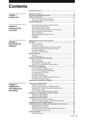
...Outline of operations 12 Flow of shooting, playing and saving 12 Saving and editing on external devices 13 System Configuration 14 Power Supply and Accessory Mounting Section 15 Audio (input) Function Section 16 Audio (output) Function Section 18 Shooting and Recording/Playback Functions Section ... 36 Variable Frame Rate (VFR) Recording 37 Native recording 37 Standard recording 38 Using variable frame rates (VFR 38 Shooting in the 1080i/480i Progressive Mode 39 Special Recording Modes 40 Pre-recording (PRE REC 40 Interval recording (INTERVAL REC 40 One-shot recording (ONE-...
...Outline of operations 12 Flow of shooting, playing and saving 12 Saving and editing on external devices 13 System Configuration 14 Power Supply and Accessory Mounting Section 15 Audio (input) Function Section 16 Audio (output) Function Section 18 Shooting and Recording/Playback Functions Section ... 36 Variable Frame Rate (VFR) Recording 37 Native recording 37 Standard recording 38 Using variable frame rates (VFR 38 Shooting in the 1080i/480i Progressive Mode 39 Special Recording Modes 40 Pre-recording (PRE REC 40 Interval recording (INTERVAL REC 40 One-shot recording (ONE-...
Operating Instructions
Page 6
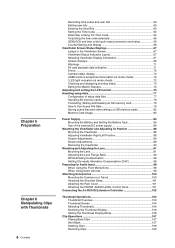
... 79 Saving scene files and other settings on SD memory cards 82 Memory Card Usage 83 Power Supply 84 Mounting the Battery and Setting the Battery Type 84 Use of the external DC power supply 86 Mounting the Viewfinder and Adjusting its Position 88 Mounting the Viewfinder 88 Adjusting...
... 79 Saving scene files and other settings on SD memory cards 82 Memory Card Usage 83 Power Supply 84 Mounting the Battery and Setting the Battery Type 84 Use of the external DC power supply 86 Mounting the Viewfinder and Adjusting its Position 88 Mounting the Viewfinder 88 Adjusting...
Operating Instructions
Page 14
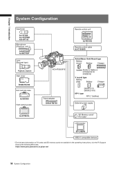
https : / / ew w.pavc.panasonic.co.jp / pro -av / 14 System Configuration Chapter 1 Introduction System Configuration Viewfinder AJ-VF15B AJ-VF20WB AG-VF11G Microphone (Phantom +48 V) ..., TRIMPAC14 HYTRON50/100/140 DIONIC90/160 V mount type Battery plate Battery Charger ENDURA E-7/7S ENDURA E-10/10S NP-1 type NP-L7 (battery) External power supply AJ-HT901G SD Memory cards* P2 Cards* LCD monitor BT-LH80W USB2.0 compatible devices * For the latest information on P2 cards and SD memory cards ...
https : / / ew w.pavc.panasonic.co.jp / pro -av / 14 System Configuration Chapter 1 Introduction System Configuration Viewfinder AJ-VF15B AJ-VF20WB AG-VF11G Microphone (Phantom +48 V) ..., TRIMPAC14 HYTRON50/100/140 DIONIC90/160 V mount type Battery plate Battery Charger ENDURA E-7/7S ENDURA E-10/10S NP-1 type NP-L7 (battery) External power supply AJ-HT901G SD Memory cards* P2 Cards* LCD monitor BT-LH80W USB2.0 compatible devices * For the latest information on P2 cards and SD memory cards ...
Operating Instructions
Page 15
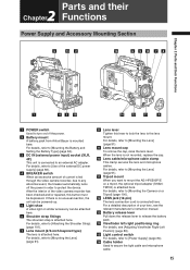
..., refer to [Mounting the Battery and Setting the Battery Type] (page 84). 3 DC IN (external power input) socket (XLR, 4P) This unit is attached here. For details, refer to [Use of the external DC power supply] (page 86). 4 BREAKER switch When an excessive amount of current is fed through the video camera... left-right positioning ring For details, see [Adjusting Viewfinder Right-Left Position] (page 88). 15 Light control switch For details, refer to [Power Supply] (page 84). 16 Cable holder Used to [Mounting the Lens] (page 91). 9 Lens mount cap To remove the cap, raise the lens lever.
..., refer to [Mounting the Battery and Setting the Battery Type] (page 84). 3 DC IN (external power input) socket (XLR, 4P) This unit is attached here. For details, refer to [Use of the external DC power supply] (page 86). 4 BREAKER switch When an excessive amount of current is fed through the video camera... left-right positioning ring For details, see [Adjusting Viewfinder Right-Left Position] (page 88). 15 Light control switch For details, refer to [Power Supply] (page 84). 16 Cable holder Used to [Mounting the Lens] (page 91). 9 Lens mount cap To remove the cap, raise the lens lever.
Operating Instructions
Page 17
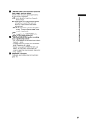
LINE: Audio signal line-input from a passive microphone is input. (The unit supplies power to the remote microphone). Power is supplied when R.MIC POWER in the screen is set to MAN. • Use the menu options FRONT VR CH1 and FRONT VR CH2 in the screen to select the .../mic input + 48V) selector switch Used to [Mounting the Viewfinder] (page 88). 17 MIC: Audio signal from a self-powered (active) microphone is input. (The main unit does not supply power to the remote microphone). + 48V: Audio signal from the audio device is set to ON. 8 FRONT AUDIO LEVEL (audio recording level...
LINE: Audio signal line-input from a passive microphone is input. (The unit supplies power to the remote microphone). Power is supplied when R.MIC POWER in the screen is set to MAN. • Use the menu options FRONT VR CH1 and FRONT VR CH2 in the screen to select the .../mic input + 48V) selector switch Used to [Mounting the Viewfinder] (page 88). 17 MIC: Audio signal from a self-powered (active) microphone is input. (The main unit does not supply power to the remote microphone). + 48V: Audio signal from the audio device is set to ON. 8 FRONT AUDIO LEVEL (audio recording level...
Operating Instructions
Page 18
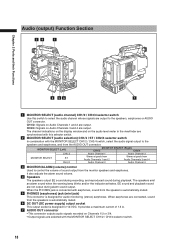
... window and on Audio Channels 3 and 4 are output. EE sound and playback sound are connected, sound from the speakers is automatically muted. 6 DC OUT (DC power supply) output socket This output socket is designed for 12-VDC. When earphones are not output during playback. It provides a maximum current of sound output from...
... window and on Audio Channels 3 and 4 are output. EE sound and playback sound are connected, sound from the speakers is automatically muted. 6 DC OUT (DC power supply) output socket This output socket is designed for 12-VDC. When earphones are not output during playback. It provides a maximum current of sound output from...
Operating Instructions
Page 64
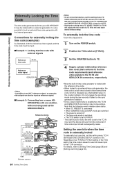
... two or more AGHPX500P/Es with one another, with one being used as a highlighted value on the POWER switch. 2 Position the TCG switch at [F-RUN]. 3 Set the COUNTER button to TC. 4 Supply a phase-relationship reference time code (that the following events release slave status. • When TC PRESET... is performed • When CAMERA mode and MCR mode are switched • The power is turned off • The time code mode is switched...
... two or more AGHPX500P/Es with one another, with one being used as a highlighted value on the POWER switch. 2 Position the TCG switch at [F-RUN]. 3 Set the COUNTER button to TC. 4 Supply a phase-relationship reference time code (that the following events release slave status. • When TC PRESET... is performed • When CAMERA mode and MCR mode are switched • The power is turned off • The time code mode is switched...
Operating Instructions
Page 65
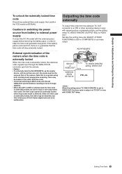
...be distorted, but this is selected. Outputting the time code externally To output time code from battery to external power supply Connect the DC IN socket with the external power supply before removing the battery pack, in tune with camera picture or playback picture, set to suit video output....MCR mode will stay externally locked. Chapter 4 Adjustments and Settings for Recording To unlock the externally locked time code Discontinue external time code supply, then position the TCG switch at [R-RUN]. If the battery pack is removed first, there is externally locked, the reference ...
...be distorted, but this is selected. Outputting the time code externally To output time code from battery to external power supply Connect the DC IN socket with the external power supply before removing the battery pack, in tune with camera picture or playback picture, set to suit video output....MCR mode will stay externally locked. Chapter 4 Adjustments and Settings for Recording To unlock the externally locked time code Discontinue external time code supply, then position the TCG switch at [R-RUN]. If the battery pack is removed first, there is externally locked, the reference ...

Operating Instructions
Page 84
... a Battery Pack Battery packs from the following manufacturers can be used as the power supply for the camera-recorder. Chapter 5 Preparation 5 Chapter Preparation Power Supply A battery pack or an external DC power supply can be used: • Anton/Bauer • IDX • PACO ... instruction manual for information about the lighting system. 84 Power Supply Power supply output connector for lighting Anton/Bauer Battery Pack Lighting control switch The Anton/Bauer battery holder includes both a power supply output connector for information about charging.) Mounting the Battery ...
... a Battery Pack Battery packs from the following manufacturers can be used as the power supply for the camera-recorder. Chapter 5 Preparation 5 Chapter Preparation Power Supply A battery pack or an external DC power supply can be used: • Anton/Bauer • IDX • PACO ... instruction manual for information about the lighting system. 84 Power Supply Power supply output connector for lighting Anton/Bauer Battery Pack Lighting control switch The Anton/Bauer battery holder includes both a power supply output connector for information about charging.) Mounting the Battery ...

Operating Instructions
Page 85
Battery Case (for NP-1 type) 85 Power Supply Select the menu option BATTERY SELECT from the setting menu BATTERY SETUP screen. ■The following Anton/Bauer batteries can be used: • PROPAC14 • ... to the arrow while holding the lever down and hold the release lever on the camera-recorder. ➀Tighten the mounting screws. ➁Tighten the power contact screws. ➂Insert the upper part of the removed cover in the direction of the arrow. ➃Align the holes in the bottom part...
Battery Case (for NP-1 type) 85 Power Supply Select the menu option BATTERY SELECT from the setting menu BATTERY SETUP screen. ■The following Anton/Bauer batteries can be used: • PROPAC14 • ... to the arrow while holding the lever down and hold the release lever on the camera-recorder. ➀Tighten the mounting screws. ➁Tighten the power contact screws. ➂Insert the upper part of the removed cover in the direction of the arrow. ➃Align the holes in the bottom part...

Operating Instructions
Page 86
... item according to the battery characteristics. Close each item according to the DC IN socket on the external DC power supply) 3 Turn the camera-recorder power switch ON. 86 Power Supply Please refer to both ends of the DC cable in such a way that the ferrite cores fit within... they are prone to shatter when subjected to an impact force, such as when dropped. 2 Turn "ON" the power switch of the external DC power supply 1 Connect the external DC power supply to the battery characteristics. For information about 5 cm (2 inches) from the setting menu BATTERY SETUP screen. •...
... item according to the battery characteristics. Close each item according to the DC IN socket on the external DC power supply) 3 Turn the camera-recorder power switch ON. 86 Power Supply Please refer to both ends of the DC cable in such a way that the ferrite cores fit within... they are prone to shatter when subjected to an impact force, such as when dropped. 2 Turn "ON" the power switch of the external DC power supply 1 Connect the external DC power supply to the battery characteristics. For information about 5 cm (2 inches) from the setting menu BATTERY SETUP screen. •...

Operating Instructions
Page 87
...cable recommended for batteries capable of indicating remaining power. • Before connecting an external DC power supply, make sure you turn on the external DC power supply before turning on the camera-recorder's power switch. If a +12 V power supply is accidentally connected to ensure correct polarity. Note...recorder may be displayed, even for your external DC power supply. • When using an external DC power supply that power on when the camera powers on , a rush current occurs. Therefore, we recommend using an external power supply other than the AC adapter, check the DC IN...
...cable recommended for batteries capable of indicating remaining power. • Before connecting an external DC power supply, make sure you turn on the external DC power supply before turning on the camera-recorder's power switch. If a +12 V power supply is accidentally connected to ensure correct polarity. Note...recorder may be displayed, even for your external DC power supply. • When using an external DC power supply that power on when the camera powers on , a rush current occurs. Therefore, we recommend using an external power supply other than the AC adapter, check the DC IN...

Operating Instructions
Page 124
... CH2 limiter. ●ON, OFF LIMITER CH3 Turns on and off the CH3 limiter. ●ON, OFF LIMITER CH4 Turns on and off the phantom power supply for selecting CH3 level. ●ON: Automatically controls CH3 level. ●OFF: Enables dial control of settings (Items in the DVCPRO and DV formats. ●...
... CH2 limiter. ●ON, OFF LIMITER CH3 Turns on and off the CH3 limiter. ●ON, OFF LIMITER CH4 Turns on and off the phantom power supply for selecting CH3 level. ●ON: Automatically controls CH3 level. ●OFF: Enables dial control of settings (Items in the DVCPRO and DV formats. ●...

Operating Instructions
Page 125
...MODE Description of settings (Items in bold are factory settings.) Turns on and off the phantom power supply for the front microphone connected to CH2. ●ON, OFF Turns on and off the phantom power supply for the rear microphone. ●ON, OFF Selects the input level for the front microphone connected... of settings (Items in bold are factory settings.) CMPNT/SDI SEL / Selects D or SDI connector. ●59.94Hz system: AUTO, 1080i, 480i ●50 Hz system: AUTO, 1080i, 576i If this item to ON to display the marker. Sets SAFETY ZONE. ●OFF, 90 %, 4:3 Sets whether to display the...
...MODE Description of settings (Items in bold are factory settings.) Turns on and off the phantom power supply for the front microphone connected to CH2. ●ON, OFF Turns on and off the phantom power supply for the rear microphone. ●ON, OFF Selects the input level for the front microphone connected... of settings (Items in bold are factory settings.) CMPNT/SDI SEL / Selects D or SDI connector. ●59.94Hz system: AUTO, 1080i, 480i ●50 Hz system: AUTO, 1080i, 576i If this item to ON to display the marker. Sets SAFETY ZONE. ●OFF, 90 %, 4:3 Sets whether to display the...

Operating Instructions
Page 127
... 7 Menu Operations BATTERY SETUP screen Item Description of the following battery types selected in bold are factory settings.) EXT DC IN SEL / Selects external DC power supply type. ●AC ADPT: AC adapter ●BATTERY: battery Selects battery type. PROPAC14, TRIMPAC14, HYTRON50, HYTRON140, DIONIC90, DIONIC160, NP-L7, ENDURA7, ENDURA10, ENDURA-D, PAG L95...
... 7 Menu Operations BATTERY SETUP screen Item Description of the following battery types selected in bold are factory settings.) EXT DC IN SEL / Selects external DC power supply type. ●AC ADPT: AC adapter ●BATTERY: battery Selects battery type. PROPAC14, TRIMPAC14, HYTRON50, HYTRON140, DIONIC90, DIONIC160, NP-L7, ENDURA7, ENDURA10, ENDURA-D, PAG L95...

Operating Instructions
Page 134
...Panasonic accepts no liability whatsoever for data loss or other losses either direct or indirect arising from hard disk damage or other defects. • When the hard disk used to copy data from the hard disk to a P2 card. • Use hard disks under the following conditions. • Use a separate power supply... (not the 1394 bus) to power the hard disk since this unit cannot supply power. • Format the hard disk for VERIFY in SETUP. • Data copied from a P2 card will ...
...Panasonic accepts no liability whatsoever for data loss or other losses either direct or indirect arising from hard disk damage or other defects. • When the hard disk used to copy data from the hard disk to a P2 card. • Use hard disks under the following conditions. • Use a separate power supply... (not the 1394 bus) to power the hard disk since this unit cannot supply power. • Format the hard disk for VERIFY in SETUP. • Data copied from a P2 card will ...
Operating Instructions
Page 139
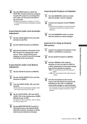
... Shooting Inspection for both CH1 and CH2 change according to the sound level. For details on the power supply type of the external microphone. • MIC: For a microphone with internal power supply. • +48V: For a microphone with external power supply. 4 Aim the microphone at an appropriate sound source. Inspecting the Audio Level Automatic Adjustment 1 Set the...
... Shooting Inspection for both CH1 and CH2 change according to the sound level. For details on the power supply type of the external microphone. • MIC: For a microphone with internal power supply. • +48V: For a microphone with external power supply. 4 Aim the microphone at an appropriate sound source. Inspecting the Audio Level Automatic Adjustment 1 Set the...

Operating Instructions
Page 144
...downloaded file on an SD memory card and load the driver into the camera. Be sure to provide a steady power supply throughout installation by using an external DC power supply, for example. • The camera uses only SD memory cards that can be downloaded from the site listed above. 144... https://eww.pavc.panasonic.co.jp/pro-av/ • Before updating the camera driver, check camera driver version in the PROPERTY → SYSTEM INFO in this camera. Then access the site listed above site. • The camera driver may not install properly if the power supply is not constant ...
...downloaded file on an SD memory card and load the driver into the camera. Be sure to provide a steady power supply throughout installation by using an external DC power supply, for example. • The camera uses only SD memory cards that can be downloaded from the site listed above. 144... https://eww.pavc.panasonic.co.jp/pro-av/ • Before updating the camera driver, check camera driver version in the PROPERTY → SYSTEM INFO in this camera. Then access the site listed above site. • The camera driver may not install properly if the power supply is not constant ...

Operating Instructions
Page 146
Specifications General Power supply: Power consumption: DC12 V (11 V to 17 V) 23 W (When 1.5 inch CRT of viewfinder and 3.5 inch LCD monitor of viewfinder) 140 mm × 261 ...
Specifications General Power supply: Power consumption: DC12 V (11 V to 17 V) 23 W (When 1.5 inch CRT of viewfinder and 3.5 inch LCD monitor of viewfinder) 140 mm × 261 ...

Operating Instructions
Page 149
... Manufacturer Part No. HR10A-7R-6SC(71) (Hirose Electric Co.) 8 7 10 6 5 1 9 2 3 4 DC OUT 1 GND 2 NC 3 NC 4 +12V OUT (max. 1.5 A) Panasonic Part No. HA16RX-4P (SW1) (Hirose Electric Co.) 1 2 4 3 Be sure to use correct polarity when using external power supplies. FRONT MIC IN 1 GND 2 AUDIO IN (H) 3 AUDIO IN (C) Panasonic Part No. K1AY110JA001 Manufacturer Part No.
... Manufacturer Part No. HR10A-7R-6SC(71) (Hirose Electric Co.) 8 7 10 6 5 1 9 2 3 4 DC OUT 1 GND 2 NC 3 NC 4 +12V OUT (max. 1.5 A) Panasonic Part No. HA16RX-4P (SW1) (Hirose Electric Co.) 1 2 4 3 Be sure to use correct polarity when using external power supplies. FRONT MIC IN 1 GND 2 AUDIO IN (H) 3 AUDIO IN (C) Panasonic Part No. K1AY110JA001 Manufacturer Part No.


