Installation Instructions
Page 1
... of Contents Supplied Accessories Description Wiring Diagram Dimensions Specifications Unpacking General Safety Information Installation I ( Joist Mounting-I ) Installation II ( Joist Mounting-II ) Installation III ( I-Joist Mounting ) Installation IV( Between Joist Mounting ) Installation V ( Wooden Header ) Installation VI ( In Existing Construction ) Maintenance I ( Cleaning ) Maintenance II ( Replacement Of Lamp ) Practical Guide to comply with instructions could result in personal injury and/or property damage. Failure to Installation Product Service 2 2 3 3 4 4 4-5 6-8 8-9 10 10-11...
... of Contents Supplied Accessories Description Wiring Diagram Dimensions Specifications Unpacking General Safety Information Installation I ( Joist Mounting-I ) Installation II ( Joist Mounting-II ) Installation III ( I-Joist Mounting ) Installation IV( Between Joist Mounting ) Installation V ( Wooden Header ) Installation VI ( In Existing Construction ) Maintenance I ( Cleaning ) Maintenance II ( Replacement Of Lamp ) Practical Guide to comply with instructions could result in personal injury and/or property damage. Failure to Installation Product Service 2 2 3 3 4 4 4-5 6-8 8-9 10 10-11...
Installation Instructions
Page 2
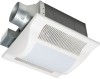
... preventing air counterflow is provided. The blower uses a high-capacity sirocco fan developed to have an extended service life with dolphin-shaped blades driven by a capacitor motor. The lighting unit is designed to reduce the noise level. The motor is an energy-saving, lighting device which uses two 18 W fluorescent lamps and produces almost the same illumination as a standard 100W incandescent lamp. 2 SUPPLIED ACCESSORIES...
... preventing air counterflow is provided. The blower uses a high-capacity sirocco fan developed to have an extended service life with dolphin-shaped blades driven by a capacitor motor. The lighting unit is designed to reduce the noise level. The motor is an energy-saving, lighting device which uses two 18 W fluorescent lamps and produces almost the same illumination as a standard 100W incandescent lamp. 2 SUPPLIED ACCESSORIES...
Installation Instructions
Page 3
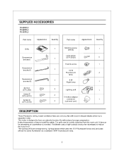
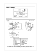
... Blade (For 16 inches on center joist, use suspension bracket I II 13 (330) NMI i0MIMENM %WI 43/8 (110) 4 51/2 (141) 10 1/4 (261) 16 1/8 (410) J No. Part name 1 Grille 2 Adaptor 3 Fan body 4 Damper 5 Suspension bracket 6 Bracket cover 7 Junction box cover No. WIRING DIAGRAM Current Fuse 3.15 A Electronic Ballast Fluorescent Lamp Fan body Motor Red T Capacitor White White - White Black Black White White Black B ack Black Green Green Green Lighting unit Neutral Live Neutral Live Power...
... Blade (For 16 inches on center joist, use suspension bracket I II 13 (330) NMI i0MIMENM %WI 43/8 (110) 4 51/2 (141) 10 1/4 (261) 16 1/8 (410) J No. Part name 1 Grille 2 Adaptor 3 Fan body 4 Damper 5 Suspension bracket 6 Bracket cover 7 Junction box cover No. WIRING DIAGRAM Current Fuse 3.15 A Electronic Ballast Fluorescent Lamp Fan body Motor Red T Capacitor White White - White Black Black White White Black B ack Black Green Green Green Lighting unit Neutral Live Neutral Live Power...

Installation Instructions
Page 4
SPECIFICATIONS Model Power consumption (W) Air direction V Hz Duct diameter (inches) Noise (sones) Fan body Lighting unit Fluorescent lamp Night lamp FV-05VF L2 4
SPECIFICATIONS Model Power consumption (W) Air direction V Hz Duct diameter (inches) Noise (sones) Fan body Lighting unit Fluorescent lamp Night lamp FV-05VF L2 4
Installation Instructions
Page 5
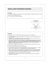
... motor humming noise. B Floor WARNING: To reduce the risk of fire or electric shock, do not damage electrical wiring and other hidden utilities. Sufficient air is required for use this area -I " / \ \ I \A \ // 45':// Cooking equipment Fig. H. When cutting or drilling into wall or ceiling, do not use in Canada only.) 5 E. G. If you have any solid-state control device. D. C. J. Before servicing or cleaning unit, switch power off at service...
... motor humming noise. B Floor WARNING: To reduce the risk of fire or electric shock, do not damage electrical wiring and other hidden utilities. Sufficient air is required for use this area -I " / \ \ I \A \ // 45':// Cooking equipment Fig. H. When cutting or drilling into wall or ceiling, do not use in Canada only.) 5 E. G. If you have any solid-state control device. D. C. J. Before servicing or cleaning unit, switch power off at service...
Installation Instructions
Page 6
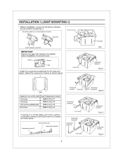
... to Fig. 2-2 19.2 inches vertical joists Refer to Fig. 2-3 24 inches Refer to Fig. 2-4 If spacing A on center joists is 24 inches, connect suspension bracket II and 114C4 mark to adaptor by using thumb screw.(Fig.1) Connection method for 3 inches adaptor connector Thumb screw • e • e Duct tape ® 3 inches adaptor connector IMPORTANT: Remove the tape from damper and adaptor before installation. INSTALLATION I (JOIST MOUNTING-I Clill Tape 2.
... to Fig. 2-2 19.2 inches vertical joists Refer to Fig. 2-3 24 inches Refer to Fig. 2-4 If spacing A on center joists is 24 inches, connect suspension bracket II and 114C4 mark to adaptor by using thumb screw.(Fig.1) Connection method for 3 inches adaptor connector Thumb screw • e • e Duct tape ® 3 inches adaptor connector IMPORTANT: Remove the tape from damper and adaptor before installation. INSTALLATION I (JOIST MOUNTING-I Clill Tape 2.
Installation Instructions
Page 7
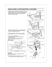
... Fig.3-1 to wiring diagram below. Replace the junction box cover. ( Fig.5) Wiring diagram Current Fuse 3.15 A Bectronic Ballast uorescent mp Fart body Motor Red T Capacitor White White White Black [21 Black White White Black Black Black Green Green G Ben Lighting unit Neutral Live Neutral Live Earth ground Power Supply AC 120 V 60 Hz Earth ground Night Lamp Junction box Black -- Using wire nuts, connect house power wires to ventilating fan wires: black to green; green to black; Remove junction box cover and secure...
... Fig.3-1 to wiring diagram below. Replace the junction box cover. ( Fig.5) Wiring diagram Current Fuse 3.15 A Bectronic Ballast uorescent mp Fart body Motor Red T Capacitor White White White Black [21 Black White White Black Black Black Green Green G Ben Lighting unit Neutral Live Neutral Live Earth ground Power Supply AC 120 V 60 Hz Earth ground Night Lamp Junction box Black -- Using wire nuts, connect house power wires to ventilating fan wires: black to green; green to black; Remove junction box cover and secure...
Installation Instructions
Page 8
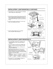
... lighting unit to complete the duct work . Insert the suspension bracket into the lighting unit.(Fig.6) 51 10 (Q) Ceiling Plug connectorII Plug connectorIII I (page 7) to the fan unit with the edge of the installation I g g Lighting unit 2 Screw Machine screw (ST4.2X16) (M4X8) Plug connector E Plug connector II 11. If spacing A between Joists inches (mm) suspension bracket 13 1/4-15 1/2 ( 336-394) suspension bracket I ) CONTINUED 8. Follow step 5 to joists by using long screws...
... lighting unit to complete the duct work . Insert the suspension bracket into the lighting unit.(Fig.6) 51 10 (Q) Ceiling Plug connectorII Plug connectorIII I (page 7) to the fan unit with the edge of the installation I g g Lighting unit 2 Screw Machine screw (ST4.2X16) (M4X8) Plug connector E Plug connector II 11. If spacing A between Joists inches (mm) suspension bracket 13 1/4-15 1/2 ( 336-394) suspension bracket I ) CONTINUED 8. Follow step 5 to joists by using long screws...
Installation Instructions
Page 9
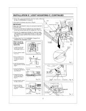
...-3) Blower Fig.12-2 a Fig.12-3 8. INSTALLATION II (JOIST MOUNTING-II ) CONTINUED 4. Insert the suspension bracket into joists. Secure the suspension bracket to joists by using long screws (ST4.2X20) and secure it to fan body by using thumb screw and plug connector to complete the installation work. Follow step 8 to step 2 of installation I Fig. 10 Screw II(ST4.2X12) g 2 Long screws (ST4.2X20) Joist Fig. 11...
...-3) Blower Fig.12-2 a Fig.12-3 8. INSTALLATION II (JOIST MOUNTING-II ) CONTINUED 4. Insert the suspension bracket into joists. Secure the suspension bracket to joists by using long screws (ST4.2X20) and secure it to fan body by using thumb screw and plug connector to complete the installation work. Follow step 8 to step 2 of installation I Fig. 10 Screw II(ST4.2X12) g 2 Long screws (ST4.2X20) Joist Fig. 11...
Installation Instructions
Page 10
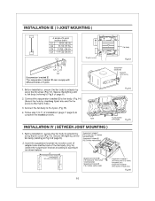
... adaptor by using thumb screw (Fig.13). Insert the suspension bracket into bracket cover of adaptor side and the back of installation I [19.2 inches vertical joist] Fig.16 10 Before installation, secure the fan body to complete the installation work. 1-joist Fig.14 4 Long screws (ST4.2X20) Fig.15 INSTALLATION IV ( BETWEEN JOIST MOUNTING ) 1. Connect the fan body to the I -joist size and fix the screw to adaptor...
... adaptor by using thumb screw (Fig.13). Insert the suspension bracket into bracket cover of adaptor side and the back of installation I [19.2 inches vertical joist] Fig.16 10 Before installation, secure the fan body to complete the installation work. 1-joist Fig.14 4 Long screws (ST4.2X20) Fig.15 INSTALLATION IV ( BETWEEN JOIST MOUNTING ) 1. Connect the fan body to the I -joist size and fix the screw to adaptor...
Installation Instructions
Page 11
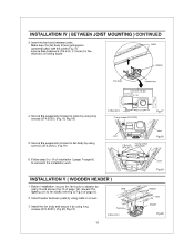
... B (7/8 inch, 21.6mm) for the thickness of page 8). 2. Secure the suspension bracket to Fig.6 of ceiling board. Adaptor Fan body Junction box A 13 1/4-15 3/4 (336-400) 16 1/2-183/4 (419-480) 3-5(76-126 54/5-7 4/5 ( 48-198) 4. Secure the suspension bracket to complete the installation work. 00 Joist Fig.19 INSTALLATION V ( WOODEN HEADER ) 1. Install the fan body and secure it by using thumb screw (Fig...
... B (7/8 inch, 21.6mm) for the thickness of page 8). 2. Secure the suspension bracket to Fig.6 of ceiling board. Adaptor Fan body Junction box A 13 1/4-15 3/4 (336-400) 16 1/2-183/4 (419-480) 3-5(76-126 54/5-7 4/5 ( 48-198) 4. Secure the suspension bracket to complete the installation work. 00 Joist Fig.19 INSTALLATION V ( WOODEN HEADER ) 1. Install the fan body and secure it by using thumb screw (Fig...
Installation Instructions
Page 12
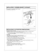
... planning installation location or existing ducting and wiring. (1) To install the fan body, follow the procedures described in existing construction. Duct work and wiring before installation. a 6 Long screws (ST4.2X20) Conduit Junction box 0 Adaptor Wire nut Lead wires Green wires Fig.21 INSTALLATION VI ( IN EXISTING CONSTRUCTION ) 1. Follow step 5 to 11 of installation I (page 7-page 8) to complete the installation work and wiring before proceeding with installation. (2) Inspect duct work can...
... planning installation location or existing ducting and wiring. (1) To install the fan body, follow the procedures described in existing construction. Duct work and wiring before installation. a 6 Long screws (ST4.2X20) Conduit Junction box 0 Adaptor Wire nut Lead wires Green wires Fig.21 INSTALLATION VI ( IN EXISTING CONSTRUCTION ) 1. Follow step 5 to 11 of installation I (page 7-page 8) to complete the installation work and wiring before proceeding with installation. (2) Inspect duct work can...
Installation Instructions
Page 13
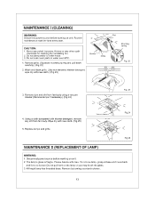
... motor. 3. Wash and clean grille. (Use non-abrasive kitchen detergent, wipe dry with new cloth. (Fig.25) 5. Wipe dry with new cloth.) (Fig.23) Gloves Grille Slot Mounting spring Fig. 22 3. Remove by turning counterclockwise. 13 Never use petrol, benzene, thinner or any dirt from fan body using a vacuum cleaner.(Remove lamps if necessary.) (Fig.24) Fig. 23 4. Disconnect power source before working...
... motor. 3. Wash and clean grille. (Use non-abrasive kitchen detergent, wipe dry with new cloth. (Fig.25) 5. Wipe dry with new cloth.) (Fig.23) Gloves Grille Slot Mounting spring Fig. 22 3. Remove by turning counterclockwise. 13 Never use petrol, benzene, thinner or any dirt from fan body using a vacuum cleaner.(Remove lamps if necessary.) (Fig.24) Fig. 23 4. Disconnect power source before working...
Installation Instructions
Page 14
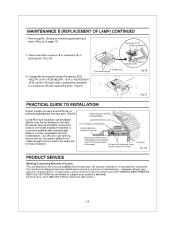
... placed directly over the fan housing in the attic. In attic installation, caulk box to ensure a minimum of factory service centers and AUTHORIZED INDEPENDENT SERVICE CENTERS is a common problem with backdraft flap(s). Clamps plustape at all flex joints. Fig. 28 PRODUCT SERVICE Warning Concerning Removal of page 13) Plug connectorIII Plug connectorII 2. MAINTENANCE II (REPLACEMENT OF LAMP) CONTINUED 1. Dryer-hood type vent with recessed light fixtures...
... placed directly over the fan housing in the attic. In attic installation, caulk box to ensure a minimum of factory service centers and AUTHORIZED INDEPENDENT SERVICE CENTERS is a common problem with backdraft flap(s). Clamps plustape at all flex joints. Fig. 28 PRODUCT SERVICE Warning Concerning Removal of page 13) Plug connectorIII Plug connectorII 2. MAINTENANCE II (REPLACEMENT OF LAMP) CONTINUED 1. Dryer-hood type vent with recessed light fixtures...


