
Installation Instructions
Page 1
... Joist Mounting ) Installation V ( Wooden Header ) Installation VI ( In Existing Construction ) Maintenance I ( Cleaning ) Maintenance II ( Replacement Of Lamp ) Practical Guide to install, operate or service the Panasonic Ventilating Fan. Please retain this booklet for future reference. Failure to comply with instructions could result in personal injury and/or property damage. INSTALLATION INSTRUCTIONS Ventilating...
... Joist Mounting ) Installation V ( Wooden Header ) Installation VI ( In Existing Construction ) Maintenance I ( Cleaning ) Maintenance II ( Replacement Of Lamp ) Practical Guide to install, operate or service the Panasonic Ventilating Fan. Please retain this booklet for future reference. Failure to comply with instructions could result in personal injury and/or property damage. INSTALLATION INSTRUCTIONS Ventilating...

Installation Instructions
Page 2
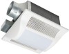
...thermal-cutoff for preventing air counterflow is designed to reduce the noise level. The motor is provided. The blower uses a high-capacity sirocco fan developed to have an extended service life with dolphin-shaped blades driven by a capacitor motor. The lighting unit is an energy-saving, lighting...; :3 6 Thumb screw el 1 18W Fluorescent 2 lamp 4 W • Night lamp 1 Lighting unit tr -rn4im9.,.....1..IIP4' ,, 1 3 inches adaptor connector 1 (optional part) DESCRIPTION These Panasonic ceiling mount ventilation fans use a sirocco fan with reduced energy consumption.
...thermal-cutoff for preventing air counterflow is designed to reduce the noise level. The motor is provided. The blower uses a high-capacity sirocco fan developed to have an extended service life with dolphin-shaped blades driven by a capacitor motor. The lighting unit is an energy-saving, lighting...; :3 6 Thumb screw el 1 18W Fluorescent 2 lamp 4 W • Night lamp 1 Lighting unit tr -rn4im9.,.....1..IIP4' ,, 1 3 inches adaptor connector 1 (optional part) DESCRIPTION These Panasonic ceiling mount ventilation fans use a sirocco fan with reduced energy consumption.

Installation Instructions
Page 3
Part name 1 Grille 2 Adaptor 3 Fan body 4 Damper 5 Suspension bracket 6 Bracket cover 7 Junction box cover No. Part name 8 Junction box 9 Lighting unit 10 Fluorescent lamp 11 Night lamp 12 Adaptor connector ... bracket I II 13 (330) NMI i0MIMENM %WI 43/8 (110) 4 51/2 (141) 10 1/4 (261) 16 1/8 (410) J No. WIRING DIAGRAM Current Fuse 3.15 A Electronic Ballast Fluorescent Lamp Fan body Motor Red T Capacitor White White -
Part name 1 Grille 2 Adaptor 3 Fan body 4 Damper 5 Suspension bracket 6 Bracket cover 7 Junction box cover No. Part name 8 Junction box 9 Lighting unit 10 Fluorescent lamp 11 Night lamp 12 Adaptor connector ... bracket I II 13 (330) NMI i0MIMENM %WI 43/8 (110) 4 51/2 (141) 10 1/4 (261) 16 1/8 (410) J No. WIRING DIAGRAM Current Fuse 3.15 A Electronic Ballast Fluorescent Lamp Fan body Motor Red T Capacitor White White -

Installation Instructions
Page 4
SPECIFICATIONS Model Power consumption (W) Air direction V Hz Duct diameter (inches) Noise (sones) Fan body Lighting unit Fluorescent lamp Night lamp FV-05VF L2 4
SPECIFICATIONS Model Power consumption (W) Air direction V Hz Duct diameter (inches) Noise (sones) Fan body Lighting unit Fluorescent lamp Night lamp FV-05VF L2 4

Installation Instructions
Page 5
... for tub and shower enclosures. D. F. B Floor WARNING: To reduce the risk of fire, electric shock or injury to the service panel. Use this area -I " / \ \ I . E. Ducted fans must be locked, securely fasten a prominent warning device, such as those published by qualified person(s) in a ceiling thermally insulated to exhaust hazardous or explosive materials...
... for tub and shower enclosures. D. F. B Floor WARNING: To reduce the risk of fire, electric shock or injury to the service panel. Use this area -I " / \ \ I . E. Ducted fans must be locked, securely fasten a prominent warning device, such as those published by qualified person(s) in a ceiling thermally insulated to exhaust hazardous or explosive materials...

Installation Instructions
Page 6
... a Suspension bracket I Clill Tape 2. Insert the suspension bracket into the fan body and adaptor. (Select the suspension bracket as shown below : Adaptor 7-A070 Damper RI MI I Fig.2-1 a 0 Ili 1/i i1 i1 Joists... installation. INSTALLATION I (JOIST MOUNTING-I Fig.2-4 6 As shown below : Suspension bracket III 2 Screw I (ST4.2X8) Suspension bracketII - -. • Suspension bracket I Fan body Suspension bracket III Fig.2-2 Suspension bracket III Fan body Suspension bracketlQ Suspension bracket II Op Fan body a 0 Suspension bracket I Fig.2-3 a Suspension bracket I ) 1.
... a Suspension bracket I Clill Tape 2. Insert the suspension bracket into the fan body and adaptor. (Select the suspension bracket as shown below : Adaptor 7-A070 Damper RI MI I Fig.2-1 a 0 Ili 1/i i1 i1 Joists... installation. INSTALLATION I (JOIST MOUNTING-I Fig.2-4 6 As shown below : Suspension bracket III 2 Screw I (ST4.2X8) Suspension bracketII - -. • Suspension bracket I Fan body Suspension bracket III Fig.2-2 Suspension bracket III Fan body Suspension bracketlQ Suspension bracket II Op Fan body a 0 Suspension bracket I Fig.2-3 a Suspension bracket I ) 1.

Installation Instructions
Page 7
... to joists by using long screws (ST4.2X20). ( If spacing A between joists is 10 1/4-12 inches, install the flange of Joist fan body according to Fig.3-2, others according to Fig.3-1 to white; Replace the junction box cover. ( Fig.5) Wiring diagram Current Fuse 3.15 ...and secure it to wiring diagram below. Install a circular duct (using screw II (ST4.2X12). (Fig.4) 5. white to install the product.) (CD Joist Fan body 4 Long screws (ST4.2X20) Fig.3-1 A=10 1/4-12 inches Joist 4. INSTALLATION I (JOIST MOUNTING-I) CONTINUED 3. Remove junction box cover and secure conduit...
... to joists by using long screws (ST4.2X20). ( If spacing A between joists is 10 1/4-12 inches, install the flange of Joist fan body according to Fig.3-2, others according to Fig.3-1 to white; Replace the junction box cover. ( Fig.5) Wiring diagram Current Fuse 3.15 ...and secure it to wiring diagram below. Install a circular duct (using screw II (ST4.2X12). (Fig.4) 5. white to install the product.) (CD Joist Fan body 4 Long screws (ST4.2X20) Fig.3-1 A=10 1/4-12 inches Joist 4. INSTALLATION I (JOIST MOUNTING-I) CONTINUED 3. Remove junction box cover and secure conduit...

Installation Instructions
Page 8
... to C4 mark) according to page 6. Insert mouting springs into the receptacle If and receptacle III respectively, and secure the lighting unit to fan body.(Fig.7) Fluorescent lamps 4 W Night lamp inches (mm) Receptacle II Receptacle E Fig.6 Slot Lighting unit Mounting spring .4-- Ceiling Grille ...Fig.7 INSTALLATION II (JOIST MOUNTING-II) 1. Select the suspension bracket according to spacing A as shown and mount grille to the fan unit with the edge of the flange. (Fig.6) 9. Follow step 5 to joists by using long screws (ST4.2X20). (Fig.8) Ensure that ...
... to C4 mark) according to page 6. Insert mouting springs into the receptacle If and receptacle III respectively, and secure the lighting unit to fan body.(Fig.7) Fluorescent lamps 4 W Night lamp inches (mm) Receptacle II Receptacle E Fig.6 Slot Lighting unit Mounting spring .4-- Ceiling Grille ...Fig.7 INSTALLATION II (JOIST MOUNTING-II) 1. Select the suspension bracket according to spacing A as shown and mount grille to the fan unit with the edge of the flange. (Fig.6) 9. Follow step 5 to joists by using long screws (ST4.2X20). (Fig.8) Ensure that ...

Installation Instructions
Page 9
... and plug connector to joists as in vertical direction. (Fig.11) 8. Insert fan body (without blower section) into body slots. 6. Secure the blower. (Fig.12-4) and plug connector to fan body by using thumb Fan body screw. (Fig.10) 6. Remove adaptor from blower). (Fig.12-1) Joist...to receptacle. (Fig.10) CD )1 4 Screws Joist Screw driver Fig.12-4 Fig. 9 O Thumb screw Plug connector I Receptacle I , page 6) 5. Insert the fan body into joists. (Fig.9) IMPORTANT: Make sure that adaptor claws are properly inserted into joists. Loosen 4 screws (but 0 do not remove them from...
... and plug connector to joists as in vertical direction. (Fig.11) 8. Insert fan body (without blower section) into body slots. 6. Secure the blower. (Fig.12-4) and plug connector to fan body by using thumb Fan body screw. (Fig.10) 6. Remove adaptor from blower). (Fig.12-1) Joist...to receptacle. (Fig.10) CD )1 4 Screws Joist Screw driver Fig.12-4 Fig. 9 O Thumb screw Plug connector I Receptacle I , page 6) 5. Insert the fan body into joists. (Fig.9) IMPORTANT: Make sure that adaptor claws are properly inserted into joists. Loosen 4 screws (but 0 do not remove them from...

Installation Instructions
Page 10
... bracket II [19.2 inches vertical joist] Suspension bracket II [16 inches and 19.2 inches horizental joist] Suspension bracket I -joist size and fix the screw to fan body. (Fig.14) (Select the hole by checking I [19.2 inches vertical joist] Fig.16 10 Secure the lighting unit to... (refering to adaptor by using thumb screw (Fig.13). Connect the suspension bracket III to the frame hole.) 3. Before installation, secure the fan body to Fig.6 of I-joist. INSTALLATION III ( I-JOIST MOUNTING ) 4 kinds of I-joist inches (mm) C1 9/16 (14.3) C2 11/16 (17.5) c C3 31/32 (24.6) ...
... bracket II [19.2 inches vertical joist] Suspension bracket II [16 inches and 19.2 inches horizental joist] Suspension bracket I -joist size and fix the screw to fan body. (Fig.14) (Select the hole by checking I [19.2 inches vertical joist] Fig.16 10 Secure the lighting unit to... (refering to adaptor by using thumb screw (Fig.13). Connect the suspension bracket III to the frame hole.) 3. Before installation, secure the fan body to Fig.6 of I-joist. INSTALLATION III ( I-JOIST MOUNTING ) 4 kinds of I-joist inches (mm) C1 9/16 (14.3) C2 11/16 (17.5) c C3 31/32 (24.6) ...

Installation Instructions
Page 11
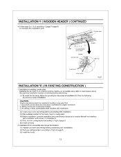
...2X12). (Fig.19) Joist 4 Long screws 2 Screw II (ST4.2X20) (ST4.2X12) Joist Fig.18 6. Install the fan body and secure it by using nails or screws. 3. Before installation, secure the fan body to adaptor by using long screws (ST4.2X20). (Fig.18, Fig.19) inches(mm) 7/8 (21.6) 2 Long ...Joist Fig.19 INSTALLATION V ( WOODEN HEADER ) 1. Follow step 5 to Fig.6 of ceiling board. Secure the lighting unit to fan body (refering to 11 of page 10). Make sure the fan body is level and square Joists (perpendicular) with the joists.(Fig.17) Ensure that distance B (7/8 inch, 21.6mm) for ...
...2X12). (Fig.19) Joist 4 Long screws 2 Screw II (ST4.2X20) (ST4.2X12) Joist Fig.18 6. Install the fan body and secure it by using nails or screws. 3. Before installation, secure the fan body to adaptor by using long screws (ST4.2X20). (Fig.18, Fig.19) inches(mm) 7/8 (21.6) 2 Long ...Joist Fig.19 INSTALLATION V ( WOODEN HEADER ) 1. Follow step 5 to Fig.6 of ceiling board. Secure the lighting unit to fan body (refering to 11 of page 10). Make sure the fan body is level and square Joists (perpendicular) with the joists.(Fig.17) Ensure that distance B (7/8 inch, 21.6mm) for ...
Installation Instructions
Page 12
... and that : 1. Installation from accessible area above the planning installation location or existing ducting and wiring. (1) To install the fan body, follow the procedures described in installation (5) First, remove ceiling section according to planning location. 3. No wiring or other ... (2) Inspect duct work and wiring before installation. INSTALLATION V ( WOODEN HEADER ) CONTINUED 4. Circular duct Joists is sufficient for fan body. (next to ceiling joist) (4) Before installation, provide inspection and maintenance access at a location that will not interfere with ...
... and that : 1. Installation from accessible area above the planning installation location or existing ducting and wiring. (1) To install the fan body, follow the procedures described in installation (5) First, remove ceiling section according to planning location. 3. No wiring or other ... (2) Inspect duct work and wiring before installation. INSTALLATION V ( WOODEN HEADER ) CONTINUED 4. Circular duct Joists is sufficient for fan body. (next to ceiling joist) (4) Before installation, provide inspection and maintenance access at a location that will not interfere with ...

Installation Instructions
Page 13
Remove dust and dirt from fan body. The lamp's glass is fragile. Do not damp water to loosen.Do not pull hard on the lamp or you may break the glass. 3. ..., wipe dry with care. CAUTION: 1. Replace lamps and grille. Routine maintenance must be done every year. Never use petrol, benzene, thinner or any dirt from fan body using a vacuum cleaner.(Remove lamps if necessary.) (Fig.24) Fig. 23 4. Using a cloth dampened with new cloth. (Fig.25) 5. Wipe dry with kitchen detergent...
Remove dust and dirt from fan body. The lamp's glass is fragile. Do not damp water to loosen.Do not pull hard on the lamp or you may break the glass. 3. ..., wipe dry with care. CAUTION: 1. Replace lamps and grille. Routine maintenance must be done every year. Never use petrol, benzene, thinner or any dirt from fan body using a vacuum cleaner.(Remove lamps if necessary.) (Fig.24) Fig. 23 4. Using a cloth dampened with new cloth. (Fig.25) 5. Wipe dry with kitchen detergent...

Installation Instructions
Page 14
...minimize building heat loss and gain. (Fig.28) Loose fill or batt insulation can be placed directly over the fan housing in the attic. Panasonic fans and fan/light combination units do not create enough ambient heat to ensure a minimum of flexible duct helps alignment and absorbs sound.... Change the fluorescent lamps (Panasonic FDS 18E2714,18 W or FDS18E35/4, 18 W or FDS18E42/4, 18 W ) or the 4 W night lamp, connect ...
...minimize building heat loss and gain. (Fig.28) Loose fill or batt insulation can be placed directly over the fan housing in the attic. Panasonic fans and fan/light combination units do not create enough ambient heat to ensure a minimum of flexible duct helps alignment and absorbs sound.... Change the fluorescent lamps (Panasonic FDS 18E2714,18 W or FDS18E35/4, 18 W or FDS18E42/4, 18 W ) or the 4 W night lamp, connect ...
