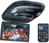
9" Overhead Monitor
Page 2
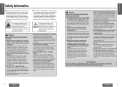
... install the product in a location where Using fuses that they do not wrap around your car audio system carefully before product. Using this product. while the car is only for q Run the cords so that exceed the prescribed capacity it with the battery's - replace the fuses. The air bag may result in this manual and the system properly. We shall not guarantee any problems...
... install the product in a location where Using fuses that they do not wrap around your car audio system carefully before product. Using this product. while the car is only for q Run the cords so that exceed the prescribed capacity it with the battery's - replace the fuses. The air bag may result in this manual and the system properly. We shall not guarantee any problems...

9" Overhead Monitor
Page 3
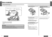
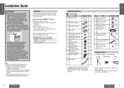
... dome light replaced by the base plate attached to heed this caution may break it will not become entangled or come Safety Installation Diagram 14 Open the Display Unit 15 into contact with your fingers between the base plate or car body. Wiring Diagram (Simple System)....... 30 Wiring Diagram (Recommended System 32 ≥ Gripping the bulb with another device, consult the operating instructions Installation Guide...
... dome light replaced by the base plate attached to heed this caution may break it will not become entangled or come Safety Installation Diagram 14 Open the Display Unit 15 into contact with your fingers between the base plate or car body. Wiring Diagram (Simple System)....... 30 Wiring Diagram (Recommended System 32 ≥ Gripping the bulb with another device, consult the operating instructions Installation Guide...
9" Overhead Monitor
Page 8
... display release button is reached. WARNING: Have a professional technician wire and install the product. E N G L I S H Safety Installation Diagram 1 ≥ This unit opens and closes at the maximum dimensions given below in the figure on the left and right, 30e each way. Note: ≥ Always use both hands until a comfortable viewing angle is locked. H Open the Display Unit [PUSH OPEN] 2 Display Unit Lateral Angle Adjustment...
... display release button is reached. WARNING: Have a professional technician wire and install the product. E N G L I S H Safety Installation Diagram 1 ≥ This unit opens and closes at the maximum dimensions given below in the figure on the left and right, 30e each way. Note: ≥ Always use both hands until a comfortable viewing angle is locked. H Open the Display Unit [PUSH OPEN] 2 Display Unit Lateral Angle Adjustment...
9" Overhead Monitor
Page 9
...; Identify and label the car wires. ≥ Connect the car wires to disconnect the battery's - Keep for installation. 16 CY-VHD9401U/L Supplied Hardware ª For Installation No. Needed for future reference in DC 12 V - Power connector 1 < Cord clamp 2 No. Item = Space washer (A) [t=1 mm {1/25q}] > Space washer (B) [t=2 mm {2/25q}] ? Space washer (C) [t=3 mm {3/25q}] @ Under cover E N G L I S H WARNING: 3 ≥ Use in case the product needs servicing. ≥ Installation Hardware...
...; Identify and label the car wires. ≥ Connect the car wires to disconnect the battery's - Keep for installation. 16 CY-VHD9401U/L Supplied Hardware ª For Installation No. Needed for future reference in DC 12 V - Power connector 1 < Cord clamp 2 No. Item = Space washer (A) [t=1 mm {1/25q}] > Space washer (B) [t=2 mm {2/25q}] ? Space washer (C) [t=3 mm {3/25q}] @ Under cover E N G L I S H WARNING: 3 ≥ Use in case the product needs servicing. ≥ Installation Hardware...

9" Overhead Monitor
Page 10
... to locate the car's battery lead. If the door switch is not wired correctly, the dome light will connect to this procedure. (The yellow battery lead provides continuous power to wire and install the unit. If the LCD monitor functions properly with the equipment. Note for one: Cut the connector wires one model to another so be absolutely sure to ask a dealer or service technician to maintain a clock, memory storage...
... to locate the car's battery lead. If the door switch is not wired correctly, the dome light will connect to this procedure. (The yellow battery lead provides continuous power to wire and install the unit. If the LCD monitor functions properly with the equipment. Note for one: Cut the connector wires one model to another so be absolutely sure to ask a dealer or service technician to maintain a clock, memory storage...
9" Overhead Monitor
Page 11
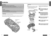
... panel 1 Ceiling reinforcement Remove the headliner from injuries. First remove the headliner. Failure to protect yourself from the vehicle for you purchased the product to install and wire it was and attach the main unit. Finally replace ...technician wire and install the product. Improper installation could result in failure of safety equipment resulting in an accident and/or injury. ≥ Wear goggles or protective eyewear to shield your reference. for installation. E N Installation G L I Work Flow S H Note: There are five main steps to wire and install the...
... panel 1 Ceiling reinforcement Remove the headliner from injuries. First remove the headliner. Failure to protect yourself from the vehicle for you purchased the product to install and wire it was and attach the main unit. Finally replace ...technician wire and install the product. Improper installation could result in failure of safety equipment resulting in an accident and/or injury. ≥ Wear goggles or protective eyewear to shield your reference. for installation. E N Installation G L I Work Flow S H Note: There are five main steps to wire and install the...
9" Overhead Monitor
Page 12
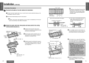
... your eyes from the car in which the unit is to be installed while taking care not to damage the interior or its fittings. 2 Now remove the dome light but leave its wiring in the ceiling reinforcement crosspieces to meet the mounting holes on the assembled plates. Do a preliminary check before starting work. 2 Attach the upper and...
... your eyes from the car in which the unit is to be installed while taking care not to damage the interior or its fittings. 2 Now remove the dome light but leave its wiring in the ceiling reinforcement crosspieces to meet the mounting holes on the assembled plates. Do a preliminary check before starting work. 2 Attach the upper and...
9" Overhead Monitor
Page 13
Consult a service technician as the installation position. Cut out Front side E N G L I 3 S H Wire the unit and replace the headliner. 11 1 Connect the wiring of the dome light and the unit, and bring the wiring as far as needed. ≥ Both positive and negative switched light circuits are two common types of dome light circuits used, positive or negative switched. CY-VHD9401U/L 25 If the door switch is not pinched...
Consult a service technician as the installation position. Cut out Front side E N G L I 3 S H Wire the unit and replace the headliner. 11 1 Connect the wiring of the dome light and the unit, and bring the wiring as far as needed. ≥ Both positive and negative switched light circuits are two common types of dome light circuits used, positive or negative switched. CY-VHD9401U/L 25 If the door switch is not pinched...

9" Overhead Monitor
Page 14
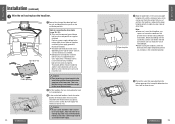
...26 CY-VHD9401U/L E N G L I 4 S H Get ready to attach the main unit. 13 1 Open the display unit and remove the 2 screws. A Space washer (D) [t=80 mm {33/16q}] Caution: ≥ Before installing the unit, be used, make any contact with the ceiling panel. Main unit : Flat washer [No. 10 (5 mm‡)] 9 Spring washer [No. 10 (5 ...the headliner and the main unit. Keep them in a place where they will be needed when you remove now will not be the same in the main unit. For gaps, adjust the under cover (@) to the underside of the front cover when removing it. ≥ The ...
...26 CY-VHD9401U/L E N G L I 4 S H Get ready to attach the main unit. 13 1 Open the display unit and remove the 2 screws. A Space washer (D) [t=80 mm {33/16q}] Caution: ≥ Before installing the unit, be used, make any contact with the ceiling panel. Main unit : Flat washer [No. 10 (5 mm‡)] 9 Spring washer [No. 10 (5 ...the headliner and the main unit. Keep them in a place where they will be needed when you remove now will not be the same in the main unit. For gaps, adjust the under cover (@) to the underside of the front cover when removing it. ≥ The ...
9" Overhead Monitor
Page 15
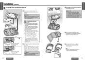
... are supported by this unit's door switch. E N Installation (continued) G L I 5 S H Connect the wires and attach the main unit. 15 1 Connect the wires (page 30 to 35) which were pulled out in the rear seat side a 1 (at 1 position) 2 Bind the wires using the cord clamps ( If the door switch is not wired correctly, the dome light will not come on , negative switched systems apply ground to wire and install the unit. Consult a service...
... are supported by this unit's door switch. E N Installation (continued) G L I 5 S H Connect the wires and attach the main unit. 15 1 Connect the wires (page 30 to 35) which were pulled out in the rear seat side a 1 (at 1 position) 2 Bind the wires using the cord clamps ( If the door switch is not wired correctly, the dome light will not come on , negative switched systems apply ground to wire and install the unit. Consult a service...
9" Overhead Monitor
Page 16
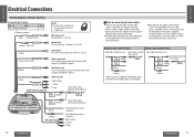
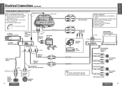
...-VHD9401U/L E N G L I S H Wiring Diagram (Simple System) 17 Accessory used for connecting the dome lights 18 ≥ There are supported by this unit's door Positive systems supply voltage to the negative door switched type.) CY-VHD9401U/L 31 Item ; VIDEO-CONT (Green/yellow stripe) Video control lead To the video control lead of the Panasonic DVD changer (CX-DH801U, option). (Black) REMOTE-OUT Remote-out cord To the remote input terminal of the car chassis...
...-VHD9401U/L E N G L I S H Wiring Diagram (Simple System) 17 Accessory used for connecting the dome lights 18 ≥ There are supported by this unit's door Positive systems supply voltage to the negative door switched type.) CY-VHD9401U/L 31 Item ; VIDEO-CONT (Green/yellow stripe) Video control lead To the video control lead of the Panasonic DVD changer (CX-DH801U, option). (Black) REMOTE-OUT Remote-out cord To the remote input terminal of the car chassis...
9" Overhead Monitor
Page 17
... DVD changer's (CX-DH801U, option) video control lead. ≥ For wiring, carefully read the operating instructions for the devices connected. Rear speaker + (option) - Remote control unit: ≥The remote control unit supplied with the CX-DH801U must be received by this unit (CY-VHD9401U/ CY-VHD9401L). (Do not connect the remote control signal receiver supplied with CX-DH801U when this connection has been performed.) Connections: ≥ Connect this unit's (CY-VHD9401U/ CY-VHD9401L) remote-out cord to the REMOTE-IN connector...
... DVD changer's (CX-DH801U, option) video control lead. ≥ For wiring, carefully read the operating instructions for the devices connected. Rear speaker + (option) - Remote control unit: ≥The remote control unit supplied with the CX-DH801U must be received by this unit (CY-VHD9401U/ CY-VHD9401L). (Do not connect the remote control signal receiver supplied with CX-DH801U when this connection has been performed.) Connections: ≥ Connect this unit's (CY-VHD9401U/ CY-VHD9401L) remote-out cord to the REMOTE-IN connector...
9" Overhead Monitor
Page 18
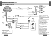
... surround processor (CY-AC300, option) ≥ Power amplifier (CY-M7052, option) ≥ Subwoofer (option) ≥ Center speaker (EAB-CF2, option) ≥ Video game (option) ≥ VCR, etc. (option) L (white) CQ-VA707WEUC Display Unit (option) Camcoder (option) R (red) Video (yellow) or VCR (option) MAIN-IN FRONT MAIN-IN REAR Note: ≥ For wiring, carefully read the operating instructions for the devices connected.
... surround processor (CY-AC300, option) ≥ Power amplifier (CY-M7052, option) ≥ Subwoofer (option) ≥ Center speaker (EAB-CF2, option) ≥ Video game (option) ≥ VCR, etc. (option) L (white) CQ-VA707WEUC Display Unit (option) Camcoder (option) R (red) Video (yellow) or VCR (option) MAIN-IN FRONT MAIN-IN REAR Note: ≥ For wiring, carefully read the operating instructions for the devices connected.


