Service Manual
Page 8
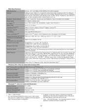
.../161/165 IEEE802.11b/IEEE802.11g: Channels 1 to 11 RF Frequency Band IEEE802.11a: 5.18-5.32 GHz, 5.745-5.825 GHz IEEE802.11b/IEEE802.11g: 2.412-2.462 GHz Bluetooth™ Bluetooth Version 2.0 + EDR Transmission method FHSS system Wireless Channels Used Channels 1 to 79 RF...), Microphone Jack (Miniature jack, 3.5 DIA, Stereo), Headphone Jack (Miniature jack, 3.5 DIA, Impedance 32 Ω, Output Power 4 mW × 2) Keyboard / Pointing Device 87 keys / Touch Pad / Touchscreen (Anti-Reflection, Stylus (included) touch capable) Power Supply AC adaptor or Battery pack AC Adaptor*19...
.../161/165 IEEE802.11b/IEEE802.11g: Channels 1 to 11 RF Frequency Band IEEE802.11a: 5.18-5.32 GHz, 5.745-5.825 GHz IEEE802.11b/IEEE802.11g: 2.412-2.462 GHz Bluetooth™ Bluetooth Version 2.0 + EDR Transmission method FHSS system Wireless Channels Used Channels 1 to 79 RF...), Microphone Jack (Miniature jack, 3.5 DIA, Stereo), Headphone Jack (Miniature jack, 3.5 DIA, Impedance 32 Ω, Output Power 4 mW × 2) Keyboard / Pointing Device 87 keys / Touch Pad / Touchscreen (Anti-Reflection, Stylus (included) touch capable) Power Supply AC adaptor or Battery pack AC Adaptor*19...

Service Manual
Page 10
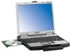
..., Blinking green rapidly: Cannot recorded. If other types H :LCD I C D O E P F Q A :Speaker J : Power switch B :USB port K :Function key C :Stylus holder L : Bluetooth antenna D :Multimedia pocket E : Hard disk drive M :Keyboard F : Carrying handle N :Touch pad G :Wireless LAN antenna O :Microphone jack A condenser microphone can connect headphones or amplified speakers. 2. Q :Wireless switch 2-1 Names and Functions of Parts G H I J K A A L M N B I : LED...
..., Blinking green rapidly: Cannot recorded. If other types H :LCD I C D O E P F Q A :Speaker J : Power switch B :USB port K :Function key C :Stylus holder L : Bluetooth antenna D :Multimedia pocket E : Hard disk drive M :Keyboard F : Carrying handle N :Touch pad G :Wireless LAN antenna O :Microphone jack A condenser microphone can connect headphones or amplified speakers. 2. Q :Wireless switch 2-1 Names and Functions of Parts G H I J K A A L M N B I : LED...
Service Manual
Page 14
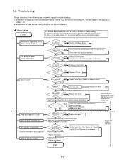
... Power lamp NO check YES Inverter board NG OK Replace AC Adaptor/Battery Check contact condition of trouble in starting NG Replace main board. Replace keyboard or main board. Each kind of power input terminal. Since flaws may appear on specific media, DVD or CD media can be turned ON', 'Set...
... Power lamp NO check YES Inverter board NG OK Replace AC Adaptor/Battery Check contact condition of trouble in starting NG Replace main board. Replace keyboard or main board. Each kind of power input terminal. Since flaws may appear on specific media, DVD or CD media can be turned ON', 'Set...
Service Manual
Page 15
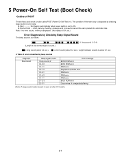
... OK, etc.) Error Diagnosis by beep sounds Diagnosis Main board Beep signal sound 1(long sound)-2 1-2-2-3 1-3-1-1 1-3-1-3 1-3-4-1 1-3-4-3 1-4-1-1 2-1-2-3 2-2-3-1 Error message BIOS ROM error BIOS ROM error RAM error Keyboard controller error RAM error RAM error RAM error BIOS ROM error Occurrence of unexpected offering (Note) A beep sound is also issued in it. z Table of...
... OK, etc.) Error Diagnosis by beep sounds Diagnosis Main board Beep signal sound 1(long sound)-2 1-2-2-3 1-3-1-1 1-3-1-3 1-3-4-1 1-3-4-3 1-4-1-1 2-1-2-3 2-2-3-1 Error message BIOS ROM error BIOS ROM error RAM error Keyboard controller error RAM error RAM error RAM error BIOS ROM error Occurrence of unexpected offering (Note) A beep sound is also issued in it. z Table of...
Service Manual
Page 16
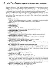
... wait states, improper Setup settings can display. Others may indicate a problem with an asterisk (*), write down the message and contact Panasonic Technical Support. Replace the battery and run SETUP The CMOS clock battery indicator shows the battery is correct. If you make changes ...The BIOS installed Default SETUP Values. Run Setup and verify that BIOS can also terminate POST and cause this error on keyboard. 0211 Keyboard error Keyboard not working or not configured properly. Default configuration used System CMOS has been corrupted or modified incorrectly, perhaps by POST...
... wait states, improper Setup settings can display. Others may indicate a problem with an asterisk (*), write down the message and contact Panasonic Technical Support. Replace the battery and run SETUP The CMOS clock battery indicator shows the battery is correct. If you make changes ...The BIOS installed Default SETUP Values. Run Setup and verify that BIOS can also terminate POST and cause this error on keyboard. 0211 Keyboard error Keyboard not working or not configured properly. Default configuration used System CMOS has been corrupted or modified incorrectly, perhaps by POST...

Service Manual
Page 22
CN1 DIMM MEMORY CARD CN8 CN2 CN3 LITHIUM BATTERY WIRELESS MODULE ANTENNA PCB R JK2 JK1 Headphone Microphone KBD FPC KEYBOARD PCMCIA SLOT CN26 CN13 HDD PACK CN1301 SW1304 SW1301 Connector by Cable Direct connection by Connectors Parts on Bottom Side PAD SW PCB CN1302 SW1303 ...
CN1 DIMM MEMORY CARD CN8 CN2 CN3 LITHIUM BATTERY WIRELESS MODULE ANTENNA PCB R JK2 JK1 Headphone Microphone KBD FPC KEYBOARD PCMCIA SLOT CN26 CN13 HDD PACK CN1301 SW1304 SW1301 Connector by Cable Direct connection by Connectors Parts on Bottom Side PAD SW PCB CN1302 SW1303 ...

Service Manual
Page 24
... (CN25) KBD FPC 5. Removing the Speaker and the LED PCB CN1002 Tape Speaker Holder Speaker L Sheet CN1003 LED PCB Tape Speaker Holder Speaker R Keyboard KBD Angle R 1. Remove the two tapes, and disconnect the two Speaker Cables from the Connector (CN25). 9. 9.1.4. Remove the KBD FPC, Hooks 1. KBD WP .... Screws : XSB2+3FNL 9.1.5. Lift the upper part of the Center Cover, and then remove the Center Cover. 3. Lift the upper part of the Keyboard and draw it backward, release the six Hooks fixing the front side of the Center Cover and draw it backward, and then turn the...
... (CN25) KBD FPC 5. Removing the Speaker and the LED PCB CN1002 Tape Speaker Holder Speaker L Sheet CN1003 LED PCB Tape Speaker Holder Speaker R Keyboard KBD Angle R 1. Remove the two tapes, and disconnect the two Speaker Cables from the Connector (CN25). 9. 9.1.4. Remove the KBD FPC, Hooks 1. KBD WP .... Screws : XSB2+3FNL 9.1.5. Lift the upper part of the Center Cover, and then remove the Center Cover. 3. Lift the upper part of the Keyboard and draw it backward, release the six Hooks fixing the front side of the Center Cover and draw it backward, and then turn the...

Service Manual
Page 45
.... 5. Hook the six front Hooks of the Main PCB. 2. 9.2.16. Insert the front Hooks of the Keyboard and the FPC to the computer, and set in the claws on the rear side of the dome. (two... contact of the Center Cover to the computer, and press the Center Cover to be securely set the Keyboard to the computer as it from being caught inside the dome. Hook the seven rear Hooks of two-...Connector (CN25) 4. Ensure the Cable does not run in the unit and avoid it covers the Cable of the Keyboard to the KBD Angle L and R. 7. Connect the KBD FPC Cable to the Connector (CN25) of the Center ...
.... 5. Hook the six front Hooks of the Main PCB. 2. 9.2.16. Insert the front Hooks of the Keyboard and the FPC to the computer, and set in the claws on the rear side of the dome. (two... contact of the Center Cover to the computer, and press the Center Cover to be securely set the Keyboard to the computer as it from being caught inside the dome. Hook the seven rear Hooks of two-...Connector (CN25) 4. Ensure the Cable does not run in the unit and avoid it covers the Cable of the Keyboard to the KBD Angle L and R. 7. Connect the KBD FPC Cable to the Connector (CN25) of the Center ...
Service Manual
Page 53
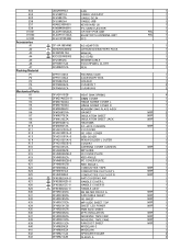
...K34 K35 K36 K37 K38 K39 K40 K41 K42 K43 UDQFRPH32 DFJS995YA DFJS987ZA DFJS992XA N2ABZJ000033 K1NB94BA0001 DL3UP1505AAA DL3UP1517AAA DFJK10T053DB S CF-AA1683AM3 S N4HUNTA00002 S DFQW5047ZA S K2CG3DR00003 DFJS954ZA DFHS9017ZA DFHR6207ZA DFPK1182YA DFPK1185ZA DFPE0827ZA DFPN0834ZA DFPN0835ZA DFUQ0110ZB DFMD7A65ZA-0 DFMD7A83ZA DFMD7A84ZA... DFHR3D05ZA DFHR3D06ZA DFHR3D08ZA DFHR3D10ZA DFHR3D13ZA DFHR6204ZA DFHR6205ZA DFHR6211ZA DFHR6213ZB FAN CABLE LAN ASSY CABLE DC IN CABLE USB KEYBOARD US PC CARD EJECTOR CF74 BT PCB UNIT BLUETOOTH ANTENNA UNIT FFC AC ADAPTOR LITHIUM ION BATTERY PACK MANUAL...
...K34 K35 K36 K37 K38 K39 K40 K41 K42 K43 UDQFRPH32 DFJS995YA DFJS987ZA DFJS992XA N2ABZJ000033 K1NB94BA0001 DL3UP1505AAA DL3UP1517AAA DFJK10T053DB S CF-AA1683AM3 S N4HUNTA00002 S DFQW5047ZA S K2CG3DR00003 DFJS954ZA DFHS9017ZA DFHR6207ZA DFPK1182YA DFPK1185ZA DFPE0827ZA DFPN0834ZA DFPN0835ZA DFUQ0110ZB DFMD7A65ZA-0 DFMD7A83ZA DFMD7A84ZA... DFHR3D05ZA DFHR3D06ZA DFHR3D08ZA DFHR3D10ZA DFHR3D13ZA DFHR6204ZA DFHR6205ZA DFHR6211ZA DFHR6213ZB FAN CABLE LAN ASSY CABLE DC IN CABLE USB KEYBOARD US PC CARD EJECTOR CF74 BT PCB UNIT BLUETOOTH ANTENNA UNIT FFC AC ADAPTOR LITHIUM ION BATTERY PACK MANUAL...