
Service Manual
Page 5
List of Parts 3. Wiring Connection Diagram 9. Disassembly/Reassembly 10. Power-On Self Test (Boot Check) 6. Block Diagram 4. Specifications 2. Replacement Parts List 1-1 2-1 3-1 4-1 5-1 6-1 7-1 8-1 9-1 10-1 11-1 CONTENTS 1. Exploded View 11. Diagnosis Procedure 5. Self Diagnosis Test 8. Names and Functions of Error Codes 7.
List of Parts 3. Wiring Connection Diagram 9. Disassembly/Reassembly 10. Power-On Self Test (Boot Check) 6. Block Diagram 4. Specifications 2. Replacement Parts List 1-1 2-1 3-1 4-1 5-1 6-1 7-1 8-1 9-1 10-1 11-1 CONTENTS 1. Exploded View 11. Diagnosis Procedure 5. Self Diagnosis Test 8. Names and Functions of Error Codes 7.
Service Manual
Page 8
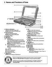
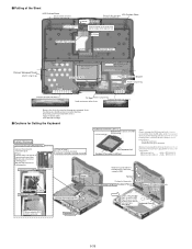
...key (NumLk) : Scroll lock (ScrLk) : Hard disk drive status F: Tablet Buttons Reference Manual "Tablet Buttons" G: LCD Reference Manual "Touchscreen" Reference Manual "Digitizer" H: Display Release Latch page 12 "Switching to the Tablet mode" I: Speaker Reference Manual "Key Combinations" J: Function Key Reference Manual... ion battery that is recyclable powers the product you have purchased. It does not necessarily indicate the On/Off condition of Parts A: Wireless LAN Antenna Reference Manual "Wireless LAN" B: Bluetooth Antenna Reference Manual "Bluetooth" C: Stylus/Pen Holder D: Touch...
...key (NumLk) : Scroll lock (ScrLk) : Hard disk drive status F: Tablet Buttons Reference Manual "Tablet Buttons" G: LCD Reference Manual "Touchscreen" Reference Manual "Digitizer" H: Display Release Latch page 12 "Switching to the Tablet mode" I: Speaker Reference Manual "Key Combinations" J: Function Key Reference Manual... ion battery that is recyclable powers the product you have purchased. It does not necessarily indicate the On/Off condition of Parts A: Wireless LAN Antenna Reference Manual "Wireless LAN" B: Bluetooth Antenna Reference Manual "Bluetooth" C: Stylus/Pen Holder D: Touch...
Service Manual
Page 16
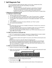
...If customer set . 4. " Yes" is displayed after doing the power supply switch in are possible. "Ctrl" + "F7" is pushed while the "Panasonic" start "PC-Diagnostic utility" again after the computer is also possible.) A flat pad does not work for a while after RAM begins from the CPU/System test, a ...and then takes notes of the content of the BIOS setup of setup 1. All devices which the customer who bought PC can select the enhancing test make the setting of the breakdown part. 7-1 The test begins clicking . *Please refer to "Invalidity" by "Advanced" or "Security" menu, becomes...
...If customer set . 4. " Yes" is displayed after doing the power supply switch in are possible. "Ctrl" + "F7" is pushed while the "Panasonic" start "PC-Diagnostic utility" again after the computer is also possible.) A flat pad does not work for a while after RAM begins from the CPU/System test, a ...and then takes notes of the content of the BIOS setup of setup 1. All devices which the customer who bought PC can select the enhancing test make the setting of the breakdown part. 7-1 The test begins clicking . *Please refer to "Invalidity" by "Advanced" or "Security" menu, becomes...
Service Manual
Page 22
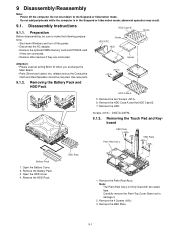
... Palm Rest Ass'y KBD Plate Battery Pack 1. Remove the KBD Plate. 9-1 abnormal operation may result. 9.1. Open the HDD Cover. 4. Use new parts. 9.1.2. HDD Case B HDD FPC Hooks HDD Hooks Heater Attention: • Please execute writing BIOS ID when you exchange the Main Board. •...; Parts (Sheet and rubber) etc. Remove the HDD Pack. Remove the Palm Rest Ass'y. Removing the Battery Pack and HDD Pack HDD Case A ...
... Palm Rest Ass'y KBD Plate Battery Pack 1. Remove the KBD Plate. 9-1 abnormal operation may result. 9.1. Open the HDD Cover. 4. Use new parts. 9.1.2. HDD Case B HDD FPC Hooks HDD Hooks Heater Attention: • Please execute writing BIOS ID when you exchange the Main Board. •...; Parts (Sheet and rubber) etc. Remove the HDD Pack. Remove the Palm Rest Ass'y. Removing the Battery Pack and HDD Pack HDD Case A ...
Service Manual
Page 30
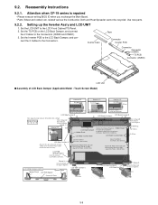
...Kgf) Order of fixing After setting LCD Back Damper, fix them together. Attention when CF-19 series is repaired • Please execute writing BIOS ID when you exchange the Main Board. • Parts (Sheet and rubber) etc. Setting up the Inverter Ass'y and LCD UNIT 1. ...LCD UNIT to the LCD Back Damper, and con- Set the Inverter PCB to the LCD Front Cabinet/TS Panel. 2. Use new parts. 9.2.2. 9.2. Reassembly Instructions 9.2.1. related various the Conductive Cloth and Heat Spreader cannot be recycled. Inverter Case Tape Connector Inverter PCB Connector Connector...
...Kgf) Order of fixing After setting LCD Back Damper, fix them together. Attention when CF-19 series is repaired • Please execute writing BIOS ID when you exchange the Main Board. • Parts (Sheet and rubber) etc. Setting up the Inverter Ass'y and LCD UNIT 1. ...LCD UNIT to the LCD Back Damper, and con- Set the Inverter PCB to the LCD Front Cabinet/TS Panel. 2. Use new parts. 9.2.2. 9.2. Reassembly Instructions 9.2.1. related various the Conductive Cloth and Heat Spreader cannot be recycled. Inverter Case Tape Connector Inverter PCB Connector Connector...
Service Manual
Page 31
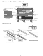
... n Assembly of hole and notch. Inverter MIL Cover Insert from the direction of Inverter PCB 0 0.5mm 0 0.5mm 0 0.5mm 0 0.5mm 2 0.5mm 10 2mm 0 0.5mm 0 0.5mm Important Parts for Safety Inverter Inverter Case Bottom Do not press the piezoelectric transformer. Confirm the direction of the Frame. n Assembly of LCD Back Damper (Application Model...
... n Assembly of hole and notch. Inverter MIL Cover Insert from the direction of Inverter PCB 0 0.5mm 0 0.5mm 0 0.5mm 0 0.5mm 2 0.5mm 10 2mm 0 0.5mm 0 0.5mm Important Parts for Safety Inverter Inverter Case Bottom Do not press the piezoelectric transformer. Confirm the direction of the Frame. n Assembly of LCD Back Damper (Application Model...
Service Manual
Page 32
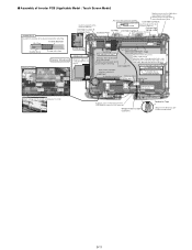
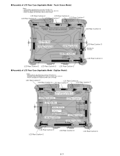
... Cable to the Tape left and right Connectors. LCD Side Cushion E 12 Connector Insert it . Fix the two Cables. Hold the Connector part when connecting/disconnecting. Wrap of the LCD Module because the line comes off. LCD Cable TS middle of the right and left sides on ...Conductive Tape Wind round the LCD Cable a few times and attach it between the ribs. (Fit to the Cabinet.) LCD Side Cushion E Insulation Parts Insulation Parts Avoid any stress on the Cable when connecting the CCFL Cable. Attach it . Safety Working 0 1mm LCD Ass'y Details of "A" Ensure the ...
... Cable to the Tape left and right Connectors. LCD Side Cushion E 12 Connector Insert it . Fix the two Cables. Hold the Connector part when connecting/disconnecting. Wrap of the LCD Module because the line comes off. LCD Cable TS middle of the right and left sides on ...Conductive Tape Wind round the LCD Cable a few times and attach it between the ribs. (Fit to the Cabinet.) LCD Side Cushion E Insulation Parts Insulation Parts Avoid any stress on the Cable when connecting the CCFL Cable. Attach it . Safety Working 0 1mm LCD Ass'y Details of "A" Ensure the ...
Service Manual
Page 37
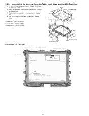
...as painting lump exists around D5. (Due to the Display Unit. 3. Attach the Antenna Covers and the Tablet Latch Cover to affect the Touch Screen operations.) Tablet Latch Cover Antenna Cover Insert it between the ribs, and attach it. LCD Rear Case 4. Attach here ...Position of the Display Unit. Assembling the Antenna Cover, the Tablet Latch Cover and the LCD Rear Case 1. 9.2.5. Fix the LCD Rear Case using the 10 Screws and the 2 Screws. 2. Attach and...
...as painting lump exists around D5. (Due to the Display Unit. 3. Attach the Antenna Covers and the Tablet Latch Cover to affect the Touch Screen operations.) Tablet Latch Cover Antenna Cover Insert it between the ribs, and attach it. LCD Rear Case 4. Attach here ...Position of the Display Unit. Assembling the Antenna Cover, the Tablet Latch Cover and the LCD Rear Case 1. 9.2.5. Fix the LCD Rear Case using the 10 Screws and the 2 Screws. 2. Attach and...
Service Manual
Page 38
... 0.5mm 0 to 1 mm from one of the lines. 0.5mm 0 1mm LCD Rear Cushion C LCD Rear Cushion C LCD Rear Ass'y Marking line 0.5mm Safety Working Important Parts for Safety Safety critical component LCD Rear Cushion C Marking line 0.5mm LCD Rear Cushion A LCD Rear Cushion E 0 3mm LCD Rear Cushion E LCD Rear Cushion C LCD...
... 0.5mm 0 to 1 mm from one of the lines. 0.5mm 0 1mm LCD Rear Cushion C LCD Rear Cushion C LCD Rear Ass'y Marking line 0.5mm Safety Working Important Parts for Safety Safety critical component LCD Rear Cushion C Marking line 0.5mm LCD Rear Cushion A LCD Rear Cushion E 0 3mm LCD Rear Cushion E LCD Rear Cushion C LCD...
Service Manual
Page 43
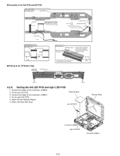
... on the back side. The Connector bracket is right when attaching. Connect the Cable to the Connector. (CN806) 2. n Assembly of the LED part, or running over the LED part. Attach the two Release Papers. 6. SW PCB Operation Sheet n Putting of the TP Bottom Tape Front side SW PCB Ass'y Match to 0.5mm...
... on the back side. The Connector bracket is right when attaching. Connect the Cable to the Connector. (CN806) 2. n Assembly of the LED part, or running over the LED part. Attach the two Release Papers. 6. SW PCB Operation Sheet n Putting of the TP Bottom Tape Front side SW PCB Ass'y Match to 0.5mm...
Service Manual
Page 50
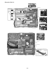
... FPC Lengthwise Attach it on the HDD Connector for about 1 second. Insert and then lock Thermal Rubber Fit it before setting the Main Board. Important Parts for spraying around when applying.) Connect Main PCB Ass'y Details of the FPC. 3mm Audio FPC Ass'y Insert it to the corner of the SD...
... FPC Lengthwise Attach it on the HDD Connector for about 1 second. Insert and then lock Thermal Rubber Fit it before setting the Main Board. Important Parts for spraying around when applying.) Connect Main PCB Ass'y Details of the FPC. 3mm Audio FPC Ass'y Insert it to the corner of the SD...
Service Manual
Page 55
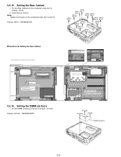
... wall. 0 to the marking line and attach it . Screws : DRHM5025YAT Tape DIMM Thermal Sheet Match to 1mm 0 1mm Tape Potre Blind Sheet Rated Label Important Parts for Safety Safety critical component Note for attachment Avoid running over the frame. Setting the DIMM Lid Ass'y 1. Note: Tighten the Screws in the numbered...
... wall. 0 to the marking line and attach it . Screws : DRHM5025YAT Tape DIMM Thermal Sheet Match to 1mm 0 1mm Tape Potre Blind Sheet Rated Label Important Parts for Safety Safety critical component Note for attachment Avoid running over the frame. Setting the DIMM Lid Ass'y 1. Note: Tighten the Screws in the numbered...
Service Manual
Page 57
...the Hinge side. The paste should be put pressure after setting the KBD. Because the sheets described on this page are waterproof sheets, the whole parts should be put the left side. Exchange LCD cable - Avoid running over. 0.5 to reuse the removed sheet, please leave it peels off once.... Do not bend at the foot of stiffening plate. Because KB connector Lid Sheet takes some time for Setting the Keyboard Safety Working Connect part the LCD CABLE/KBD FFC Connect the Connector to 0.5 mm Avoid running over other sheets. Remove/Exchange the Keyboard Moreover, if you do...
...the Hinge side. The paste should be put pressure after setting the KBD. Because the sheets described on this page are waterproof sheets, the whole parts should be put the left side. Exchange LCD cable - Avoid running over. 0.5 to reuse the removed sheet, please leave it peels off once.... Do not bend at the foot of stiffening plate. Because KB connector Lid Sheet takes some time for Setting the Keyboard Safety Working Connect part the LCD CABLE/KBD FFC Connect the Connector to 0.5 mm Avoid running over other sheets. Remove/Exchange the Keyboard Moreover, if you do...
Service Manual
Page 60
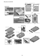
... width x 4 cm) Heater Insulation Sheet Attach on the inner side of Heater Insulation Sheet 0 0.5mm Note for the Heater top end location 0 1mm Insulation Parts 10 15mm Avoid any stress Insulation Parts Heater Assy 5 1mm Back 5 1mm HDD Connect the Connector Round to make the brown side outside and insert the notch... part FPC(HDD) Two-sided Tape Thermal Sheet 1 2mm HDD Case Lower Come the bottom over by 0 to 0.5 mm. Attach it on the center of the ...
... width x 4 cm) Heater Insulation Sheet Attach on the inner side of Heater Insulation Sheet 0 0.5mm Note for the Heater top end location 0 1mm Insulation Parts 10 15mm Avoid any stress Insulation Parts Heater Assy 5 1mm Back 5 1mm HDD Connect the Connector Round to make the brown side outside and insert the notch... part FPC(HDD) Two-sided Tape Thermal Sheet 1 2mm HDD Case Lower Come the bottom over by 0 to 0.5 mm. Attach it on the center of the ...
Service Manual
Page 69
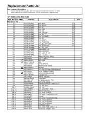
... Note : Important Safety Notice Components identified by ! CF-19CDBAXVM (2006/11/20) REF. When replacing any of these components, use only manufacturer's specified parts. NO and AREA PART NO. mark have special characteristics important for safety. Main Block Unit E1 DL3U11530AAA E2 DL3U21530AAA E3 DL3U31530AAA E4 DL3U11550BAA E5 DL3U21550BAA E6 DL3U31550BAA E7 DL3U41550BAA ...
... Note : Important Safety Notice Components identified by ! CF-19CDBAXVM (2006/11/20) REF. When replacing any of these components, use only manufacturer's specified parts. NO and AREA PART NO. mark have special characteristics important for safety. Main Block Unit E1 DL3U11530AAA E2 DL3U21530AAA E3 DL3U31530AAA E4 DL3U11550BAA E5 DL3U21550BAA E6 DL3U31550BAA E7 DL3U41550BAA ...
Service Manual
Page 70
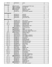
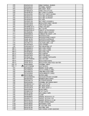
... S NCR-B/603A LITHIUM ION BATTERY PACK 1 A2 S CF-AA1633AM1 AC ADAPTOR 1 A3 S K2CG3DR00003 AC CORD 1 A4 S DFQX5624ZA MANUAL(CF-19MK1) 1 A5 DFJS954ZA MODEM CABLE 1 A6 DFHS9017ZA TOUCHPANEL FUKINUNO 1 Packing Material P1 DFPE0733YA HOLDER 1 P2 DFPE0859YA HOLDER 1 P3 DFPK1210ZA PACKING CASE 1 P4 DFPK1216YA ACCESSORY BOX 1 Mechanical Parts K1 DFHM9017ZA-0 EZC LID ASSY 1 K3 DFHR9125ZA...
... S NCR-B/603A LITHIUM ION BATTERY PACK 1 A2 S CF-AA1633AM1 AC ADAPTOR 1 A3 S K2CG3DR00003 AC CORD 1 A4 S DFQX5624ZA MANUAL(CF-19MK1) 1 A5 DFJS954ZA MODEM CABLE 1 A6 DFHS9017ZA TOUCHPANEL FUKINUNO 1 Packing Material P1 DFPE0733YA HOLDER 1 P2 DFPE0859YA HOLDER 1 P3 DFPK1210ZA PACKING CASE 1 P4 DFPK1216YA ACCESSORY BOX 1 Mechanical Parts K1 DFHM9017ZA-0 EZC LID ASSY 1 K3 DFHR9125ZA...
Service Manual
Page 72
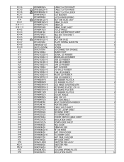
K13-4 DFHM0295ZA TABLET LATCH SHAFT 1 K13-5 S DFKE0892ZA-0 TABLET LATCH KNOB 1 K13-6 S DFKE0893ZA-0 TABLET LATCH LEVER 1 K13-7 DFNW1604ZA CUT WASHER 1 K13-8 DFUN0069XA LATCH KNOB SPRING 1 K14 ... RUBBER PLATE A 1 K28 DFHM0288ZB LID RUBBER PLATE C 2 K29 DFHM0296XA-0 LCD HINGE COVER(SILVER) 1 K30 DFHM0302XA-2 KEYBOARD PLATE(L) CF-19 1 K31 DFHM0303XA-0 KEYBOARD PLATE(R) 1 K32 DFHM0311ZB LID RUBBER PLATE B 2 K33 DFHM0403ZA DU CNT ANGLE 1 K34 DFHM0406ZA KBD CNT LID...TETHER 1 K53 DFMC0870ZA DU CONN SPRING PLATE 1 K54 DFMX0383TA INSULATION PARTS 18
K13-4 DFHM0295ZA TABLET LATCH SHAFT 1 K13-5 S DFKE0892ZA-0 TABLET LATCH KNOB 1 K13-6 S DFKE0893ZA-0 TABLET LATCH LEVER 1 K13-7 DFNW1604ZA CUT WASHER 1 K13-8 DFUN0069XA LATCH KNOB SPRING 1 K14 ... RUBBER PLATE A 1 K28 DFHM0288ZB LID RUBBER PLATE C 2 K29 DFHM0296XA-0 LCD HINGE COVER(SILVER) 1 K30 DFHM0302XA-2 KEYBOARD PLATE(L) CF-19 1 K31 DFHM0303XA-0 KEYBOARD PLATE(R) 1 K32 DFHM0311ZB LID RUBBER PLATE B 2 K33 DFHM0403ZA DU CNT ANGLE 1 K34 DFHM0406ZA KBD CNT LID...TETHER 1 K53 DFMC0870ZA DU CONN SPRING PLATE 1 K54 DFMX0383TA INSULATION PARTS 18
Service Manual
Page 73
... SHEET 30X140 1 K66 DFHR3G42ZA TAPE PEN HOLDER 1 K67 DFHR6081ZA-0 CABLE HOLDER 2 K68 DFHR6105XA-2 ANT COVER 2 K69 DFHR6279ZA-0 TABLET LATCH COVER 1 K70 DFHR6298ZA HINGE CABLE HOLDER 2 K71 DFMC0685ZA CONDUCTIVE SHEET, LCD 1 K73 DFMC0877YA INVERTER CASE 1 K74 DFMC0878ZA ... K80-5 DFHR3F54ZA HDD CON SHEET 1 K80-6 DFHR6297ZA HDD CONNECTOR GUARD 1 K80-7 DL3UP1564AAA HDD FPC UNIT 1 K80-8 DFMX0383TA INSULATION PARTS 2 K80-9 DFMX1265ZA INSULATION SHEET(HDD HEATER) 1 K80-10 DFMY3208ZA THERMAL SHEET 1 K80-11 S L9DZYY000008 HEATER(HDD) 1 K81...
... SHEET 30X140 1 K66 DFHR3G42ZA TAPE PEN HOLDER 1 K67 DFHR6081ZA-0 CABLE HOLDER 2 K68 DFHR6105XA-2 ANT COVER 2 K69 DFHR6279ZA-0 TABLET LATCH COVER 1 K70 DFHR6298ZA HINGE CABLE HOLDER 2 K71 DFMC0685ZA CONDUCTIVE SHEET, LCD 1 K73 DFMC0877YA INVERTER CASE 1 K74 DFMC0878ZA ... K80-5 DFHR3F54ZA HDD CON SHEET 1 K80-6 DFHR6297ZA HDD CONNECTOR GUARD 1 K80-7 DL3UP1564AAA HDD FPC UNIT 1 K80-8 DFMX0383TA INSULATION PARTS 2 K80-9 DFMX1265ZA INSULATION SHEET(HDD HEATER) 1 K80-10 DFMY3208ZA THERMAL SHEET 1 K80-11 S L9DZYY000008 HEATER(HDD) 1 K81...
Service Manual
Page 75
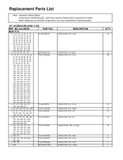
When replacing any of these components use only manufacturer's specified parts. MAIN PCB C 1, 2, 3, 6, 7, 8, 10, 11, 12, 14, 15, 16, 18, 19, 20, 22, 23, 24, 27, 28, 29, 30, 31, 32, 33, 34, 35, 36, 37, 38, 39, 40, 43, 51, 52, 55, 59, 60, 62, ..., 0.01µF CAPACITOR, 50V, 18pF CAPACITOR, 10V, 0.1µF CAPACITOR, 50V, 6.0pF CAPACITOR, 6.3V, 150µF Q'TY 64 6 149 10 6 18 20 29 2 7 2 1 NO and AREA PART NO. CF-19CDBAXVM (2006/11/20) REF. Replacement Parts List Note: Important Safety Notice Components identified by ! mark have special characteristics important for safety.
When replacing any of these components use only manufacturer's specified parts. MAIN PCB C 1, 2, 3, 6, 7, 8, 10, 11, 12, 14, 15, 16, 18, 19, 20, 22, 23, 24, 27, 28, 29, 30, 31, 32, 33, 34, 35, 36, 37, 38, 39, 40, 43, 51, 52, 55, 59, 60, 62, ..., 0.01µF CAPACITOR, 50V, 18pF CAPACITOR, 10V, 0.1µF CAPACITOR, 50V, 6.0pF CAPACITOR, 6.3V, 150µF Q'TY 64 6 149 10 6 18 20 29 2 7 2 1 NO and AREA PART NO. CF-19CDBAXVM (2006/11/20) REF. Replacement Parts List Note: Important Safety Notice Components identified by ! mark have special characteristics important for safety.
