Installation Guide
Page 1
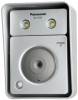
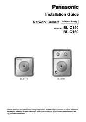
Panasonic Network Camera Website: http://panasonic.co.jp/pcc/products/en/netwkcam/ regionlinks/index.html Installation Guide Network Camera Outdoor Ready Model No. BL-C140 BL-C160 BL-C140 BL-C160 Please read this document before using the product, and save this document for future reference.
Panasonic Network Camera Website: http://panasonic.co.jp/pcc/products/en/netwkcam/ regionlinks/index.html Installation Guide Network Camera Outdoor Ready Model No. BL-C140 BL-C160 BL-C140 BL-C160 Please read this document before using the product, and save this document for future reference.
Installation Guide
Page 2
... camera by checking the model no . printed on the included CD-ROM. • This document (Installation Guide) explains how to physically connect the camera to the power supply and network, as "BL-C160 only" in this document. • The camera illustrations in this document, unless necessary. Available features and operations vary slightly depending on the CD-ROM if you have any problems configuring or using a PC. • Refer to the Operating Instructions...
... camera by checking the model no . printed on the included CD-ROM. • This document (Installation Guide) explains how to physically connect the camera to the power supply and network, as "BL-C160 only" in this document. • The camera illustrations in this document, unless necessary. Available features and operations vary slightly depending on the CD-ROM if you have any problems configuring or using a PC. • Refer to the Operating Instructions...
Installation Guide
Page 3
Table of Contents Installation Procedure Overview 4 Preparation 5 Camera Diagrams 7 Choosing an Installation Location 9 Detection Features...9 Mounting Location...13 Recommended Installation Locations 14 Installation Examples ...15 Light Brightness (BL-C160 Only 16 Effect of Brightness and Distance on Image Quality 16 Connections 17 Camera Mounting 18 Adjusting Range and Sensitivity 23 Preventing Sensor Interference (BL-C160 Only 23 Adjusting Motion Detection Sensitivity 25 Adjusting Sensor Sensitivity (BL-C160 Only 26 Sensor Range Caps (BL-C160 Only 27 3
Table of Contents Installation Procedure Overview 4 Preparation 5 Camera Diagrams 7 Choosing an Installation Location 9 Detection Features...9 Mounting Location...13 Recommended Installation Locations 14 Installation Examples ...15 Light Brightness (BL-C160 Only 16 Effect of Brightness and Distance on Image Quality 16 Connections 17 Camera Mounting 18 Adjusting Range and Sensitivity 23 Preventing Sensor Interference (BL-C160 Only 23 Adjusting Motion Detection Sensitivity 25 Adjusting Sensor Sensitivity (BL-C160 Only 26 Sensor Range Caps (BL-C160 Only 27 3
Installation Guide
Page 4
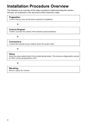
... accessed from a PC. Setup Setup the camera (described in this document unless otherwise noted. This involves configuring the camera so that you know the names of the steps required to the power outlet. Camera Diagram Confirm you have all the items required for installation. Mounting Mount or place the camera. 4 Installation Procedure Overview The following is an overview of the camera's physical features. Connections Connect...
... accessed from a PC. Setup Setup the camera (described in this document unless otherwise noted. This involves configuring the camera so that you know the names of the steps required to the power outlet. Camera Diagram Confirm you have all the items required for installation. Mounting Mount or place the camera. 4 Installation Procedure Overview The following is an overview of the camera's physical features. Connections Connect...
Installation Guide
Page 5
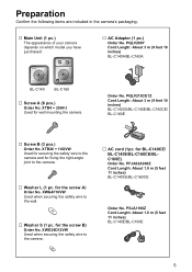
...: About 3 m (9 feet 10 inches) BL-C140A/BL-C160A BL-C140 BL-C160 … Screw A (6 pcs.) Order No. XTB26 + 10GVW Used for securing the safety wire to the camera and for fixing the right-angle joint to the wall. … Washer S (1 pc. for BL-C140CE/ BL-C140E/BL-C160CE/BLC160E) Order No. XWG4F16VW Used when securing the safety wire to the camera. … Washer L (1 pc...
...: About 3 m (9 feet 10 inches) BL-C140A/BL-C160A BL-C140 BL-C160 … Screw A (6 pcs.) Order No. XTB26 + 10GVW Used for securing the safety wire to the camera and for fixing the right-angle joint to the wall. … Washer S (1 pc. for BL-C140CE/ BL-C140E/BL-C160CE/BLC160E) Order No. XWG4F16VW Used when securing the safety wire to the camera. … Washer L (1 pc...
Installation Guide
Page 6
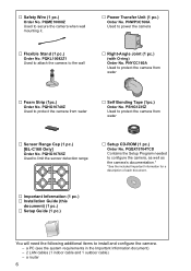
... Information document) - 2 LAN cables (1 indoor cable and 1 outdoor cable) - PNWP3C160A Used to secure the camera when wall mounting it. … Power Transfer Unit (1 pc.) Order No. a router 6 PQQX15704TCD Contains the Setup Program needed to configure the camera, as well as the camera's documentation.* *See the included Important Information for a description of each document. … Important Information (1 pc.) … Installation Guide (this document) (1 pc.) … Setup Guide (1 pc.) You will need the...
... Information document) - 2 LAN cables (1 indoor cable and 1 outdoor cable) - PNWP3C160A Used to secure the camera when wall mounting it. … Power Transfer Unit (1 pc.) Order No. a router 6 PQQX15704TCD Contains the Setup Program needed to configure the camera, as well as the camera's documentation.* *See the included Important Information for a description of each document. … Important Information (1 pc.) … Installation Guide (this document) (1 pc.) … Setup Guide (1 pc.) You will need the...
Installation Guide
Page 7
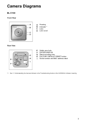
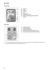
Camera Diagrams BL-C140 Front View A A Housing B B Indicator*1 C Lens D Lens cover C D Rear View E F E Safety wire hole F DATA/POWER IN G G Stand mounting hole H FACTORY DEFAULT RESET button H I Serial number and MAC address label I *1 See 1.1 Understanding the Camera Indicator in the Troubleshooting Guide on the CD-ROM for indicator meaning. 7
Camera Diagrams BL-C140 Front View A A Housing B B Indicator*1 C Lens D Lens cover C D Rear View E F E Safety wire hole F DATA/POWER IN G G Stand mounting hole H FACTORY DEFAULT RESET button H I Serial number and MAC address label I *1 See 1.1 Understanding the Camera Indicator in the Troubleshooting Guide on the CD-ROM for indicator meaning. 7
Installation Guide
Page 8
BL-C160 Front View A Housing A B Light C Indicator*1 B D Lens E Lens cover C F Brightness sensor*2 G Built-in sensor (pyroelectric infrared D sensor) E F G Rear View H I H Safety wire hole I DATA/POWER IN J Stand mounting hole K FACTORY DEFAULT RESET button L Serial number and MAC address label J K L *1 See 1.1 Understanding the Camera Indicator in the Troubleshooting Guide on the CD-ROM for indicator meaning. *2 The brightness sensor determines when the light turns on. 8
BL-C160 Front View A Housing A B Light C Indicator*1 B D Lens E Lens cover C F Brightness sensor*2 G Built-in sensor (pyroelectric infrared D sensor) E F G Rear View H I H Safety wire hole I DATA/POWER IN J Stand mounting hole K FACTORY DEFAULT RESET button L Serial number and MAC address label J K L *1 See 1.1 Understanding the Camera Indicator in the Troubleshooting Guide on the CD-ROM for indicator meaning. *2 The brightness sensor determines when the light turns on. 8
Installation Guide
Page 9
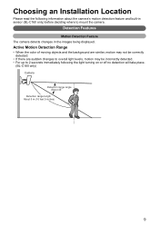
... correctly detected. • If there are sudden changes to overall light levels, motion may be incorrectly detected. • For up to mount the camera. Choosing an Installation Location Please read the following the light turning on or off no detection will take place. (BL-C160 only) Camera Detection range angle About 45q Detection range length About 5 m (16 feet 5 inches) 9 Detection Features Motion Detection Feature The camera detects changes in sensor (BL-C160...
... correctly detected. • If there are sudden changes to overall light levels, motion may be incorrectly detected. • For up to mount the camera. Choosing an Installation Location Please read the following the light turning on or off no detection will take place. (BL-C160 only) Camera Detection range angle About 45q Detection range length About 5 m (16 feet 5 inches) 9 Detection Features Motion Detection Feature The camera detects changes in sensor (BL-C160...
Installation Guide
Page 11
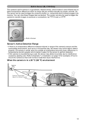
... that are emitted naturally by FTP, E-mail, or HTTP. Built-in Sensor (BL-C160 Only) The camera's built-in a 20 °C (68 °F) environment Camera Detection range angle About 20q Detection range length About 5 m (16 feet 5 inches) 11 The sensor can also be used to trigger the camera to transfer images to buffer (i.e., temporarily store) camera images in its range that cause...
... that are emitted naturally by FTP, E-mail, or HTTP. Built-in Sensor (BL-C160 Only) The camera's built-in a 20 °C (68 °F) environment Camera Detection range angle About 20q Detection range length About 5 m (16 feet 5 inches) 11 The sensor can also be used to trigger the camera to transfer images to buffer (i.e., temporarily store) camera images in its range that cause...
Installation Guide
Page 13
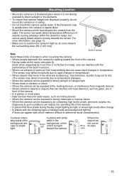
... types of backgrounds and background lighting (Faces can appear dark which makes it is not directly exposed to direct sunlight or the elements. • To ensure that move in the wind are located (e.g., tree branches, laundry hung out to dry) (The sensor may detect incorrectly due to rapid changes in temperature) • Where objects that camera images...
... types of backgrounds and background lighting (Faces can appear dark which makes it is not directly exposed to direct sunlight or the elements. • To ensure that move in the wind are located (e.g., tree branches, laundry hung out to dry) (The sensor may detect incorrectly due to rapid changes in temperature) • Where objects that camera images...
Installation Guide
Page 14
A sensor range cap can be attached to the camera to detect Side View Camera Entrance Height About 3 m (9 feet 10 inches) Distance About 3 m (9 feet 10 inches) 14 Difficult to detect Distance About 3 m (9 feet 10 inches) Camera Easy to control the detection range. Recommended Installation Locations Top View Where it is easier to detect people when they pass in front of the camera. For more information, see page 27. It is easy to detect people coming off the street towards the property and where passing cars do not cause interference.
A sensor range cap can be attached to the camera to detect Side View Camera Entrance Height About 3 m (9 feet 10 inches) Distance About 3 m (9 feet 10 inches) 14 Difficult to detect Distance About 3 m (9 feet 10 inches) Camera Easy to control the detection range. Recommended Installation Locations Top View Where it is easier to detect people when they pass in front of the camera. For more information, see page 27. It is easy to detect people coming off the street towards the property and where passing cars do not cause interference.
Installation Guide
Page 15
... by walking toward the front of the camera. It is easier to detect people when they can view over parked cars, or other objects in front of the camera are difficult to detect. Difficult to detect Street Easy to detect Street Easy to detect Camera Easy to detect Difficult to detect, but people approaching the camera by on the street will be...
... by walking toward the front of the camera. It is easier to detect people when they can view over parked cars, or other objects in front of the camera are difficult to detect. Difficult to detect Street Easy to detect Street Easy to detect Camera Easy to detect Difficult to detect, but people approaching the camera by on the street will be...
Installation Guide
Page 16
... it is Light dark, or when the camera's motion detection or sensor features are measured 3 m (9 feet 10 inches) from the camera (Generally, faces should be recognized.) • In the late afternoon and at night, or other variables, such as shadowing, backlight, angle, etc., may not provide enough light to 3 m [9 feet 10 inches] away, however, other times when the...
... it is Light dark, or when the camera's motion detection or sensor features are measured 3 m (9 feet 10 inches) from the camera (Generally, faces should be recognized.) • In the late afternoon and at night, or other variables, such as shadowing, backlight, angle, etc., may not provide enough light to 3 m [9 feet 10 inches] away, however, other times when the...
Installation Guide
Page 17
Also confirm that your router's UPnP™ feature is enabled. (Most routers have UPnP™ turned off by default.) Outside Wall Inside AC adaptor To the power outlet (For BL-C140CE/ BL-C140E/ BL-C160CE/ BL-C160E use an AC cord) Power transfer unit Outdoor LAN cable* LAN cable Router * Use a LAN cable that your PC is connected to your router and to the power outlet as described below...
Also confirm that your router's UPnP™ feature is enabled. (Most routers have UPnP™ turned off by default.) Outside Wall Inside AC adaptor To the power outlet (For BL-C140CE/ BL-C140E/ BL-C160CE/ BL-C160E use an AC cord) Power transfer unit Outdoor LAN cable* LAN cable Router * Use a LAN cable that your PC is connected to your router and to the power outlet as described below...
Installation Guide
Page 18
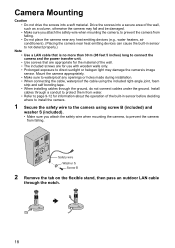
...sunlight or halogen light may damage the camera's image sensor. Safety wire Washer S Screw B 2 Remove the tab on the flexible stand, then pass an outdoor LAN cable through the ground, do not connect cables under the ground. Drive the screws into a soft material. Install cables through a ...detect properly.) Note • Use a LAN cable that is no more than 30 m (98 feet 5 inches) long to connect the camera and the power transfer unit. • Use screws that are for the material of the built-in sensor before deciding where to install the camera. 1 Secure the safety wire to the camera using...
...sunlight or halogen light may damage the camera's image sensor. Safety wire Washer S Screw B 2 Remove the tab on the flexible stand, then pass an outdoor LAN cable through the ground, do not connect cables under the ground. Drive the screws into a soft material. Install cables through a ...detect properly.) Note • Use a LAN cable that is no more than 30 m (98 feet 5 inches) long to connect the camera and the power transfer unit. • Use screws that are for the material of the built-in sensor before deciding where to install the camera. 1 Secure the safety wire to the camera using...
Installation Guide
Page 19
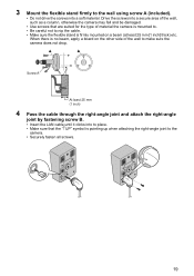
...is no beam, apply a board on a beam (at least 25 mm [1 inch] thick) etc. Drive the screws into a secure area of the wall, such as a column, otherwise the camera may fall and be damaged. • Use screws that the "↑UP" symbol is pointing up when attaching the right-angle joint to... the camera. • Securely fasten all screws. 19 When there is firmly mounted on the other side of material the camera is mounted to. •...
...is no beam, apply a board on a beam (at least 25 mm [1 inch] thick) etc. Drive the screws into a secure area of the wall, such as a column, otherwise the camera may fall and be damaged. • Use screws that the "↑UP" symbol is pointing up when attaching the right-angle joint to... the camera. • Securely fasten all screws. 19 When there is firmly mounted on the other side of material the camera is mounted to. •...
Installation Guide
Page 21
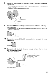
... the camera to the power transfer unit. 11 Connect the AC adaptor to the switching hub, router, etc. • The power transfer unit can be fixed in the safety wire, as shown. 8 Secure the safety wire to the wall using screw A (included) and washer L (included). • When mounting to a hard surface like mortar or concrete, use an AC cord) Hook...
... the camera to the power transfer unit. 11 Connect the AC adaptor to the switching hub, router, etc. • The power transfer unit can be fixed in the safety wire, as shown. 8 Secure the safety wire to the wall using screw A (included) and washer L (included). • When mounting to a hard surface like mortar or concrete, use an AC cord) Hook...
Installation Guide
Page 26
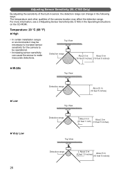
... (BL-C160 Only) By adjusting the sensitivity of the camera location may be necessary to increase sensor sensitivity for the camera to make inaccurate detections. The temperature and other qualities of the built-in sensor, the detection range can cause the sensor to be operational. • Increasing sensor sensitivity can change in the Operating Instructions on the CD-ROM. Top View Detection range...
... (BL-C160 Only) By adjusting the sensitivity of the camera location may be necessary to increase sensor sensitivity for the camera to make inaccurate detections. The temperature and other qualities of the built-in sensor, the detection range can cause the sensor to be operational. • Increasing sensor sensitivity can change in the Operating Instructions on the CD-ROM. Top View Detection range...
Installation Guide
Page 28
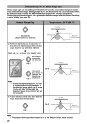
... side than with cap 2, attach cap 1. Note • If there are a guide to the detection ranges when the Sensor Sensitivity is set to prevent detections when the temperature changes in certain areas of the detention range, attach cap 3 as shown in the following...number is blocked. 28 Detection Ranges for the Sensor Range Caps Sensor range caps can detect within the detection range. Top View About 5 m (16 feet 5 inches) Cap 3 Cap 3 Detection range About 5 m (16 feet 5 inches) Note • The position of the cap determines the area of the detection range that you want to be used...
... side than with cap 2, attach cap 1. Note • If there are a guide to the detection ranges when the Sensor Sensitivity is set to prevent detections when the temperature changes in certain areas of the detention range, attach cap 3 as shown in the following...number is blocked. 28 Detection Ranges for the Sensor Range Caps Sensor range caps can detect within the detection range. Top View About 5 m (16 feet 5 inches) Cap 3 Cap 3 Detection range About 5 m (16 feet 5 inches) Note • The position of the cap determines the area of the detection range that you want to be used...


