AWPH400 User Guide
Page 4
... $ Assembling the pan/tilt head 12 $ Setting the mounting direction switch 14 $ Setting the PCB switches 15 $ Installing the pan/tilt head 16 $ Mounting the camera 17 $ Attaching the wire 18 Replacing the consumable parts 19 Specifications 20 AW-RC400 Cable Compensation Unit 38 Introduction 38 Accessories 38 Parts and their...
... $ Assembling the pan/tilt head 12 $ Setting the mounting direction switch 14 $ Setting the PCB switches 15 $ Installing the pan/tilt head 16 $ Mounting the camera 17 $ Attaching the wire 18 Replacing the consumable parts 19 Specifications 20 AW-RC400 Cable Compensation Unit 38 Introduction 38 Accessories 38 Parts and their...
AWPH400 User Guide
Page 6
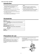
... AW-RP605A controller. ≥ In order to protect the environment when the pan/tilt head is to be discarded at high speeds of up to 50 positions can be registered as a camera and lens with the general household garbage. Do not throw out the battery along with a total weight of 17.6 lbs... indoor pan/tilt head can be rotated through 300 degrees in the vertical direction and 400 degrees in the horizontal direction. ≥ Operations can be performed at the end of its printed circuit boards, be absolutely sure to remove the battery. Before discarding the pan/tilt head or its service life...
... AW-RP605A controller. ≥ In order to protect the environment when the pan/tilt head is to be discarded at high speeds of up to 50 positions can be registered as a camera and lens with the general household garbage. Do not throw out the battery along with a total weight of 17.6 lbs... indoor pan/tilt head can be rotated through 300 degrees in the vertical direction and 400 degrees in the horizontal direction. ≥ Operations can be performed at the end of its printed circuit boards, be absolutely sure to remove the battery. Before discarding the pan/tilt head or its service life...
AWPH400 User Guide
Page 7
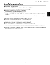
... may give rise to malfunctioning. ≥ Leave a clearance of at least 3.3 ft (1 meter) from around the monitor when installing the unit. ≥ When mounting the camera on the unit, take sufficient steps to be hotter than 113°F (45°C) or colder than 17.6 lbs (8 kg), it cannot be used if...or fall onto the floor. ≥ Install the unit in the kitchen and other locations with lots of steam and oily vapors. ≥ Mount the camera on it. ≥ Do not install the unit outdoors or in places where the humidity is below 90%. ≥ Purchase the mounting screws separately since...
... may give rise to malfunctioning. ≥ Leave a clearance of at least 3.3 ft (1 meter) from around the monitor when installing the unit. ≥ When mounting the camera on the unit, take sufficient steps to be hotter than 113°F (45°C) or colder than 17.6 lbs (8 kg), it cannot be used if...or fall onto the floor. ≥ Install the unit in the kitchen and other locations with lots of steam and oily vapors. ≥ Mount the camera on it. ≥ Do not install the unit outdoors or in places where the humidity is below 90%. ≥ Purchase the mounting screws separately since...
AWPH400 User Guide
Page 9
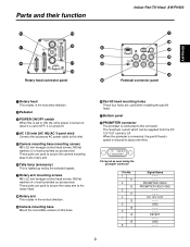
... is set to OFF, it is turned off. 4 AC 120 inlet [AC IN] (AC 3-point inlet) Connect the accessory AC power cable to this inlet. 5 Camera mounting base mounting screws M5!22 mm hexagon socket head screws, M5 flat washers (3 of each provided as accessories) These parts are used to secure.... 2 Pedestal 3 POWER ON/OFF switch When this is set to this base. : Pan/tilt head mounting holes These four holes are used to secure the camera mounting base to the rotary arm. 6 Tally lamp (accessory) This is reduced to about one-third. 87654321 ?>= The maximum current which can be supplied from...
... is set to OFF, it is turned off. 4 AC 120 inlet [AC IN] (AC 3-point inlet) Connect the accessory AC power cable to this inlet. 5 Camera mounting base mounting screws M5!22 mm hexagon socket head screws, M5 flat washers (3 of each provided as accessories) These parts are used to secure.... 2 Pedestal 3 POWER ON/OFF switch When this is set to this base. : Pan/tilt head mounting holes These four holes are used to secure the camera mounting base to the rotary arm. 6 Tally lamp (accessory) This is reduced to about one-third. 87654321 ?>= The maximum current which can be supplied from...
AWPH400 User Guide
Page 10
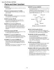
...) F TALLY OFF/ON switch [TALLY] When this is set to ON, the tally lamp is lighted by the selected signals. D CAMERA I/F connector [CAMERA I CABLE COMP OFF/ON switch [CABLE COMP] When this switch is connected to connect the lens with the AW-RC400 cable compensation unit.../focus) control cable to the SDI OUT connector on the AW-PB504 SDI card or other card installed in conjunction with the connector. Use the camera cable supplied with the REMOTE connector on the functions of the motorized lens unit. A LENS I/F (2) connector [LENS I /F (1)] This is required. C LENS I/F (1) ...
...) F TALLY OFF/ON switch [TALLY] When this is set to ON, the tally lamp is lighted by the selected signals. D CAMERA I/F connector [CAMERA I CABLE COMP OFF/ON switch [CABLE COMP] When this switch is connected to connect the lens with the AW-RC400 cable compensation unit.../focus) control cable to the SDI OUT connector on the AW-PB504 SDI card or other card installed in conjunction with the connector. Use the camera cable supplied with the REMOTE connector on the functions of the motorized lens unit. A LENS I/F (2) connector [LENS I /F (1)] This is required. C LENS I/F (1) ...

AWPH400 User Guide
Page 11
... OUT connector on the AW-RC400 cable compensation unit or monitor, etc. O Pb connector [Pb] This is the output connector for the camera's video signals. It is used . Use a BNC coaxial cable for the connecting cable. AW-PH400 Parts and their function J Y connector... [Y] This is the output connector for the camera's video signals. Use a BNC coaxial cable for the connecting cable. K 1394 connector [1394] This is connected to this connector. N PROMPTER IN...
... OUT connector on the AW-RC400 cable compensation unit or monitor, etc. O Pb connector [Pb] This is the output connector for the camera's video signals. It is used . Use a BNC coaxial cable for the connecting cable. AW-PH400 Parts and their function J Y connector... [Y] This is the output connector for the camera's video signals. Use a BNC coaxial cable for the connecting cable. K 1394 connector [1394] This is connected to this connector. N PROMPTER IN...

AWPH400 User Guide
Page 12
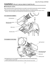
... base to the rotary head using the three mounting screws (M5!22 mm, with flat washers) provided. Camera Mounting base Change the positions of the camera mounting screws. Rotary head Camera mounting base 12 Indoor Pan/Tilt Head AW-PH400 Installation (Be sure to ask your dealer to the rotary... arm. The installation direction differs depending on the right, and then attach the camera mounting base to install the unit.) $ Assembling the pan/tilt head When assembling the pan/tilt head, use the Allen key (provided) and...
... base to the rotary head using the three mounting screws (M5!22 mm, with flat washers) provided. Camera Mounting base Change the positions of the camera mounting screws. Rotary head Camera mounting base 12 Indoor Pan/Tilt Head AW-PH400 Installation (Be sure to ask your dealer to the rotary... arm. The installation direction differs depending on the right, and then attach the camera mounting base to install the unit.) $ Assembling the pan/tilt head When assembling the pan/tilt head, use the Allen key (provided) and...
AWPH400 User Guide
Page 16
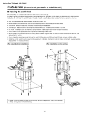
...accidents resulting when the product becomes dislodged or falls down, be ensured. ≥ After the pan/tilt head has been installed, mount the camera on it will not make contact with the bolts, and then anchor them securely to bear the weight of the entire pan/tilt head (pan.../tilt head, camera and lens cable). ≥ Install the pan/tilt head in malfunctioning. 16 For a stand-alone installation For installation on its side since its prescribed operation and performance cannot be absolutely sure to install the unit.) $ Installing the pan...
...accidents resulting when the product becomes dislodged or falls down, be ensured. ≥ After the pan/tilt head has been installed, mount the camera on it will not make contact with the bolts, and then anchor them securely to bear the weight of the entire pan/tilt head (pan.../tilt head, camera and lens cable). ≥ Install the pan/tilt head in malfunctioning. 16 For a stand-alone installation For installation on its side since its prescribed operation and performance cannot be absolutely sure to install the unit.) $ Installing the pan...
AWPH400 User Guide
Page 17
...screws. Rubber piece Mounting screws For installation on the pan/tilt head, be very careful to tighten the two camera mounting screws so that the camera is secured firmly. ❈ After the camera has been mounted, check that they are securely tightened. AW-PH400 Indoor Pan/Tilt Head AW-PH400 Installation ...(Be sure to ask your dealer.) 2 Insert the rubber piece between the camera and pan/tilt head, and mount the convertible camera after aligning it was mounted. Use a tool to tighten up the mounting screws so that there is no play in...
...screws. Rubber piece Mounting screws For installation on the pan/tilt head, be very careful to tighten the two camera mounting screws so that the camera is secured firmly. ❈ After the camera has been mounted, check that they are securely tightened. AW-PH400 Indoor Pan/Tilt Head AW-PH400 Installation ...(Be sure to ask your dealer.) 2 Insert the rubber piece between the camera and pan/tilt head, and mount the convertible camera after aligning it was mounted. Use a tool to tighten up the mounting screws so that there is no play in...

AWPH400 User Guide
Page 18
... washer and spring washer) to attach one end of the wire to the pan/tilt head's arm. 2 Mount the mounting spacer on the ceiling ≥ Camera: AW-E750 M4!8 mm wire mounting screw with flat washer and spring washer M4!6 mm wire mounting screw with flat washer and spring washer Mounting... with AW-E750) ❈ Be absolutely sure to tighten up the mounting spacer and screws securely using a tool such as a screwdriver. 18 When mounting the cameras without fan (AW-E350, AW-E650, AW-E300, AW-E300A, AW-E600) 1 Use the wire mounting screw (M4!8 mm with flat washer and spring washer...
... washer and spring washer) to attach one end of the wire to the pan/tilt head's arm. 2 Mount the mounting spacer on the ceiling ≥ Camera: AW-E750 M4!8 mm wire mounting screw with flat washer and spring washer M4!6 mm wire mounting screw with flat washer and spring washer Mounting... with AW-E750) ❈ Be absolutely sure to tighten up the mounting spacer and screws securely using a tool such as a screwdriver. 18 When mounting the cameras without fan (AW-E350, AW-E650, AW-E300, AW-E300A, AW-E600) 1 Use the wire mounting screw (M4!8 mm with flat washer and spring washer...

AWPH400 User Guide
Page 20
... V, 60 Hz Power consumption: 145 W 1 indicates safety information. The tilt range is limited to 190 degrees by the initial setting of camera to change the AW-RP400 setting. Genlock input: BNC Black burst or composite video signal Prompter input (PROMPTER IN): BNC Through output to ... BNC, 75-ohm output BNC, 75-ohm output BNC Camera, pan/tilt head control: RP/IP RJ45, RS-485, pan/tilt head control signal output Connecting cable: 10BASE-T straight cable (equivalent to UTP category 5), max. 500 meters Functions/performance: Maximum load-bearing capacity: 17.6 lbs (8 kg) Tilt...
... V, 60 Hz Power consumption: 145 W 1 indicates safety information. The tilt range is limited to 190 degrees by the initial setting of camera to change the AW-RP400 setting. Genlock input: BNC Black burst or composite video signal Prompter input (PROMPTER IN): BNC Through output to ... BNC, 75-ohm output BNC, 75-ohm output BNC Camera, pan/tilt head control: RP/IP RJ45, RS-485, pan/tilt head control signal output Connecting cable: 10BASE-T straight cable (equivalent to UTP category 5), max. 500 meters Functions/performance: Maximum load-bearing capacity: 17.6 lbs (8 kg) Tilt...
AWPH400 User Guide
Page 22
... heads to be controlled. ≥ By connecting the AW-CB400 remote operation panel or WV-CB700A remote control box to the control panel, the convertible cameras mounted on the pan/tilt heads can be controlled at the same time. ≥ By installing an additional control panel, two of the five units...
... heads to be controlled. ≥ By connecting the AW-CB400 remote operation panel or WV-CB700A remote control box to the control panel, the convertible cameras mounted on the pan/tilt heads can be controlled at the same time. ≥ By installing an additional control panel, two of the five units...

AWPH400 User Guide
Page 23
... not touch the joystick or zoom switch while this switch is set to [OFF], the power supply from the connected pan/tilt heads to the cameras is turned off when the switch is set to OFF. 3 OPERATE [OFF/ON] switch When this switch is at the [M] (master) position. Parts and their... additional AW-RP400 control panel is installed and used, it is set to [ON], the power supply from the connected pan/tilt heads to the cameras is turned on, and system control is enabled. It goes off . When an additional AW-RP400 control panel has been installed, set to [ON...
... not touch the joystick or zoom switch while this switch is set to [OFF], the power supply from the connected pan/tilt heads to the cameras is turned off when the switch is set to OFF. 3 OPERATE [OFF/ON] switch When this switch is at the [M] (master) position. Parts and their... additional AW-RP400 control panel is installed and used, it is set to [ON], the power supply from the connected pan/tilt heads to the cameras is turned on, and system control is enabled. It goes off . When an additional AW-RP400 control panel has been installed, set to [ON...

AWPH400 User Guide
Page 24
.../MANU/LOCK] button Use this to select the method for adjusting the lens iris of the cameras in the horizontal rotational direction for 200 degrees to the left or right. The pan/tilt head and camera setting can be controlled even when the (9) IRIS dial is turned. ≥ The IRIS button on..." and "AF" functions can be stored on the WV-CB700A. : ZOOM lever/FOCUS dial Use the ZOOM lever to adjust the lens zoom. AUTO: The cameras automatically adjust the lens iris in the sequence of the lever. ; It does not move the pan/tilt head and roll unit to the right...
.../MANU/LOCK] button Use this to select the method for adjusting the lens iris of the cameras in the horizontal rotational direction for 200 degrees to the left or right. The pan/tilt head and camera setting can be controlled even when the (9) IRIS dial is turned. ≥ The IRIS button on..." and "AF" functions can be stored on the WV-CB700A. : ZOOM lever/FOCUS dial Use the ZOOM lever to adjust the lens zoom. AUTO: The cameras automatically adjust the lens iris in the sequence of the lever. ; It does not move the pan/tilt head and roll unit to the right...

AWPH400 User Guide
Page 25
... OUT connector on this control panel is connected to the MONI SEL IN connector on the AW-RC400 cable compensation unit, the images of the camera connected to the MONI1 or MONI2 connector on the AW-RC400 can be set on the front of the AW-CB400 remote operation panel, if...
... OUT connector on this control panel is connected to the MONI SEL IN connector on the AW-RC400 cable compensation unit, the images of the camera connected to the MONI1 or MONI2 connector on the AW-RC400 can be set on the front of the AW-CB400 remote operation panel, if...

AWPH400 User Guide
Page 26
...WV-CB700A boxes have been connected can then be provided, connect these connectors. The cameras installed on the control panel or pan/tilt head lights. When even one WV-CB700A box is connected, the... cameras cannot be controlled from the AW-CB400 remote operation panel even if the AW-CB400 is set... panel AW-RP400 EXT CONT IN EXT CONT IN EXT CONT OUT 10BASE-T 10BASE-T straight cable EXT CONT OUT N CAMERA CONTROL IN FROM RCB [P1] to [P5] connectors Connect the WV-CB700A remote control boxes to the TALLY/INCOM ...
...WV-CB700A boxes have been connected can then be provided, connect these connectors. The cameras installed on the control panel or pan/tilt head lights. When even one WV-CB700A box is connected, the... cameras cannot be controlled from the AW-CB400 remote operation panel even if the AW-CB400 is set... panel AW-RP400 EXT CONT IN EXT CONT IN EXT CONT OUT 10BASE-T 10BASE-T straight cable EXT CONT OUT N CAMERA CONTROL IN FROM RCB [P1] to [P5] connectors Connect the WV-CB700A remote control boxes to the TALLY/INCOM ...

AWPH400 User Guide
Page 27
... to the MONI SEL OUT connector on the AW-RC400 and the images of the system selected by the AW-CB400 from the AW-CB400. T CAMERA CONTROL IN FROM ROP connector Connect the AW-CB400 remote operation panel to a maximum of the system selected by the master AW-RP400 from the... connector on the AW-RC400 and the images of the system selected by the AW-RP400 from the MONITOR1 connector on the AW-RC400. The cameras installed on the pan/tilt heads can monitor the images of the system selected by the slave AW-RP400 from a PC or other external unit...
... to the MONI SEL OUT connector on the AW-RC400 and the images of the system selected by the AW-CB400 from the AW-CB400. T CAMERA CONTROL IN FROM ROP connector Connect the AW-CB400 remote operation panel to a maximum of the system selected by the master AW-RP400 from the... connector on the AW-RC400 and the images of the system selected by the AW-RP400 from the MONITOR1 connector on the AW-RC400. The cameras installed on the pan/tilt heads can monitor the images of the system selected by the slave AW-RP400 from a PC or other external unit...
AWPH400 User Guide
Page 32
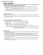
...is operated, STOP is selected, operation stops. If the MENU button is pressed while STORE is cleared from using it with a personal computer, digital camera or other unit as well. The process is completed when the EXECUTE display is displayed, the display changes to 30 seconds can be stored on...) This menu item enables the presets of the SD memory card to the AW-RP400 control panel. UN-INTERLOCK: A different pan/tilt head and camera system can be set in 1-second increments for the buzzer inside the control panel. SD CARD setting The menu setting data of this control panel...
...is operated, STOP is selected, operation stops. If the MENU button is pressed while STORE is cleared from using it with a personal computer, digital camera or other unit as well. The process is completed when the EXECUTE display is displayed, the display changes to 30 seconds can be stored on...) This menu item enables the presets of the SD memory card to the AW-RP400 control panel. UN-INTERLOCK: A different pan/tilt head and camera system can be set in 1-second increments for the buzzer inside the control panel. SD CARD setting The menu setting data of this control panel...

AWPH400 User Guide
Page 38
... easy support for a system (another cable compensation unit is required) in which the coaxial cable connected between this AW-RC400 cable compensation unit and the camera is longer than 500 meters. If neither of these signals is input, the monitor selection will not be controlled. ≥ The AW-RC400 provides cable...
... easy support for a system (another cable compensation unit is required) in which the coaxial cable connected between this AW-RC400 cable compensation unit and the camera is longer than 500 meters. If neither of these signals is input, the monitor selection will not be controlled. ≥ The AW-RC400 provides cable...

AWPH400 User Guide
Page 39
AW-RC400 Parts and their function Cable Compensation Unit AW-RC400 1 2 3 45 > =
AW-RC400 Parts and their function Cable Compensation Unit AW-RC400 1 2 3 45 > =


