
AWPH400 User Guide
Page 3
... safety information. Keep the small memory cards such as power-supply cord or plug is required when the apparatus has been damaged in any way, such as the SD Memory Card out of reach of children. Safety precautions IMPORTANT SAFETY INSTRUCTIONS Read these instructions. 3) Heed all warnings. 10) Protect the power cord form being walked on the unit and the applicable safety instructions listed...
... safety information. Keep the small memory cards such as power-supply cord or plug is required when the apparatus has been damaged in any way, such as the SD Memory Card out of reach of children. Safety precautions IMPORTANT SAFETY INSTRUCTIONS Read these instructions. 3) Heed all warnings. 10) Protect the power cord form being walked on the unit and the applicable safety instructions listed...
AWPH400 User Guide
Page 4
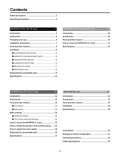
... precautions 2 Operating precautions 5 AW-PH400 Indoor Pan/Tilt Head 6 Introduction 6 Accessories 6 Precautions for use 6 Installation precautions 7 Parts and their function 8 Installation 12 $ Assembling the pan/tilt head 12 $ Setting the mounting direction switch 14 $ Setting the PCB switches 15 $ Installing the pan/tilt head 16 $ Mounting the camera 17 $ Attaching the wire 18 Replacing the consumable parts 19 Specifications 20 AW-RC400 Cable Compensation Unit 38 Introduction 38 Accessories 38 Parts and their...
... precautions 2 Operating precautions 5 AW-PH400 Indoor Pan/Tilt Head 6 Introduction 6 Accessories 6 Precautions for use 6 Installation precautions 7 Parts and their function 8 Installation 12 $ Assembling the pan/tilt head 12 $ Setting the mounting direction switch 14 $ Setting the PCB switches 15 $ Installing the pan/tilt head 16 $ Mounting the camera 17 $ Attaching the wire 18 Replacing the consumable parts 19 Specifications 20 AW-RC400 Cable Compensation Unit 38 Introduction 38 Accessories 38 Parts and their...
AWPH400 User Guide
Page 6
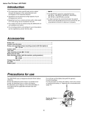
... regulations. Replace the lithium battery here. 6 Before discarding the pan/tilt head or its printed circuit boards, be performed at the end of its service life, ask a specialized contractor to dispose of 17.6 lbs (8 kg) can be rotated using the AW-RL400 roll unit available as an option. ≥ The shooting positions and settings for tally 1 Wire mounting screws...
... regulations. Replace the lithium battery here. 6 Before discarding the pan/tilt head or its printed circuit boards, be performed at the end of its service life, ask a specialized contractor to dispose of 17.6 lbs (8 kg) can be rotated using the AW-RL400 roll unit available as an option. ≥ The shooting positions and settings for tally 1 Wire mounting screws...
AWPH400 User Guide
Page 10
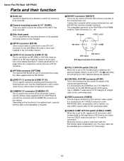
... the functions of the cables described in "Cable specifications" on the AW-PB504 SDI card or other card installed in the convertible camera. When it has been mounted. ? G CONTROL IN IP/RP connector [IP/RP] This is set to OFF, the (6) tally lamp will not light even if the selected signals are supplied. H VIDEO connector [VIDEO] This the output connector for the connecting cable. When this switch is used to control the zooming and...
... the functions of the cables described in "Cable specifications" on the AW-PB504 SDI card or other card installed in the convertible camera. When it has been mounted. ? G CONTROL IN IP/RP connector [IP/RP] This is set to OFF, the (6) tally lamp will not light even if the selected signals are supplied. H VIDEO connector [VIDEO] This the output connector for the connecting cable. When this switch is used to control the zooming and...

AWPH400 User Guide
Page 14
... dealer to install the unit.) $ Setting the mounting direction switch Set the switch as follows when the unit is to be installed on the ceiling. (This switch was set to the stand-alone installation position at the factory.) 1 Remove the four screws, and gently remove the pedestal connector panel. 2 Set switch S1 on the ceiling S1 Pedestal connector panel ≥ Be absolutely sure to turn off the power before changing the...
... dealer to install the unit.) $ Setting the mounting direction switch Set the switch as follows when the unit is to be installed on the ceiling. (This switch was set to the stand-alone installation position at the factory.) 1 Remove the four screws, and gently remove the pedestal connector panel. 2 Set switch S1 on the ceiling S1 Pedestal connector panel ≥ Be absolutely sure to turn off the power before changing the...
AWPH400 User Guide
Page 15
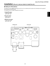
AW-PH400 Indoor Pan/Tilt Head AW-PH400 Installation (Be sure to ask your dealer to install the unit.) $ Setting the PCB switches The switches on the CONNECTOR PCB will need to be set in accordance with the signals to be transmitted and the equipment to be connected to the pan/tilt head. (The switches are set to support analog/SDI at the factory.) ≥ Analog/SDI support IP/IEEE switch: IEEE 422/IP switch: 422 ≥ Web card support IP/IEEE switch: IP 422/IP switch: IP ≥ IEEE1394 card support IP/IEEE switch: IEEE 422/IP switch: 422 IP/IEEE switch 422/IP switch 15
AW-PH400 Indoor Pan/Tilt Head AW-PH400 Installation (Be sure to ask your dealer to install the unit.) $ Setting the PCB switches The switches on the CONNECTOR PCB will need to be set in accordance with the signals to be transmitted and the equipment to be connected to the pan/tilt head. (The switches are set to support analog/SDI at the factory.) ≥ Analog/SDI support IP/IEEE switch: IEEE 422/IP switch: 422 ≥ Web card support IP/IEEE switch: IP 422/IP switch: IP ≥ IEEE1394 card support IP/IEEE switch: IEEE 422/IP switch: 422 IP/IEEE switch 422/IP switch 15

AWPH400 User Guide
Page 19
... Head AW-PH400 $ Replacing the battery The battery has a service life of its memory. The unit stores the preset positions, limiters and other data in its service life, the data will be replaced at periodic intervals. 19 Pedestal connector panel $ Replacing the motor Replace the motor when it from underneath the part with the arrow. 4 After disengaging the part with a new one. (Battery used: CR2032 manganese dioxide...
... Head AW-PH400 $ Replacing the battery The battery has a service life of its memory. The unit stores the preset positions, limiters and other data in its service life, the data will be replaced at periodic intervals. 19 Pedestal connector panel $ Replacing the motor Replace the motor when it from underneath the part with the arrow. 4 After disengaging the part with a new one. (Battery used: CR2032 manganese dioxide...

AWPH400 User Guide
Page 20
... Specifications Supply voltage: AC 120 V, 60 Hz Power consumption: 145 W 1 indicates safety information. The tilt range is limited to 190 degrees by the initial setting of camera to restrictions depending on the cable and lens of the AW-RP400. Specifications are approximate. Genlock input: BNC Black burst or composite video signal Prompter input (PROMPTER IN): BNC Through output to PROMPTER connector Prompter output (PROMPTER OUT): D-SUB 15-pin Camera video output VIDEO...
... Specifications Supply voltage: AC 120 V, 60 Hz Power consumption: 145 W 1 indicates safety information. The tilt range is limited to 190 degrees by the initial setting of camera to restrictions depending on the cable and lens of the AW-RP400. Specifications are approximate. Genlock input: BNC Black burst or composite video signal Prompter input (PROMPTER IN): BNC Through output to PROMPTER connector Prompter output (PROMPTER OUT): D-SUB 15-pin Camera video output VIDEO...
AWPH400 User Guide
Page 22
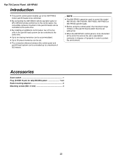
... same time. ≥ Up to ten tracing memories can be accommodated. ≥ Up to 50 preset memories can be set Rack-mounting adaptors 2 Mounting screws (M4!8 mm 4 22 Accessories Zoom switch 1 Plug (D-SUB 15-pin) for tally/INCOM system 1 set . ≥ The connection distance between the control panel and pan/tilt head system can be controlled at the end of its service life...
... same time. ≥ Up to ten tracing memories can be accommodated. ≥ Up to 50 preset memories can be set Rack-mounting adaptors 2 Mounting screws (M4!8 mm 4 22 Accessories Zoom switch 1 Plug (D-SUB 15-pin) for tally/INCOM system 1 set . ≥ The connection distance between the control panel and pan/tilt head system can be controlled at the end of its service life...

AWPH400 User Guide
Page 23
... sounds, and the CALL button lamp lights. 23 Remember to set the OPERATE switch on the slave control panel to [ON] first before setting the OPERATE switch on the master control panel to [ON]. 4 INCOM jack The INCOM (inter-communication) headset is connected here. 5 LEVEL control Use this to adjust the volume of the headset's receiver. 6 CALL button When this switch is set to [ON], the power supply from the connected pan/tilt heads to the cameras...
... sounds, and the CALL button lamp lights. 23 Remember to set the OPERATE switch on the slave control panel to [ON] first before setting the OPERATE switch on the master control panel to [ON]. 4 INCOM jack The INCOM (inter-communication) headset is connected here. 5 LEVEL control Use this to adjust the volume of the headset's receiver. 6 CALL button When this switch is set to [ON], the power supply from the connected pan/tilt heads to the cameras...

AWPH400 User Guide
Page 24
.... Adjust the iris using the IRIS [AUTO/MAN] button on the control panel does not work when the WV-CB700A remote control box is tilted; PAN POSITION indicator Sixteen LEDs are used to MANU. The iris is opened by turning the dial clockwise and stopped down by turning it is pressed, the setting is adjusted manually using the FOCUS dial on its left by the direction...
.... Adjust the iris using the IRIS [AUTO/MAN] button on the control panel does not work when the WV-CB700A remote control box is tilted; PAN POSITION indicator Sixteen LEDs are used to MANU. The iris is opened by turning the dial clockwise and stopped down by turning it is pressed, the setting is adjusted manually using the FOCUS dial on its left by the direction...

AWPH400 User Guide
Page 25
... numbers of the AW-CB400 remote operation panel, if this panel is connected to the pan/tilt control panel, the lamps with the numbers corresponding to those connectors light up or down, they will go in that PRESET MEMORY selection button. J TRACING MEMORY [START POINT, START, STOP, RESTORE, RESET, 1 to 10] buttons Use these buttons to call the settings registered in the tracing memories, the recording/play time displays...
... numbers of the AW-CB400 remote operation panel, if this panel is connected to the pan/tilt control panel, the lamps with the numbers corresponding to those connectors light up or down, they will go in that PRESET MEMORY selection button. J TRACING MEMORY [START POINT, START, STOP, RESTORE, RESET, 1 to 10] buttons Use these buttons to call the settings registered in the tracing memories, the recording/play time displays...

AWPH400 User Guide
Page 26
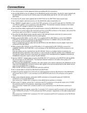
... is connected, the cameras cannot be controlled from the AW-CB400 remote operation panel even if the AW-CB400 is set to the GND level, the TALLY lamp on the video switcher or other unit. When the TALLY input connector is connected. Pan/Tilt Control Panel AW-RP400 Parts and their function $ Rear panel N M O P Q R M EXT CONT IN/OUT connectors When an additional AW-RP400 control panel...
... is connected, the cameras cannot be controlled from the AW-CB400 remote operation panel even if the AW-CB400 is set to the GND level, the TALLY lamp on the video switcher or other unit. When the TALLY input connector is connected. Pan/Tilt Control Panel AW-RP400 Parts and their function $ Rear panel N M O P Q R M EXT CONT IN/OUT connectors When an additional AW-RP400 control panel...

AWPH400 User Guide
Page 28
... another menu item to select a menu item. 3 When the CONT dial is pressed, what has been set appears on the bottom line. Pan/Tilt Control Panel AW-RP400 Menu settings $ Operation method 1 The menu setting items are switched each time the dial is pressed. 4 When a setting is displayed, the setting can be selected. 6 To exit the setting menu, hold down for two or more seconds. DIRECTION PAN...
... another menu item to select a menu item. 3 When the CONT dial is pressed, what has been set appears on the bottom line. Pan/Tilt Control Panel AW-RP400 Menu settings $ Operation method 1 The menu setting items are switched each time the dial is pressed. 4 When a setting is displayed, the setting can be selected. 6 To exit the setting menu, hold down for two or more seconds. DIRECTION PAN...

AWPH400 User Guide
Page 29
...performed using the master AW-RP400 control panel. 29 PRIORITY (MASTER/SLAVE) When two AW-RP400 pan/tilt control panels have been ceded to the other control panel. This setting is selected, the slave AW-RP400 has priority. AW-RP400 Menu settings $ List of the CONTROL SELECT buttons is selected as the setting...RP400 control panel with a low priority, the CONTROL SELECT button lamps on the AW-RP400 control panel with the low priority start flashing to indicate that the control rights have been connected, the priority of menu items and settings Menu item PRIORITY DIRECTION TILT RANGE ...
...performed using the master AW-RP400 control panel. 29 PRIORITY (MASTER/SLAVE) When two AW-RP400 pan/tilt control panels have been ceded to the other control panel. This setting is selected, the slave AW-RP400 has priority. AW-RP400 Menu settings $ List of the CONTROL SELECT buttons is selected as the setting...RP400 control panel with a low priority, the CONTROL SELECT button lamps on the AW-RP400 control panel with the low priority start flashing to indicate that the control rights have been connected, the priority of menu items and settings Menu item PRIORITY DIRECTION TILT RANGE ...
AWPH400 User Guide
Page 32
... screen. If the MENU button is pressed while STORE is displayed, the display changes to 30s): This sets the stop time. AUTO RUN setting (START No., END No., INTERVAL) This menu item enables the presets of the preset to OFF while EXECUTE is displayed. ≥ The tracing memory data is not stored. 32 UN-INTERLOCK: A different pan/tilt head and camera system can be set the OPERATE switch...
... screen. If the MENU button is pressed while STORE is displayed, the display changes to 30s): This sets the stop time. AUTO RUN setting (START No., END No., INTERVAL) This menu item enables the presets of the preset to OFF while EXECUTE is displayed. ≥ The tracing memory data is not stored. 32 UN-INTERLOCK: A different pan/tilt head and camera system can be set the OPERATE switch...

AWPH400 User Guide
Page 37
... AW-RP400 Supply voltage: DC 12.0 V Power consumption: Approx. 13 W 1 indicates safety information. Input connectors DC 12V IN: CONTROL IN FROM ROP: CONTROL IN FROM RCB: EXT CONT IN: REMOTE: XLR, 4 pins D-SUB 29-pin, cable supplied with AW-CB400 remote operation panel 10-pin round connector, cable supplied with WV-CB700A RJ45, additional AW-RP400 control signal input; 10BASE-T straight cable (UTP category 5), max. 500 meters 50-pin D-SUB connector, external control input, AW-CA50T9 Output connectors CONTROL OUT TO...
... AW-RP400 Supply voltage: DC 12.0 V Power consumption: Approx. 13 W 1 indicates safety information. Input connectors DC 12V IN: CONTROL IN FROM ROP: CONTROL IN FROM RCB: EXT CONT IN: REMOTE: XLR, 4 pins D-SUB 29-pin, cable supplied with AW-CB400 remote operation panel 10-pin round connector, cable supplied with WV-CB700A RJ45, additional AW-RP400 control signal input; 10BASE-T straight cable (UTP category 5), max. 500 meters 50-pin D-SUB connector, external control input, AW-CA50T9 Output connectors CONTROL OUT TO...

AWPH400 User Guide
Page 39
AW-RC400 Parts and their function Cable Compensation Unit AW-RC400 1 2 3 45 > =
AW-RC400 Parts and their function Cable Compensation Unit AW-RC400 1 2 3 45 > =
AWPH400 User Guide
Page 49
... be output from the MONITOR1 connector and the video signals of the camera selected by the AW-CB400 can be controlled from the AW-CB400. When the WV-CB700A is a multiple number of cameras, one camera can be controlled from the WV-CB700A. Power is 50 meters when using UTP category 5 cables or their equivalent. ≥ Use the camera cables supplied with the pan/tilt head to connect the...
... be output from the MONITOR1 connector and the video signals of the camera selected by the AW-CB400 can be controlled from the AW-CB400. When the WV-CB700A is a multiple number of cameras, one camera can be controlled from the WV-CB700A. Power is 50 meters when using UTP category 5 cables or their equivalent. ≥ Use the camera cables supplied with the pan/tilt head to connect the...

AWPH400 User Guide
Page 55
... registered. The lamp of the START button stops flashing, and the lamp of the button pressed now lights, and START button flashes. Operating procedures 3 Press the START POINT button. Playing the tracing memory data 1 Select the pan/tilt head system using the CONTROL SELECT button, and proceed with numbers exceeding the number of the button in which the data is operated. ≥ The buzzer sounds when tracing memory play of the...
... registered. The lamp of the START button stops flashing, and the lamp of the button pressed now lights, and START button flashes. Operating procedures 3 Press the START POINT button. Playing the tracing memory data 1 Select the pan/tilt head system using the CONTROL SELECT button, and proceed with numbers exceeding the number of the button in which the data is operated. ≥ The buzzer sounds when tracing memory play of the...


