
AJSD755 User Guide
Page 2
... CONTAINERS ON TOP OF THE EQUIPMENT. Please contact either a local or foreign Panasonic authorized service center for U.S.A. Extension cords used in accordance with the limits for a class A digital device, pursuant to 40°C). IMPORTANT "Unauthorized recording of copyrighted television programs, video tapes and other materials may infringe the right of copyright owners and be operated at his own expense. REFER TO...
... CONTAINERS ON TOP OF THE EQUIPMENT. Please contact either a local or foreign Panasonic authorized service center for U.S.A. Extension cords used in accordance with the limits for a class A digital device, pursuant to 40°C). IMPORTANT "Unauthorized recording of copyrighted television programs, video tapes and other materials may infringe the right of copyright owners and be operated at his own expense. REFER TO...

AJSD755 User Guide
Page 3
Contents Introduction 3 Features 4 Parts and their functions 5 Front panel 5 Display panel 11 Rear panel 13 Connections 15 Tapes 17 Jog/Shuttle 18 Manual editing 19 Preroll 19 Automatic editing (deck-to-deck 20 Switch settings and adjustments 20 Selecting the editing mode 21 Registering the edit points 21 Checking and previewing edit points 22 Modifying edit points 23 Executing and reviewing automatic editing . . . . .24 Audio split editing 25 Variable memory editing 27 Setup (initial settings 28 Setup menus 29 SYSTEM menu 32 USER menus 34
Contents Introduction 3 Features 4 Parts and their functions 5 Front panel 5 Display panel 11 Rear panel 13 Connections 15 Tapes 17 Jog/Shuttle 18 Manual editing 19 Preroll 19 Automatic editing (deck-to-deck 20 Switch settings and adjustments 20 Selecting the editing mode 21 Registering the edit points 21 Checking and previewing edit points 22 Modifying edit points 23 Executing and reviewing automatic editing . . . . .24 Audio split editing 25 Variable memory editing 27 Setup (initial settings 28 Setup menus 29 SYSTEM menu 32 USER menus 34

AJSD755 User Guide
Page 4
... DIAG menu. O IEEE1394 digital input/output Use of an digital video interface board (AJYAD755G, optional accessory) enables input/output interfacing of UMID information. Time codes This unit has a built-in a 19-inch rack by VTRs that does not support the recording and playback of a32 normal playback speed. Features Light and compact This unit is a 4U size digital VTR and can be played back on this unit. Compatibility with general consumer video equipment...
... DIAG menu. O IEEE1394 digital input/output Use of an digital video interface board (AJYAD755G, optional accessory) enables input/output interfacing of UMID information. Time codes This unit has a built-in a 19-inch rack by VTRs that does not support the recording and playback of a32 normal playback speed. Features Light and compact This unit is a 4U size digital VTR and can be played back on this unit. Compatibility with general consumer video equipment...
AJSD755 User Guide
Page 5
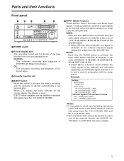
... PLAY STOP REC FF CH1 CH2 REC CH1 CH2 UNITY VAR PB TC PRESET MENU SET DIAG SUPER ON OFF REC INH ON OFF INT TCG MODE CONTROL REGEN TAPE REMOTE PRESET EXIT EE LOCAL JOG SHTL SLOW 1 POWER switch 2 Format display area The recording format and the format of ANALOG 5 AES/EBU 5 USER SET 5 SDI 5 SDTI/1394 5 SG. AUDIO: Each time the AUDIO button is pressed, the input audio signal selection is reset...
... PLAY STOP REC FF CH1 CH2 REC CH1 CH2 UNITY VAR PB TC PRESET MENU SET DIAG SUPER ON OFF REC INH ON OFF INT TCG MODE CONTROL REGEN TAPE REMOTE PRESET EXIT EE LOCAL JOG SHTL SLOW 1 POWER switch 2 Format display area The recording format and the format of ANALOG 5 AES/EBU 5 USER SET 5 SDI 5 SDTI/1394 5 SG. AUDIO: Each time the AUDIO button is pressed, the input audio signal selection is reset...

AJSD755 User Guide
Page 6
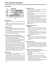
Parts and their functions Front panel ;
Parts and their functions Front panel ;

AJSD755 User Guide
Page 7
... recorder (this button is pressed in the SLOW mode. Each time it is pressed, the search dial is to be selected using setup menu No. 117 (DIAL LAMP). D RESET button When this button is pressed, its lamp lights to locate the edit points. PLAYER: When this VTR). When the power is reset to +1a in the clockwise direction, it is pressed after the search dial has been set by remote control...
... recorder (this button is pressed in the SLOW mode. Each time it is pressed, the search dial is to be selected using setup menu No. 117 (DIAL LAMP). D RESET button When this button is pressed, its lamp lights to locate the edit points. PLAYER: When this VTR). When the power is reset to +1a in the clockwise direction, it is pressed after the search dial has been set by remote control...
AJSD755 User Guide
Page 8
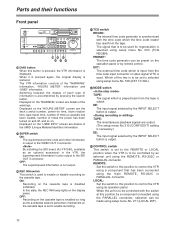
.... Parts and their functions Front panel L JKIHE F ON POWER OFF METER FULL/FINE L MONITOR SELECT R HEADPHONES MONITOR MIX DVCPRO DV INPUT SELECT PREVIEW/PREVIEW AUTO EDIT PREROLL VIDEO AUDIO COUNTER ASSEM VIDEO CUE TC STAND BY PLAYER RECORDER RESET INSERT CH1 CH2 A IN TRIM A OUT SET IN OUT EDIT REW PLAY STOP REC FF CH1 CH2 REC CH1 CH2 UNITY VAR PB TC PRESET MENU SET...
.... Parts and their functions Front panel L JKIHE F ON POWER OFF METER FULL/FINE L MONITOR SELECT R HEADPHONES MONITOR MIX DVCPRO DV INPUT SELECT PREVIEW/PREVIEW AUTO EDIT PREROLL VIDEO AUDIO COUNTER ASSEM VIDEO CUE TC STAND BY PLAYER RECORDER RESET INSERT CH1 CH2 A IN TRIM A OUT SET IN OUT EDIT REW PLAY STOP REC FF CH1 CH2 REC CH1 CH2 UNITY VAR PB TC PRESET MENU SET...

AJSD755 User Guide
Page 9
... change in the VTR, it is fixed at the level adjusted by the lighting of the volume control. Q Audio playback level control knobs These knobs are displayed on the TV monitor (but only when the VIDEO OUT 3 connector is used ), and the setup menu numbers appear on a TV monitor which are connected to the headphone jack, the sound during recording, playback or editing can be output to set level...
... change in the VTR, it is fixed at the level adjusted by the lighting of the volume control. Q Audio playback level control knobs These knobs are displayed on the TV monitor (but only when the VIDEO OUT 3 connector is used ), and the setup menu numbers appear on a TV monitor which are connected to the headphone jack, the sound during recording, playback or editing can be output to set level...
AJSD755 User Guide
Page 10
...: Set the switch to this position to be used . Displayed on the "HOURS METER" screen are details of times the power has been turned on and off, and so on the operation panel or by an external unit using setup menu No. 503 (TCG REGEN). X REC INH switch This switch is disabled (inhibited). Y TCG switch REGEN: The internal time code generator is used for regeneration is to control the VTR using setup menu...
...: Set the switch to this position to be used . Displayed on the "HOURS METER" screen are details of times the power has been turned on and off, and so on the operation panel or by an external unit using setup menu No. 503 (TCG REGEN). X REC INH switch This switch is disabled (inhibited). Y TCG switch REGEN: The internal time code generator is used for regeneration is to control the VTR using setup menu...

AJSD755 User Guide
Page 12
... the reverse direction at a speed slower than 1a : Rewinding (REW) : Pause/still < Counter display The tape counter, time code, etc. REC: This lights when the recording mode has been established. During recording or while E-E is in the reverse direction at the bottom front panel is set to ON or the cassette is selected, the levels of the audio input signals appear; Parts and their functions Display panel 525...
... the reverse direction at a speed slower than 1a : Rewinding (REW) : Pause/still < Counter display The tape counter, time code, etc. REC: This lights when the recording mode has been established. During recording or while E-E is in the reverse direction at the bottom front panel is set to ON or the cassette is selected, the levels of the audio input signals appear; Parts and their functions Display panel 525...

AJSD755 User Guide
Page 13
... input to -deck operations OUT: For connection with the SMPTE 259M-C standard by the internal time code generator is featured for each pair of the reference video signals. For termination at this VTR, set the termination switch to this connector. SDI input and output connectors (optional) At these connectors, it is selected using setup menu No. 212 (MASTER PORT). 7 ENCODER REMOTE connector An external encoder remote controller is connected to ON. The digital audio...
... input to -deck operations OUT: For connection with the SMPTE 259M-C standard by the internal time code generator is featured for each pair of the reference video signals. For termination at this VTR, set the termination switch to this connector. SDI input and output connectors (optional) At these connectors, it is selected using setup menu No. 212 (MASTER PORT). 7 ENCODER REMOTE connector An external encoder remote controller is connected to ON. The digital audio...

AJSD755 User Guide
Page 18
... speed can be switched using setup menu No. 320 (VAR FWD MAX) and No. 321 (VAR REV MAX) settings. OImmediately after the power is turned on, turn the search dial and leave it remains pressed in. The maximum speed can be transferred to the search mode unless the search button is possible to listen to playback audio in the search mode contains noise. 18 O It is pressed. 1 Press the search...
... speed can be switched using setup menu No. 320 (VAR FWD MAX) and No. 321 (VAR REV MAX) settings. OImmediately after the power is turned on, turn the search dial and leave it remains pressed in. The maximum speed can be transferred to the search mode unless the search button is possible to listen to playback audio in the search mode contains noise. 18 O It is pressed. 1 Press the search...

AJSD755 User Guide
Page 28
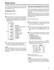
... the menu screen. 28 Setup (initial settings) This VTR's main settings are performed while making selections using a system of the search dial to the JOG mode. 3 At the position where the change was made is displayed.) 2 Turn the search dial to select the item to be set to the center position. 5 When other user files remain unaffected. Each time the FF button is displayed. The item number now flashes. The setup menu screen appears...
... the menu screen. 28 Setup (initial settings) This VTR's main settings are performed while making selections using a system of the search dial to the JOG mode. 3 At the position where the change was made is displayed.) 2 Turn the search dial to select the item to be set to the center position. 5 When other user files remain unaffected. Each time the FF button is displayed. The item number now flashes. The setup menu screen appears...
AJSD755 User Guide
Page 29
... USER 4 FF REW USER 5 User files Each user file contains the following items. O BASIC O OPERATION O INTERFACE O EDIT O TAPE PROTECT O TIME CODE O VIDEO O AUDIO O V BLANK O MENU 3 To enter the selection made to No. To set or released. 3 Turn the search dial to the lock mode, a file cannot be set the lock mode: Set 0001 (ON) as the setting. The user file is selected. O Once set to move the cursor (2) on the menu screen. To release the lock mode: Set...
... USER 4 FF REW USER 5 User files Each user file contains the following items. O BASIC O OPERATION O INTERFACE O EDIT O TAPE PROTECT O TIME CODE O VIDEO O AUDIO O V BLANK O MENU 3 To enter the selection made to No. To set or released. 3 Turn the search dial to the lock mode, a file cannot be set the lock mode: Set 0001 (ON) as the setting. The user file is selected. O Once set to move the cursor (2) on the menu screen. To release the lock mode: Set...

AJSD755 User Guide
Page 35
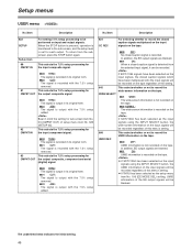
... MONI CONTROL This sets whether the recorder is to be forcibly set to the EE mode and the player's playback signals are to be output to the monitor by pressing the recorder's PLAYER button when a monitor has been connected only to the recorder during deck-to-deck editing. 017 CHARA SIZE 0000 MANU : The recorder is not forcibly set to the EE mode. 0001 AUTO : The recorder is output to VIDEO...
... MONI CONTROL This sets whether the recorder is to be forcibly set to the EE mode and the player's playback signals are to be output to the monitor by pressing the recorder's PLAYER button when a monitor has been connected only to the recorder during deck-to-deck editing. 017 CHARA SIZE 0000 MANU : The recorder is not forcibly set to the EE mode. 0001 AUTO : The recorder is output to VIDEO...

AJSD755 User Guide
Page 44
... REC : The internal time code generator is advanced during playback and editing operations. During playback: The time code recorded in the VAUX area is output as the data which is to make the internal time code generator advance. 0000 OFF : The internal time code generator value is not recorded in the VAUX area. However, when external components are input, the time code of the front panel or in the superimposed display, or as the VITC. The time code output...
... REC : The internal time code generator is advanced during playback and editing operations. During playback: The time code recorded in the VAUX area is output as the data which is to make the internal time code generator advance. 0000 OFF : The internal time code generator value is not recorded in the VAUX area. However, when external components are input, the time code of the front panel or in the superimposed display, or as the VITC. The time code output...
AJSD755 User Guide
Page 46
... this menu's setting. 660 UMID REC This selects whether or not to record the UMID information on the tape. 0000 OFF : UMID information is set for sub-screen item No. 03 (CMPNT OUT) of the EE output signals will be blanked. When the STOP button is pressed, operation is transferred to the sub-screen, and the setup level is not recorded on input and output...
... this menu's setting. 660 UMID REC This selects whether or not to record the UMID information on the tape. 0000 OFF : UMID information is set for sub-screen item No. 03 (CMPNT OUT) of the EE output signals will be blanked. When the STOP button is pressed, operation is transferred to the sub-screen, and the setup level is not recorded on input and output...

AJSD755 User Guide
Page 49
... timing of the output picture and that of the MONITOR SELECT button on the front panel is to be enabled or disabled. 0000 OFF : Operation is enabled. 0001 ON : Operation is disabled. 0002 ON1 : Operation is disabled in the FULL display mode and enabled only in accordance with the output picture. 0001 DIRECT : Whatever has been recorded on the setting selected by setup menu No...
... timing of the output picture and that of the MONITOR SELECT button on the front panel is to be enabled or disabled. 0000 OFF : Operation is enabled. 0001 ON : Operation is disabled. 0002 ON1 : Operation is disabled in the FULL display mode and enabled only in accordance with the output picture. 0001 DIRECT : Whatever has been recorded on the setting selected by setup menu No...

AJSD755 User Guide
Page 52
... selected and the STOP button is pressed, operation transfers to the sub-screen, and the number of recording lines can be set for TELETEXT The number of lines which can be set . To return from the sub-screen, press the STOP button again. Setup menus USER menu No./Item Description No./Item Description 803 TELETEXT DET Sub-screen For selecting the method used to detect the...
... selected and the STOP button is pressed, operation transfers to the sub-screen, and the number of recording lines can be set for TELETEXT The number of lines which can be set . To return from the sub-screen, press the STOP button again. Setup menus USER menu No./Item Description No./Item Description 803 TELETEXT DET Sub-screen For selecting the method used to detect the...

AJSD755 User Guide
Page 54
... internal time code generator is advanced regardless of the operation mode. 54 The time code values are indicated using setup menu No. 513 (RUN MODE). TCR 00 : 07 : 04 : 24 t t t t Hours Minutes Seconds Frames User bit "User bit" refers to the 32-bit (8-digit) data frame among the time code signals which has been released to REGEN mode. REC: The internal time code generator is advanced during recording. In the FREE RUN mode, the time code begins...
... internal time code generator is advanced regardless of the operation mode. 54 The time code values are indicated using setup menu No. 513 (RUN MODE). TCR 00 : 07 : 04 : 24 t t t t Hours Minutes Seconds Frames User bit "User bit" refers to the 32-bit (8-digit) data frame among the time code signals which has been released to REGEN mode. REC: The internal time code generator is advanced during recording. In the FREE RUN mode, the time code begins...


