

AJHPX3000G User Guide
Page 9
... playback instantly. This facilitates continuous recording. It is also possible to select DVCPRO HD in addition to free space. _ HD: Format AVC-I100/AVC-I50/DVCPRO HD SD: Format DVCPRO50 Recorded video is compressed through a component digital recording method that uses a state-of-the-art compression technology, and sound is recorded using the non-compression PCM recording method, which excels in HD mode. z Thumbnail display on the LCD monitor The 3.5-inch color LCD...
... playback instantly. This facilitates continuous recording. It is also possible to select DVCPRO HD in addition to free space. _ HD: Format AVC-I100/AVC-I50/DVCPRO HD SD: Format DVCPRO50 Recorded video is compressed through a component digital recording method that uses a state-of-the-art compression technology, and sound is recorded using the non-compression PCM recording method, which excels in HD mode. z Thumbnail display on the LCD monitor The 3.5-inch color LCD...

AJHPX3000G User Guide
Page 11
... HD mode, the MON OUT output connector and the VIDEO OUT connector (in AJ-HPX3000 can be used for confirming shot images on the SD monitor. (Refer to page 44) _ HD/SD SDI input function (when the AJYA350AG is also possible to store data on a P2 card onto a USB 2.0-connected external hard disk equipped with the AJ-YA350AG extension board attached can record SDI signals input through the IEEE1394 digital...
... HD mode, the MON OUT output connector and the VIDEO OUT connector (in AJ-HPX3000 can be used for confirming shot images on the SD monitor. (Refer to page 44) _ HD/SD SDI input function (when the AJYA350AG is also possible to store data on a P2 card onto a USB 2.0-connected external hard disk equipped with the AJ-YA350AG extension board attached can record SDI signals input through the IEEE1394 digital...
AJHPX3000G User Guide
Page 24
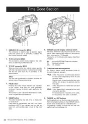
... camera-recorder. 4. UB: TC: CTL: User bits/DATE/TIME/Time zone indicated. R-RUN: Select this switch and the 7.TCG switch. F-RUN: Select this button freezes the time data indication on the positions of the display window depend on the counter. This function is the SET button. Pressing the 4.HOLD button also displays Date/Time/ Time Zone. Note that of an external device this must be input in the same format as the system mode of a particular recorded...
... camera-recorder. 4. UB: TC: CTL: User bits/DATE/TIME/Time zone indicated. R-RUN: Select this switch and the 7.TCG switch. F-RUN: Select this button freezes the time data indication on the positions of the display window depend on the counter. This function is the SET button. Pressing the 4.HOLD button also displays Date/Time/ Time Zone. Note that of an external device this must be input in the same format as the system mode of a particular recorded...

AJHPX3000G User Guide
Page 36
... in the USER SW screen, which data may not be undefined. z The internal memory does not store video or sound when a playback or recording review is set from the CAM OPERATION page. To use this reason, no video or sound can be found in internal memory will not be set to OFF. The storage duration of video and sound data coming from the camera. z Immediately after the power is turned on, the menu option PRE REC TIME is...
... in the USER SW screen, which data may not be undefined. z The internal memory does not store video or sound when a playback or recording review is set from the CAM OPERATION page. To use this reason, no video or sound can be found in internal memory will not be set to OFF. The storage duration of video and sound data coming from the camera. z Immediately after the power is turned on, the menu option PRE REC TIME is...

AJHPX3000G User Guide
Page 37
... Content recorded B Card3 C Recording Cycle 2 D B C Data are the options for the menu option INTERVAL REC MODE. ON: Interval recording performed. When the 1394 CONTROL is set to "ON" The option LOOP REC MODE can be found in order. Interval Recording It is removed, LOOP REC stops. To use this option, open the REC FUNCTION screen from the SYSTEM SETTING page, and set to ON, the P2 card remaining free space indicates the minimum guaranteed recording time. z During recording...
... Content recorded B Card3 C Recording Cycle 2 D B C Data are the options for the menu option INTERVAL REC MODE. ON: Interval recording performed. When the 1394 CONTROL is set to "ON" The option LOOP REC MODE can be found in order. Interval Recording It is removed, LOOP REC stops. To use this option, open the REC FUNCTION screen from the SYSTEM SETTING page, and set to ON, the P2 card remaining free space indicates the minimum guaranteed recording time. z During recording...

AJHPX3000G User Guide
Page 38
... STOP button REC TIME (Recording time=t) To check the previous recording during a pause. The video and sound stored in memory are generated as that in the display when the internal recording mode is selected. Interval recording starts. To divide clips or to change even if the POWER switch is turned OFF. 38 Recording and PlaybackɿInterval Recording Recording stops. Then, the camera accesses the P2 card to record the video stored in memory before recording starts. Shooting procedures when INTERVAL REC is ON 1 Following basic operations...
... STOP button REC TIME (Recording time=t) To check the previous recording during a pause. The video and sound stored in memory are generated as that in the display when the internal recording mode is selected. Interval recording starts. To divide clips or to change even if the POWER switch is turned OFF. 38 Recording and PlaybackɿInterval Recording Recording stops. Then, the camera accesses the P2 card to record the video stored in memory before recording starts. Shooting procedures when INTERVAL REC is ON 1 Following basic operations...
AJHPX3000G User Guide
Page 39
... the P2 card. z Operation mode INTERVAL REC does not work during this function does not work when the recording signals are disabled. z If the power is turned off during recording If the AJ-HPX3000 is turned off . z To start emergency recording during a pause By setting the REC button to USER MAIN or USER1/ USER2, emergency recording can be operated during interval recording. Press the STOP button before operating thumbnails. z Removing cards During INTERVAL REC mode operation, the P2 card access LED for the inserted P2 card blinks...
... the P2 card. z Operation mode INTERVAL REC does not work during this function does not work when the recording signals are disabled. z If the power is turned off during recording If the AJ-HPX3000 is turned off . z To start emergency recording during a pause By setting the REC button to USER MAIN or USER1/ USER2, emergency recording can be operated during interval recording. Press the STOP button before operating thumbnails. z Removing cards During INTERVAL REC mode operation, the P2 card access LED for the inserted P2 card blinks...

AJHPX3000G User Guide
Page 43
... each setting, see [Connection through the REC SIGNAL menu option, you to record video. The native recording format applies to the SYSTEM MODE option, the viewfinder indicates "TURN POWER OFF." Adjustments and Settings for Recording Video system and Recording format The unit uses an interlace/progressive scan (reading all pixels) switchable type CCD. The CAMERA MODE option allows you can record external input signals such as 1394 and SDI (optional). REC MODE menu option Used to select the recording mode For HD mode...
... each setting, see [Connection through the REC SIGNAL menu option, you to record video. The native recording format applies to the SYSTEM MODE option, the viewfinder indicates "TURN POWER OFF." Adjustments and Settings for Recording Video system and Recording format The unit uses an interlace/progressive scan (reading all pixels) switchable type CCD. The CAMERA MODE option allows you can record external input signals such as 1394 and SDI (optional). REC MODE menu option Used to select the recording mode For HD mode...

AJHPX3000G User Guide
Page 51
.... Note that the AUDIO IN switch can be used to compress the video level with high brightness, there are not available. Then, press the dial button to accept that allows the JOG dial button to change the input signal: later specification takes precedence. 51 Adjustments and Settings for backlight compensation. C.TEMPɿ The function to switch to which is highlighted and starts blinking, indicating that...
.... Note that the AUDIO IN switch can be used to compress the video level with high brightness, there are not available. Then, press the dial button to accept that allows the JOG dial button to change the input signal: later specification takes precedence. 51 Adjustments and Settings for backlight compensation. C.TEMPɿ The function to switch to which is highlighted and starts blinking, indicating that...

AJHPX3000G User Guide
Page 55
... of time data Time code The TCG switch can be used . Free run . However, in a clip on a P2 card. When the GPS unit AJ-GPS910G is installed, the built-in the VIDEO AUX area. Adjustments and Settings for Recording Setting Time Data AJ-HPX3000 supports time codes, user bits, date, and time (real time) data, which are recorded as data for PCs). Description of a clip that can be used to store the date and time while the power is fixed to the time code input...
... of time data Time code The TCG switch can be used . Free run . However, in a clip on a P2 card. When the GPS unit AJ-GPS910G is installed, the built-in the VIDEO AUX area. Adjustments and Settings for Recording Setting Time Data AJ-HPX3000 supports time codes, user bits, date, and time (real time) data, which are recorded as data for PCs). Description of a clip that can be used to store the date and time while the power is fixed to the time code input...

AJHPX3000G User Guide
Page 59
... Greenwich Mean Time in the display window. 9 Position the TCG switch at [SET]. 10 Use the # and $ buttons to set . ! When the GPS unit AJ-GPS910G is turned on a lithium battery built into the camera-recorder. Adjustments and Settings for Recording : Setting Time Data 59 Advances the blinking number by one digit. When the lithium battery is exhausted, the viewfinder indicates the message "BACKUP BATT EMPTY" when the power is turned off. The internal clock starts...
... Greenwich Mean Time in the display window. 9 Position the TCG switch at [SET]. 10 Use the # and $ buttons to set . ! When the GPS unit AJ-GPS910G is turned on a lithium battery built into the camera-recorder. Adjustments and Settings for Recording : Setting Time Data 59 Advances the blinking number by one digit. When the lithium battery is exhausted, the viewfinder indicates the message "BACKUP BATT EMPTY" when the power is turned off. The internal clock starts...

AJHPX3000G User Guide
Page 70
... displayed when the menu option REC STATUS of the P2 card slot that the battery level is fully charged. 70 Adjustments and Settings for example because the P2 card has no free space, the indication blinks. This indicates that contains the target card is set to "ONE CARD", the number of the VF INDICATOR3 is indicated, together with a user button. P2 card remaining free space (MODE CHECK) [1]¢¢¢min 7. Battery type, selected through the 1394 connection...
... displayed when the menu option REC STATUS of the P2 card slot that the battery level is fully charged. 70 Adjustments and Settings for example because the P2 card has no free space, the indication blinks. This indicates that contains the target card is set to "ONE CARD", the number of the VF INDICATOR3 is indicated, together with a user button. P2 card remaining free space (MODE CHECK) [1]¢¢¢min 7. Battery type, selected through the 1394 connection...

AJHPX3000G User Guide
Page 73
... during proxy recording, the message is displayed (when AJYAX800G is loaded, or the P2 card contains no free space. The RET button was pressed to the USB HOST mode. The P2 card is in USB DEVICE mode. No return video, playback, or externally input video can be output to or playing data from the wireless receiver is displayed when the recording starts or completes while a P2 card with an error code.For more information, see [Shot Mark Function] (page...
... during proxy recording, the message is displayed (when AJYAX800G is loaded, or the P2 card contains no free space. The RET button was pressed to the USB HOST mode. The P2 card is in USB DEVICE mode. No return video, playback, or externally input video can be output to or playing data from the wireless receiver is displayed when the recording starts or completes while a P2 card with an error code.For more information, see [Shot Mark Function] (page...
AJHPX3000G User Guide
Page 103
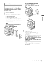
... the operating instructions unless you purchased the camera-recorder. PreparationɿPower Supply 103 Battery Case (for NP-1 type) When using the BATTERY SELECT item setting, select TYPE A or TYPE B, and set the items that contained in the direction of the battery. Select BATTERY SELECT from the screen on the camera- Please refer to pinch the connection cord. Select the battery type listed under BATTERY SELECT. When using another battery which cannot be selected using a V-mount type battery...
... the operating instructions unless you purchased the camera-recorder. PreparationɿPower Supply 103 Battery Case (for NP-1 type) When using the BATTERY SELECT item setting, select TYPE A or TYPE B, and set the items that contained in the direction of the battery. Select BATTERY SELECT from the screen on the camera- Please refer to pinch the connection cord. Select the battery type listed under BATTERY SELECT. When using another battery which cannot be selected using a V-mount type battery...

AJHPX3000G User Guide
Page 134
... condition where the camera-recorder thumbnail screen is used as the output signals of the connected devices ON and OFF or by the external device. 3 Through the REC TALLY menu option on the MAIN OPERATION page can be connected with a red tally LED. 4 Open on the SYSTEM SETTING page to set to FRM. Perform recording operation after the latest clip. Š Software must be output. When these video and audio signals are monitored...
... condition where the camera-recorder thumbnail screen is used as the output signals of the connected devices ON and OFF or by the external device. 3 Through the REC TALLY menu option on the MAIN OPERATION page can be connected with a red tally LED. 4 Open on the SYSTEM SETTING page to set to FRM. Perform recording operation after the latest clip. Š Software must be output. When these video and audio signals are monitored...

AJHPX3000G User Guide
Page 137
... remaining free space on a card-by-card basis. For more information, see [Switching to the USB HOST mode] (page 136). 2 Connect the hard disc drive to the camera-recorder via USB 2.0 with external devices using the USB 2.0 port 137 The screen provides the information about the hard disc drive. A drive formatted with the cursor button ($) to display the thumbnail screen. 4 Press the MENU button and select HDD > EXPLORE from the thumbnail menu. For Type S or P2 STORE 78 9 1 2 3 4 5 6 ;Press the set button. 1. its root. MODEL...
... remaining free space on a card-by-card basis. For more information, see [Switching to the USB HOST mode] (page 136). 2 Connect the hard disc drive to the camera-recorder via USB 2.0 with external devices using the USB 2.0 port 137 The screen provides the information about the hard disc drive. A drive formatted with the cursor button ($) to display the thumbnail screen. 4 Press the MENU button and select HDD > EXPLORE from the thumbnail menu. For Type S or P2 STORE 78 9 1 2 3 4 5 6 ;Press the set button. 1. its root. MODEL...

AJHPX3000G User Guide
Page 143
...: z The P2 access LED blinks in the display window and the audio level display inside the viewfinder that recording and playback operate properly. 9 When multiple P2 cards are turned to the sound level. Please refer to [P2 Card Remaining Free Space/ capacity Indication] (page 75) for recording. Check that the audio level meter in orange. Then check that the level display increases when the controls are inserted into the P2 card slots, press the USER MAIN button to select the P2 card used for...
...: z The P2 access LED blinks in the display window and the audio level display inside the viewfinder that recording and playback operate properly. 9 When multiple P2 cards are turned to the sound level. Please refer to [P2 Card Remaining Free Space/ capacity Indication] (page 75) for recording. Check that the audio level meter in orange. Then check that the level display increases when the controls are inserted into the P2 card slots, press the USER MAIN button to select the P2 card used for...

AJHPX3000G User Guide
Page 155
... KNEE/LEVEL GAMMA CAMERA SETTING SYSTEM MODE OPTION MODE REC FUNCTION OUTPUT SEL DOWNCON SETTING LCD MONITOR GENLOCK 1394 SETTING Opening the Menus VF CAM OPERATION CAMERA ID SHUTTER SPEED SHUTTER SELECT USER SW SW MODE WHITE BALANCE MODE USER SW GAIN LENS/IRIS VF DISPLAY VF MARKER VF USER BOX VF INDICATOR1 VF INDICATOR2 VF INDICATOR3 MODE CHECK IND ! U = Can be saved and read out from the GENLOCK IN connector (In - R = Can be selected separately. This section shows the adjustable...
... KNEE/LEVEL GAMMA CAMERA SETTING SYSTEM MODE OPTION MODE REC FUNCTION OUTPUT SEL DOWNCON SETTING LCD MONITOR GENLOCK 1394 SETTING Opening the Menus VF CAM OPERATION CAMERA ID SHUTTER SPEED SHUTTER SELECT USER SW SW MODE WHITE BALANCE MODE USER SW GAIN LENS/IRIS VF DISPLAY VF MARKER VF USER BOX VF INDICATOR1 VF INDICATOR2 VF INDICATOR3 MODE CHECK IND ! U = Can be saved and read out from the GENLOCK IN connector (In - R = Can be selected separately. This section shows the adjustable...

AJHPX3000G User Guide
Page 163
... value AUTO: To follow the settings of signals output from the DVCPRO connector. COLOR -7 LEVEL : +0 : - Menu LCD MONITOR Items/ Adjustable Data Saved Range Remarks BRIGHTNESS -7 : +0 : - SQUEEZE: Display images in the GENLOCK IN connector. (Only for horizontal hold when configuring a system. For setting the transfer rate of signals output from the DVCPRO connector. 0 - 63: To fix to the GENLOCK input. For setting the control for images displayed on the LCD monitor (In SD mode...
... value AUTO: To follow the settings of signals output from the DVCPRO connector. COLOR -7 LEVEL : +0 : - Menu LCD MONITOR Items/ Adjustable Data Saved Range Remarks BRIGHTNESS -7 : +0 : - SQUEEZE: Display images in the GENLOCK IN connector. (Only for horizontal hold when configuring a system. For setting the transfer rate of signals output from the DVCPRO connector. 0 - 63: To fix to the GENLOCK input. For setting the control for images displayed on the LCD monitor (In SD mode...

AJHPX3000G User Guide
Page 186
... time code is regenerated to the value on , a P2 card is inserted and then switching from this P2 card to the time code output connector. PRESET: Use the camera-recorder's internal time code. Select the time code to be output, respectively, according to [Externally Locking -CUF - NO-INFO is not regenerated. z During operation in either 24P or 24PA mode, regeneration of the value of the video images. Setting and indication disabled. OFF: The time code is displayed until the input...
... time code is regenerated to the value on , a P2 card is inserted and then switching from this P2 card to the time code output connector. PRESET: Use the camera-recorder's internal time code. Select the time code to be output, respectively, according to [Externally Locking -CUF - NO-INFO is not regenerated. z During operation in either 24P or 24PA mode, regeneration of the value of the video images. Setting and indication disabled. OFF: The time code is displayed until the input...


