
Owner Manual
Page 1
... instructions in the unit. AV Receiver TX-SR805 TX-SR875 Instruction Manual Contents Introduction 2 Connection 20 Turning On & First Time Setup..... 44 Basic Operation Playing your AV components ....... 62 Listening to the Radio 63 Thank you to obtain optimum performance and listening enjoyment from your new AV Receiver. Please read this manual for purchasing an Onkyo AV Receiver. Please retain this...
... instructions in the unit. AV Receiver TX-SR805 TX-SR875 Instruction Manual Contents Introduction 2 Connection 20 Turning On & First Time Setup..... 44 Basic Operation Playing your AV components ....... 62 Listening to the Radio 63 Thank you to obtain optimum performance and listening enjoyment from your new AV Receiver. Please read this manual for purchasing an Onkyo AV Receiver. Please retain this...

Owner Manual
Page 5
... (TX-SR875 only) ....24 Connecting Antennas 25 Connecting the Indoor FM Antenna 25 Connecting the AM Loop Antenna 25 Connecting an Outdoor FM Antenna 26 Connecting an Outdoor AM Antenna 26 Connecting Your Components 27 About AV Connections 27 Connecting Audio and Video Signals to the AV Receiver 28...Dock 42 Connecting the Power Cords of Other Components (North American and European models only).......42 Connecting Onkyo Components 43 Connecting the Power Cord 43 Turning On the AV Receiver 44 Turning On and Standby 44 First Time Setup 45 Speaker Settings 45 HDMI Monitor Setup 46 ...
... (TX-SR875 only) ....24 Connecting Antennas 25 Connecting the Indoor FM Antenna 25 Connecting the AM Loop Antenna 25 Connecting an Outdoor FM Antenna 26 Connecting an Outdoor AM Antenna 26 Connecting Your Components 27 About AV Connections 27 Connecting Audio and Video Signals to the AV Receiver 28...Dock 42 Connecting the Power Cords of Other Components (North American and European models only).......42 Connecting Onkyo Components 43 Connecting the Power Cord 43 Turning On the AV Receiver 44 Turning On and Standby 44 First Time Setup 45 Speaker Settings 45 HDMI Monitor Setup 46 ...

Owner Manual
Page 8
...fier required). Zone 3: In your Zone 3 room, you can enjoy 2-channel stereo playback (see page 102). *The listening modes cannot be used with this AV receiver-a surround-sound speaker system (up to 5.1-channels (see page 101). Subwoofer Center speaker Zone 2 Room Left and right stereo speakers Surround left and right speakers...
...fier required). Zone 3: In your Zone 3 room, you can enjoy 2-channel stereo playback (see page 102). *The listening modes cannot be used with this AV receiver-a surround-sound speaker system (up to 5.1-channels (see page 101). Subwoofer Center speaker Zone 2 Room Left and right stereo speakers Surround left and right speakers...

Owner Manual
Page 9
... the audio input: analog, digital, HDMI, or multichannel. A STANDBY/ON button (44) Sets the AV receiver to -∞ dB, -81.5 dB, -81.0 dB through +18.0 dB (relative display). Lights up when the AV receiver is on . Lights up when Zone 3 is on page 96. H DISPLAY button (69) Displays ...when this indicator. E ZONE 3 indicator (105) Flashes when Zone 3 is on . G Display See "Display" on it. The indicator lights up when the AV receiver is on Standby and flashes while a signal is being set . L Input selector buttons (62) Select the following input sources: DVD, VCR/DVR, ...
... the audio input: analog, digital, HDMI, or multichannel. A STANDBY/ON button (44) Sets the AV receiver to -∞ dB, -81.5 dB, -81.0 dB through +18.0 dB (relative display). Lights up when the AV receiver is on . Lights up when Zone 3 is on page 96. H DISPLAY button (69) Displays ...when this indicator. E ZONE 3 indicator (105) Flashes when Zone 3 is on . G Display See "Display" on it. The indicator lights up when the AV receiver is on Standby and flashes while a signal is being set . L Input selector buttons (62) Select the following input sources: DVD, VCR/DVR, ...

Owner Manual
Page 10
.../TP) button (66, 68) Adjusts the display brightness. U MEMORY button (67) Used when storing or deleting radio presets. P TONE button (106) Used to Know the AV Receiver-Continued North American model M N OP Q RS TUV W X Y PHONES ZONE 2 OFF LEVEL TONE HDMI OUT STEREO THX TUNING DIMMER MEMORY MODE SETUP ZONE 3 DIGITAL INPUT LISTENING...
.../TP) button (66, 68) Adjusts the display brightness. U MEMORY button (67) Used when storing or deleting radio presets. P TONE button (106) Used to Know the AV Receiver-Continued North American model M N OP Q RS TUV W X Y PHONES ZONE 2 OFF LEVEL TONE HDMI OUT STEREO THX TUNING DIMMER MEMORY MODE SETUP ZONE 3 DIGITAL INPUT LISTENING...

Owner Manual
Page 11
...AV receiver to a radio station that 's selected as the audio source: HDMI, ANALOG, or DIGITAL. C: Center - SR: Surround right - SBL: Surround back left - AUTO (63): Lights up when tuned to On or Standby. LFE: Subwoofer (Low Frequency Effects) - SBR: Surround back right 2 BTL indicator (45) (TX-SR875... input that supports RDS (Radio Data System). d LISTENING MODE [ ]/[ ] buttons (71) Select the Onkyo original listening modes. It must be set to ON to set to OFF, the AV receiver is selected for speakers that 's set to a radio station. FL: Front left - SB: Surround back...
...AV receiver to a radio station that 's selected as the audio source: HDMI, ANALOG, or DIGITAL. C: Center - SR: Surround right - SBL: Surround back left - AUTO (63): Lights up when tuned to On or Standby. LFE: Subwoofer (Low Frequency Effects) - SBR: Surround back right 2 BTL indicator (45) (TX-SR875... input that supports RDS (Radio Data System). d LISTENING MODE [ ]/[ ] buttons (71) Select the Onkyo original listening modes. It must be set to ON to set to OFF, the AV receiver is selected for speakers that 's set to a radio station. FL: Front left - SB: Surround back...

Owner Manual
Page 12
... jack is for connecting a TV or projector with a component video input. G SIRIUS antenna (on another -capable Onkyo component for connecting the AV receiver to Know the AV Receiver-Continued Rear Panel 7 8 North American model only K TX-SR875 only 12 3 4 56 9 J LMN O RS232 IN 4 IN 3 COMPONENT VIDEO ASSIGNABLE IN 3 IN 2... and system control. F HDMI IN 1-4 and OUT The TX-SR805 has HDMI IN 1-3 and OUT. They're assignable, which means you must make an analog audio connection (RCA) between the AV receiver and the other component, even if they are for connecting ...
... jack is for connecting a TV or projector with a component video input. G SIRIUS antenna (on another -capable Onkyo component for connecting the AV receiver to Know the AV Receiver-Continued Rear Panel 7 8 North American model only K TX-SR875 only 12 3 4 56 9 J LMN O RS232 IN 4 IN 3 COMPONENT VIDEO ASSIGNABLE IN 3 IN 2... and system control. F HDMI IN 1-4 and OUT The TX-SR805 has HDMI IN 1-3 and OUT. They're assignable, which means you must make an analog audio connection (RCA) between the AV receiver and the other component, even if they are for connecting ...

Owner Manual
Page 13
.... There's S-Video and composite video input jacks for connecting the video signal. See "Bi-amping the Front Speakers" and "Bridging the Front Speakers (TX-SR875 only)" on page 52. The type and number of outlets depends on amplifiers in Zone 2. Q DIGITAL OPTICAL IN 1, 2, and OUT ... the video signal. The TX-SR805 does not support bridging. e AC OUTLET (North American and European models only) These switched AC outlets can be connected to the IR IN jack, allowing you to control the AV receiver while you're in a cabinet. Getting to Know the AV Receiver-Continued M IR IN/OUT...
.... There's S-Video and composite video input jacks for connecting the video signal. See "Bi-amping the Front Speakers" and "Bridging the Front Speakers (TX-SR875 only)" on page 52. The type and number of outlets depends on amplifiers in Zone 2. Q DIGITAL OPTICAL IN 1, 2, and OUT ... the video signal. The TX-SR805 does not support bridging. e AC OUTLET (North American and European models only) These switched AC outlets can be connected to the IR IN jack, allowing you to control the AV receiver while you're in a cabinet. Getting to Know the AV Receiver-Continued M IR IN/OUT...

Owner Manual
Page 14
... 30˚ Approx. 16 ft. (5 m) Notes: • The remote controller may not work reliably if the AV receiver is installed in the same room, or the AV receiver is installed close to bright light, such as shown below. Using the Remote Controller When using the remote controller, point ...it and the AV receiver's remote control sensor. 14 Remote control sensor STANDBY indicator AV receiver 2 Insert the three supplied batteries (AA/R6) in mind when installing. • The remote controller will...
... 30˚ Approx. 16 ft. (5 m) Notes: • The remote controller may not work reliably if the AV receiver is installed in the same room, or the AV receiver is installed close to bright light, such as shown below. Using the Remote Controller When using the remote controller, point ...it and the AV receiver's remote control sensor. 14 Remote control sensor STANDBY indicator AV receiver 2 Insert the three supplied batteries (AA/R6) in mind when installing. • The remote controller will...

Owner Manual
Page 15
... page 108). ■ CD/CDR/MD Mode By default, you can control an Onkyo CD player in this manual may not work as the AV receiver, you can also use with other AV components. To set the remote controller to control the component. Modes are for controlling ...By entering the appropriate remote control code, you can control the AV receiver and an Onkyo cassette recorder connected via . RECEIVER/TAPE Mode RECEIVER/TAPE mode is for use the remote controller to control the AV receiver. It can control a cable or satellite TV receiver. TUN TV VOL +10 0 CLEAR --/--- 10 11 12 INPUT...
... page 108). ■ CD/CDR/MD Mode By default, you can control an Onkyo CD player in this manual may not work as the AV receiver, you can also use with other AV components. To set the remote controller to control the component. Modes are for controlling ...By entering the appropriate remote control code, you can control the AV receiver and an Onkyo cassette recorder connected via . RECEIVER/TAPE Mode RECEIVER/TAPE mode is for use the remote controller to control the AV receiver. It can control a cable or satellite TV receiver. TUN TV VOL +10 0 CLEAR --/--- 10 11 12 INPUT...

Owner Manual
Page 16
.... H SETUP button Used to the previous display when changing settings. P VOL [ ]/[ ] button (62) Adjusts the volume of the AV receiver regardless of the currently selected remote controller mode. Q RETURN button Returns to change settings. U AUDIO SEL button (70) Selects the audio input: analog,... the current input source. M D.TUN button (64) Selects the Direct tuning mode for the currently selected mode lights up. Depending on the AV receiver. Stop [ ] button Stops playback. The [STEREO], [SURR], and LISTENING MODE [ ]/[ ] buttons can be used at any time, regardless...
.... H SETUP button Used to the previous display when changing settings. P VOL [ ]/[ ] button (62) Adjusts the volume of the AV receiver regardless of the currently selected remote controller mode. Q RETURN button Returns to change settings. U AUDIO SEL button (70) Selects the audio input: analog,... the current input source. M D.TUN button (64) Selects the Direct tuning mode for the currently selected mode lights up. Depending on the AV receiver. Stop [ ] button Stops playback. The [STEREO], [SURR], and LISTENING MODE [ ]/[ ] buttons can be used at any time, regardless...

Owner Manual
Page 19
... when used with a DS-A2 RI Dock. *Buttons marked with the shuffle function. If the component is for controlling an Apple iPod in an Onkyo RI Dock that's connected via . R PLAY MODE button Used to navigate menus and select items. E ALBUM +/- C TOP MENU button Works as a Play/Pause button.) N Next... the RI Dock to the TAPE IN or GAME/TV IN L/R jacks. • Set the RI Dock's RI MODE switch to HDD. • Set the AV receiver's Input Display to DOCK (see page 51). • See to fast forward. B ON button* Turns on the iPod. J PLAYLIST [ ]/[ ] buttons* Used to select the previous...
... when used with a DS-A2 RI Dock. *Buttons marked with the shuffle function. If the component is for controlling an Apple iPod in an Onkyo RI Dock that's connected via . R PLAY MODE button Used to navigate menus and select items. E ALBUM +/- C TOP MENU button Works as a Play/Pause button.) N Next... the RI Dock to the TAPE IN or GAME/TV IN L/R jacks. • Set the RI Dock's RI MODE switch to HDD. • Set the AV receiver's Input Display to DOCK (see page 51). • See to fast forward. B ON button* Turns on the iPod. J PLAYLIST [ ]/[ ] buttons* Used to select the previous...

Owner Manual
Page 20
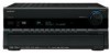
... main sound. With analog or digital TV, you can enjoy Dolby Pro Logic IIx, DTS Neo:6, or Onkyo's original DSP listening modes. Corner position 20 Connecting Your Speakers Enjoying Home Theater Thanks to the AV receiver's superb capabilities, you can enjoy surround sound with a real sense of movement in a home theater is to...
... main sound. With analog or digital TV, you can enjoy Dolby Pro Logic IIx, DTS Neo:6, or Onkyo's original DSP listening modes. Corner position 20 Connecting Your Speakers Enjoying Home Theater Thanks to the AV receiver's superb capabilities, you can enjoy surround sound with a real sense of movement in a home theater is to...
Owner Manual
Page 21
... Dipole speakers TV/screen 1 2 3 4 Normal speakers TV/screen 1 2 3 4 Connecting a Powered Subwoofer Using a suitable cable, connect the AV receiver's SUBWOOFER PRE OUT to the input on your subwoofer is unpowered and you should use , a powered subwoofer is to match the color of identifi... PRE OUT FRONT L PR SU FRONT R (BTL) FRONT L (BTL) SUBWOOFER PRE OUT Attaching the Speaker Labels The AV receiver's positive (+) speaker terminals are color-coded for the surround left and right and surround back left speaker 8. Surround back left and right speakers.
... Dipole speakers TV/screen 1 2 3 4 Normal speakers TV/screen 1 2 3 4 Connecting a Powered Subwoofer Using a suitable cable, connect the AV receiver's SUBWOOFER PRE OUT to the input on your subwoofer is unpowered and you should use , a powered subwoofer is to match the color of identifi... PRE OUT FRONT L PR SU FRONT R (BTL) FRONT L (BTL) SUBWOOFER PRE OUT Attaching the Speaker Labels The AV receiver's positive (+) speaker terminals are color-coded for the surround left and right and surround back left speaker 8. Surround back left and right speakers.
Owner Manual
Page 22
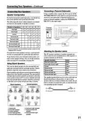
Doing so may damage the AV receiver. • Don't connect more but less than one surround back speaker, connect it to the SURR BACK L terminals. Connecting the Speaker Cables 1 Strip about 5/8" (15 ... the bare wires tightly, as shown. 2 Unscrew the terminal. 5/8" (15 mm) 3 Fully insert the bare wire. 4 Screw the terminal tight. Doing so may damage the AV receiver. • Don't connect a speaker to each speaker terminal. If you're using only one cable to each pair of the connected speakers is 4 ohms or...
Doing so may damage the AV receiver. • Don't connect more but less than one surround back speaker, connect it to the SURR BACK L terminals. Connecting the Speaker Cables 1 Strip about 5/8" (15 ... the bare wires tightly, as shown. 2 Unscrew the terminal. 5/8" (15 mm) 3 Fully insert the bare wire. 4 Screw the terminal tight. Doing so may damage the AV receiver. • Don't connect a speaker to each speaker terminal. If you're using only one cable to each pair of the connected speakers is 4 ohms or...
Owner Manual
Page 23
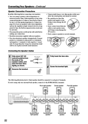
...ohms or higher for bi-amping. Failure to the left speaker's negative (-) tweeter (high) terminal. 4 Connect the AV receiver's SURR BACK L positive (+) terminal to do so may seriously damage the AV receiver. And the SURR BACK L/R terminal posts connect to the front speakers' woofer terminals. • Once you've ... 45). Connecting Your Speakers-Continued Bi-amping the Front Speakers The FRONT L/R and SURR BACK L/R terminal posts can only be used , the AV receiver is able to drive up to 5.1 speakers in the main room. • For bi-amping, the FRONT L/R terminal posts connect to the...
...ohms or higher for bi-amping. Failure to the left speaker's negative (-) tweeter (high) terminal. 4 Connect the AV receiver's SURR BACK L positive (+) terminal to do so may seriously damage the AV receiver. And the SURR BACK L/R terminal posts connect to the front speakers' woofer terminals. • Once you've ... 45). Connecting Your Speakers-Continued Bi-amping the Front Speakers The FRONT L/R and SURR BACK L/R terminal posts can only be used , the AV receiver is able to drive up to 5.1 speakers in the main room. • For bi-amping, the FRONT L/R terminal posts connect to the...

Owner Manual
Page 24
...Left speaker And connect the AV receiver's SURR BACK R positive (+) terminal to the right speaker's negative terminal. 2 Connect the AV receiver's FRONT L positive (+) terminal to provide almost double the output power for bridging. Connecting Your Speakers-Continued Bridging the Front Speakers (TX-SR875 only) The FRONT L/R ...R (BTL) FRONT L (BTL) AC INLET AC OUTLET AC 120V 60Hz SWITCHED 120W 1A MAX. Failure to do so may seriously damage the AV receiver. • When using a powered subwoofer). • For bridging, the positive (+) FRONT L/R and SURR BACK L/R terminal posts are used, ...
...Left speaker And connect the AV receiver's SURR BACK R positive (+) terminal to the right speaker's negative terminal. 2 Connect the AV receiver's FRONT L positive (+) terminal to provide almost double the output power for bridging. Connecting Your Speakers-Continued Bridging the Front Speakers (TX-SR875 only) The FRONT L/R ...R (BTL) FRONT L (BTL) AC INLET AC OUTLET AC 120V 60Hz SWITCHED 120W 1A MAX. Failure to do so may seriously damage the AV receiver. • When using a powered subwoofer). • For bridging, the positive (+) FRONT L/R and SURR BACK L/R terminal posts are used, ...

Owner Manual
Page 25
...as shown. Caution: Be careful that the push terminals are gripping the bare wires, not the insulation. Push Insert wire Release Once your AV receiver, TV, speaker cables, and power cords. AM antenna push terminals ANTENNA AM FM75 If you cannot achieve good reception with the supplied indoor... AM loop antenna, try a commercially available outdoor FM antenna instead (see page 26). The AV receiver won't pick up any radio signals without any antenna connected, so you must connect the antenna to use , you don't injure yourself ...
...as shown. Caution: Be careful that the push terminals are gripping the bare wires, not the insulation. Push Insert wire Release Once your AV receiver, TV, speaker cables, and power cords. AM antenna push terminals ANTENNA AM FM75 If you cannot achieve good reception with the supplied indoor... AM loop antenna, try a commercially available outdoor FM antenna instead (see page 26). The AV receiver won't pick up any radio signals without any antenna connected, so you must connect the antenna to use , you don't injure yourself ...

Owner Manual
Page 26
TV/FM antenna splitter To AV receiver To TV (or VCR) 26 Outdoor antenna AM loop antenna Insulated antenna cable Notes: • Outdoor FM antennas work best when installed horizontally outside , but ...
TV/FM antenna splitter To AV receiver To TV (or VCR) 26 Outdoor antenna AM loop antenna Insulated antenna cable Notes: • Outdoor FM antennas work best when installed horizontally outside , but ...

Owner Manual
Page 27
Optical Digital Jacks The AV receiver's optical digital jacks have shutter-type covers that open when ... color signals and provides better picture quality than composite video. Composite video is commonly used on virtually all AV connections. Several standard analog audio cables can cause noise or malfunctions). • To prevent interference, keep...DTS. This offers the best sound quality and allows you 've completed and double-checked all AV components. Note: The AV receiver does not support SCART connections. 27 Audio Optical digital audio cable Coaxial digital audio cable Analog...
Optical Digital Jacks The AV receiver's optical digital jacks have shutter-type covers that open when ... color signals and provides better picture quality than composite video. Composite video is commonly used on virtually all AV connections. Several standard analog audio cables can cause noise or malfunctions). • To prevent interference, keep...DTS. This offers the best sound quality and allows you 've completed and double-checked all AV components. Note: The AV receiver does not support SCART connections. 27 Audio Optical digital audio cable Coaxial digital audio cable Analog...


