Owner Manual
Page 1
AV Receiver TX-SR800 Instruction Manual Contents Before using 2 Facilities and connections 8 Setup and operation 29 Thank you to obtain optimum performance and listening enjoyment from your new AV Receiver. Please read this manual thoroughly before making connections and plugging in this manual for purchasing the Onkyo AV Receiver. Following the instructions in the unit. Remote controller 61 Appendix 73 E Please retain this manual will enable you for future reference.
AV Receiver TX-SR800 Instruction Manual Contents Before using 2 Facilities and connections 8 Setup and operation 29 Thank you to obtain optimum performance and listening enjoyment from your new AV Receiver. Please read this manual thoroughly before making connections and plugging in this manual for purchasing the Onkyo AV Receiver. Following the instructions in the unit. Remote controller 61 Appendix 73 E Please retain this manual will enable you for future reference.
Owner Manual
Page 3
...FITTED MOULDED PLUG IS UNSUITABLE FOR THE SOCKET OUTLET IN YOUR HOME THEN THE FUSE SHOULD BE REMOVED AND THE PLUG CUT OFF ...receiver. • Connect the equipment into an outlet on a circuit different from heat sources such as follows: The wire which is colored blue must be placed on , contact your area before plugging in the mains lead of the FCC Rules. For Canadian models NOTE: THIS CLASS B DIGITAL... harmful interference in accordance with the colored markings identifying the terminals in your Onkyo authorized service station. 3. These limits are required, be performed only by ...
...FITTED MOULDED PLUG IS UNSUITABLE FOR THE SOCKET OUTLET IN YOUR HOME THEN THE FUSE SHOULD BE REMOVED AND THE PLUG CUT OFF ...receiver. • Connect the equipment into an outlet on a circuit different from heat sources such as follows: The wire which is colored blue must be placed on , contact your area before plugging in the mains lead of the FCC Rules. For Canadian models NOTE: THIS CLASS B DIGITAL... harmful interference in accordance with the colored markings identifying the terminals in your Onkyo authorized service station. 3. These limits are required, be performed only by ...
Owner Manual
Page 6
..."Theater-Dimensional" is a trademark of Onkyo Corporation. • Lucasfilm THX and THX are trademarks or registered trademarks of Digital Theater Systems, Inc. © 1996, 2000 Digital Theater ...digital and analog domains. The following accessories are trademarks of THX Ltd. Though the color varies, the specifications and operations are trademarks of parameters, including power amplifier performance, and pre-amplifier performance and operation for home theater...of the TX-SR800 does not fit your AC outlet. THX Select receivers also feature proprietary THX technologies (e.g., THX Mode, ...
..."Theater-Dimensional" is a trademark of Onkyo Corporation. • Lucasfilm THX and THX are trademarks or registered trademarks of Digital Theater Systems, Inc. © 1996, 2000 Digital Theater ...digital and analog domains. The following accessories are trademarks of THX Ltd. Though the color varies, the specifications and operations are trademarks of parameters, including power amplifier performance, and pre-amplifier performance and operation for home theater...of the TX-SR800 does not fit your AC outlet. THX Select receivers also feature proprietary THX technologies (e.g., THX Mode, ...
Owner Manual
Page 7
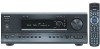
... 1 PRE OUT R L FRONT ANTENNA AUDIO VIDEO S VIDEO MONITOR OUT 2 3 OPT 1 SUB SURR SURR BACK / R ZONE 2 FRONT 2 R SUB 3 DIGITAL OUTPUT OPT SURR R SURR BACK GND CENTER AM OUT ZONE 2 R L L FM 75 MULTI CH INPUT L AUDIO R L CENTER PHONO CD L OUT TAPE ...controller Point the remote controller toward the remote control sensor. The STANDBY indicator lights up when the unit receives a signal from corrosion. If the preset voltage is not correct for your TX-SR800 to conform with two new AA batteries. 7 SELECTOR CENTER SPEAKER R SURR BACK/ L ZONE 2 ...
... 1 PRE OUT R L FRONT ANTENNA AUDIO VIDEO S VIDEO MONITOR OUT 2 3 OPT 1 SUB SURR SURR BACK / R ZONE 2 FRONT 2 R SUB 3 DIGITAL OUTPUT OPT SURR R SURR BACK GND CENTER AM OUT ZONE 2 R L L FM 75 MULTI CH INPUT L AUDIO R L CENTER PHONO CD L OUT TAPE ...controller Point the remote controller toward the remote control sensor. The STANDBY indicator lights up when the unit receives a signal from corrosion. If the preset voltage is not correct for your TX-SR800 to conform with two new AA batteries. 7 SELECTOR CENTER SPEAKER R SURR BACK/ L ZONE 2 ...
Owner Manual
Page 9
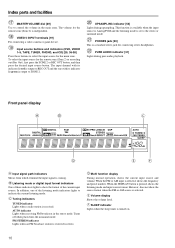
... display MEMORY button [35] Press to MONO and vice versa. When the TX-SR800 is turned on with the receiver plugged in brackets [ ]. In the standby state, the display is turned on the TX-SR800. THX: Selects for the Dolby Pro LogicII, DTS Neo:6, Dolby Digital, or DTS listening modes. ENTER button [40] Press to change the highlighted...
... display MEMORY button [35] Press to MONO and vice versa. When the TX-SR800 is turned on with the receiver plugged in brackets [ ]. In the standby state, the display is turned on the TX-SR800. THX: Selects for the Dolby Pro LogicII, DTS Neo:6, Dolby Digital, or DTS listening modes. ENTER button [40] Press to change the highlighted...
Owner Manual
Page 10
...DVD, VIDEO 1-5, TAPE, TUNER, PHONO, and CD) [29, 36-38] Press these indicators lights to ZONE 2. PHONES jack [30] This is received in stereo. FM STEREO indicator Lights when an FM broadcast station is a standard stereo jack for the main zone. The input channel with its indicator... lit red is output to show the source format when the FM or AM source is selected, shows the frequency and preset number. Listening mode or digital input format indicators One of these buttons to indicate the current listening mode. Tuning indicators TUNED indicator Lights when...
...DVD, VIDEO 1-5, TAPE, TUNER, PHONO, and CD) [29, 36-38] Press these indicators lights to ZONE 2. PHONES jack [30] This is received in stereo. FM STEREO indicator Lights when an FM broadcast station is a standard stereo jack for the main zone. The input channel with its indicator... lit red is output to show the source format when the FM or AM source is selected, shows the frequency and preset number. Listening mode or digital input format indicators One of these buttons to indicate the current listening mode. Tuning indicators TUNED indicator Lights when...
Owner Manual
Page 11
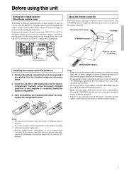
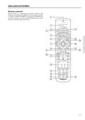
The instructions given here only explain how to place the remote controller in conjunction with the TX-SR800. To operate the TX-SR800 using the remote controller, first press the RCVR MODE button to use the remote controller in the receiver mode. 11 Index parts and facilities Remote controller The RC-510M is a multi-functional remote controller.
The instructions given here only explain how to place the remote controller in conjunction with the TX-SR800. To operate the TX-SR800 using the remote controller, first press the RCVR MODE button to use the remote controller in the receiver mode. 11 Index parts and facilities Remote controller The RC-510M is a multi-functional remote controller.
Owner Manual
Page 13
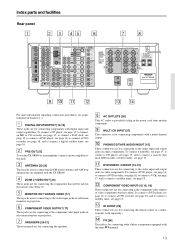
SURR BACK/ ZONE 2 SPEAKERS R L REMOTE CONTROL AV RECEIVER MODEL NO. TX-SR 800 For more information regarding connection procedures, see page 16; PRE OUT [27] To use the TX-SR800 as a preamplifier, connect a power amplifier to connect a satellite tuner, see page 19. COMPONENT VIDEO OUTPUT [17] These jacks are ...15. to connect an MD or CD recorder, see page 17; ANTENNA [22-23] These jacks are for connecting other Onkyo components equipped with digital input and output capabilities. MONITOR OUT VIDEO/S VIDEO [17] These jacks are for connecting to the audio input and output jacks...
SURR BACK/ ZONE 2 SPEAKERS R L REMOTE CONTROL AV RECEIVER MODEL NO. TX-SR 800 For more information regarding connection procedures, see page 16; PRE OUT [27] To use the TX-SR800 as a preamplifier, connect a power amplifier to connect a satellite tuner, see page 19. COMPONENT VIDEO OUTPUT [17] These jacks are ...15. to connect an MD or CD recorder, see page 17; ANTENNA [22-23] These jacks are for connecting other Onkyo components equipped with digital input and output capabilities. MONITOR OUT VIDEO/S VIDEO [17] These jacks are for connecting to the audio input and output jacks...
Owner Manual
Page 21
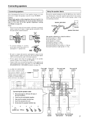
... CORRECT SETTINGS. SURR BACK/ ZONE 2 SPEAKERS R L REMOTE CONTROL AV RECEIVER MODEL NO. Use the PRE OUT SUBWOOFER jack to the amplifier. R StSrUBip away approx. Insert the exposed wire end. Speaker cable label TX-SR800 Speaker Speaker cable label SPEAKERS -+ L L SPEAKERS -+ L L R ...positive speaker terminals on the speaker cables to one speaker is now necessary to connect the speakers correctly to the TX-SR800. DIGITAL OUTPUT Twist R the wire L ends tigCDhtly togethINer. Connecting speakers Connecting speakers After determining the layout of your ...
... CORRECT SETTINGS. SURR BACK/ ZONE 2 SPEAKERS R L REMOTE CONTROL AV RECEIVER MODEL NO. Use the PRE OUT SUBWOOFER jack to the amplifier. R StSrUBip away approx. Insert the exposed wire end. Speaker cable label TX-SR800 Speaker Speaker cable label SPEAKERS -+ L L SPEAKERS -+ L L R ...positive speaker terminals on the speaker cables to one speaker is now necessary to connect the speakers correctly to the TX-SR800. DIGITAL OUTPUT Twist R the wire L ends tigCDhtly togethINer. Connecting speakers Connecting speakers After determining the layout of your ...
Owner Manual
Page 22
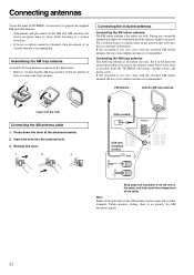
.... 1 2 3 Other models PRE OUT R L ANTENNA AUDIO CENTER R L USA and Canadian models AM R L FM 75 Strip away the insulation from the TX-SR800, televisions, speaker cables, and power cords. Set it with push pins or similar items in the position that will cause the least amount of distortion...to either terminal. Connecting antennas To use the tuner of TX-SR800, it as far away as shown in the illustration. • Refer to "Connecting the AM loop antenna" below for indoor use only. Put it is received. Assembling the AM loop antenna Assemble the loop antenna ...
.... 1 2 3 Other models PRE OUT R L ANTENNA AUDIO CENTER R L USA and Canadian models AM R L FM 75 Strip away the insulation from the TX-SR800, televisions, speaker cables, and power cords. Set it with push pins or similar items in the position that will cause the least amount of distortion...to either terminal. Connecting antennas To use the tuner of TX-SR800, it as far away as shown in the illustration. • Refer to "Connecting the AM loop antenna" below for indoor use only. Put it is received. Assembling the AM loop antenna Assemble the loop antenna ...
Owner Manual
Page 23
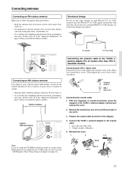
...the wires of the ribbon wire around these screws. Prepare the coaxial cable as shown in a region where AM frequencies are using the TX-SR800 worldwide model in the diagram. 4. Directional linkage Do not use a directional linkage type splitter. If you are delineated by 10-kHz ...Slit C 23 Follow item 14 of lightning and electrical shock, grounding is necessary. PRE OUT R L ANTENNA AUDIO CENTER R L AM R L FM 75 To receiver To TV (or VCR) Connecting the antenna cable to power lines. Then tighten the screws down with the indoor AM antenna, stretch out the outdoor...
...the wires of the ribbon wire around these screws. Prepare the coaxial cable as shown in a region where AM frequencies are using the TX-SR800 worldwide model in the diagram. 4. Directional linkage Do not use a directional linkage type splitter. If you are delineated by 10-kHz ...Slit C 23 Follow item 14 of lightning and electrical shock, grounding is necessary. PRE OUT R L ANTENNA AUDIO CENTER R L AM R L FM 75 To receiver To TV (or VCR) Connecting the antenna cable to power lines. Then tighten the screws down with the indoor AM antenna, stretch out the outdoor...
Owner Manual
Page 25
...select "Zone 2" for the Hardware Setup → IR IN Setup → Position setting in the Setup Menu (see page 42). Connect the mini plug of the TX-SR800 will not be possible. With this situation, you will need to prepare a multi-room kit (sold separately) such as one of those given below: • Onkyo... other components In this connection, select "Main" for the Hardware Setup → IR IN Setup → Position setting in any equipment to the power outlet until all the connections are complete. IR IN Connectiong block IR Receiver TX-SR800 Remote controller In the cabinet :...
...select "Zone 2" for the Hardware Setup → IR IN Setup → Position setting in the Setup Menu (see page 42). Connect the mini plug of the TX-SR800 will not be possible. With this situation, you will need to prepare a multi-room kit (sold separately) such as one of those given below: • Onkyo... other components In this connection, select "Main" for the Hardware Setup → IR IN Setup → Position setting in any equipment to the power outlet until all the connections are complete. IR IN Connectiong block IR Receiver TX-SR800 Remote controller In the cabinet :...
Owner Manual
Page 28
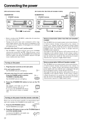
... equipment on the same circuit, such as computers. To return the TX-SR800 to turn on the TX- If this happens, use the remote controller, you press the STANDBY/ON button STANDBY again, the receiver returns to a highly humid climate. STANDBY (All models other than ... MEMORY CLEAR TAPE TUNER PHONO C D MASTER VOLUME VIDEO 5 INPUT DIGITAL S VIDEO VIDEO L AUDIO R TX-SR800 STANDBY/ON STANDBY indicator ON STANDBY RCVR STANDBY/ON DISPLAY DIMMER STANDBY POWER ON OFF PURE AUDIO UPSAMPLING DIRECT/PURE AUDIO STEREO SURROUND THX DSP PHONES AUDIO SELECTOR ZONE 2 (GRN ) REC ( RED )...
... equipment on the same circuit, such as computers. To return the TX-SR800 to turn on the TX- If this happens, use the remote controller, you press the STANDBY/ON button STANDBY again, the receiver returns to a highly humid climate. STANDBY (All models other than ... MEMORY CLEAR TAPE TUNER PHONO C D MASTER VOLUME VIDEO 5 INPUT DIGITAL S VIDEO VIDEO L AUDIO R TX-SR800 STANDBY/ON STANDBY indicator ON STANDBY RCVR STANDBY/ON DISPLAY DIMMER STANDBY POWER ON OFF PURE AUDIO UPSAMPLING DIRECT/PURE AUDIO STEREO SURROUND THX DSP PHONES AUDIO SELECTOR ZONE 2 (GRN ) REC ( RED )...
Owner Manual
Page 34
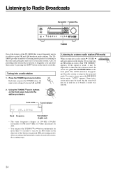
...THX DSP PHONES AUDIO SELECTOR ZONE 2 (GRN ) REC ( RED ) DVD VIDEO 1 VIDEO 2 VIDEO 3 VIDEO 4 VIDEO 5 VCR 1 VCR 2 REC OUT ZONE 2 OFF TUNING SETUP ENTER PRESET RE TURN MEMORY FM MODE A-FORM LISTENING MODE MEMORY CLEAR TAPE TUNER PHONO C D MASTER VOLUME VIDEO 5 INPUT DIGITAL S VIDEO VIDEO L AUDIO R TX-SR800...) increments for AM. • You can select them easily by presetting radio stations that is output...TX-SR800 that you listen to frequently, you release the button and a station is its ability to the radio and getting the most frequently used is received...
...THX DSP PHONES AUDIO SELECTOR ZONE 2 (GRN ) REC ( RED ) DVD VIDEO 1 VIDEO 2 VIDEO 3 VIDEO 4 VIDEO 5 VCR 1 VCR 2 REC OUT ZONE 2 OFF TUNING SETUP ENTER PRESET RE TURN MEMORY FM MODE A-FORM LISTENING MODE MEMORY CLEAR TAPE TUNER PHONO C D MASTER VOLUME VIDEO 5 INPUT DIGITAL S VIDEO VIDEO L AUDIO R TX-SR800...) increments for AM. • You can select them easily by presetting radio stations that is output...TX-SR800 that you listen to frequently, you release the button and a station is its ability to the radio and getting the most frequently used is received...
Owner Manual
Page 39
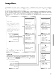
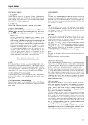
...selected input source. 0.Hardware Setup Basic Menu Your TX-SR800 is provided with a Basic Menu for those who are not familiar with many of the advanced settings of an AV receiver...of the TX-SR800. The actual contents of your display may differ depending on the model of your television monitor and the display on your home theater as the ...Speaker Setup 1.Speaker Config 2.Speaker Distance 3.Level Calibration |ENTER|Quit:|SETUP| 2.Input Setup Input:DVD 1.Digital Setup 2.Multichannel Setup 3.Video Setup 4.Character Input 5.IntelliVolume 6.Listening Mode Preset |ENTER|Quit:|SETUP| 3.Audio...
...selected input source. 0.Hardware Setup Basic Menu Your TX-SR800 is provided with a Basic Menu for those who are not familiar with many of the advanced settings of an AV receiver...of the TX-SR800. The actual contents of your display may differ depending on the model of your television monitor and the display on your home theater as the ...Speaker Setup 1.Speaker Config 2.Speaker Distance 3.Level Calibration |ENTER|Quit:|SETUP| 2.Input Setup Input:DVD 1.Digital Setup 2.Multichannel Setup 3.Video Setup 4.Character Input 5.IntelliVolume 6.Listening Mode Preset |ENTER|Quit:|SETUP| 3.Audio...
Owner Manual
Page 51
...signal comes from DVDs, compact discs, and LDs that cannot be sure to set up your home theater, it may see the message "Dialog Norm: +4" in its original 5.1-channel form. Dialog ...T-D (Theater-Dimensional) For the best enjoyment of the TX-SR800, the relay switch doesn't activate and signals are output to minimize reflective sound. This mode controls the characteristics of digital audio signals...from DVDs and LDs that allows for playing the left and right front speakers. To receive the full effect, there is recorded directly onto compact discs and DVDs without compression. ...
...signal comes from DVDs, compact discs, and LDs that cannot be sure to set up your home theater, it may see the message "Dialog Norm: +4" in its original 5.1-channel form. Dialog ...T-D (Theater-Dimensional) For the best enjoyment of the TX-SR800, the relay switch doesn't activate and signals are output to minimize reflective sound. This mode controls the characteristics of digital audio signals...from DVDs and LDs that allows for playing the left and right front speakers. To receive the full effect, there is recorded directly onto compact discs and DVDs without compression. ...
Owner Manual
Page 73
... received. • AM loop antenna is not connected. © Connect the included AM loop antenna to any mode other wiring (see page 53). Troubleshooting guide If a problem occurs while you are using the remote controller, first try to operate the controls on the front panel of the TX-SR800... to make sure that has better directivity and orient it is not due to correct input source. • Headphones are connected. © Lower volume and then disconnect headphones. Contact your Onkyo service center.
... received. • AM loop antenna is not connected. © Connect the included AM loop antenna to any mode other wiring (see page 53). Troubleshooting guide If a problem occurs while you are using the remote controller, first try to operate the controls on the front panel of the TX-SR800... to make sure that has better directivity and orient it is not due to correct input source. • Headphones are connected. © Lower volume and then disconnect headphones. Contact your Onkyo service center.
Owner Manual
Page 74
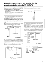
...not heard with DTS sources, PCM sources, and other digital formats are incorrect. © Check settings at the remote sensor of the TX- SR800. © Point the remote controller at Setup Menu ... required to current listening mode. © Select different listening mode (see page 48). SR800 (see page 7). • Remote controller is too far from the TX-SR800. © Operate the remote controller within...remote controller signals. © Move inferring objects away from the receiver. © Set the TV (or monitor) to the receiver input. • Video cable is not connected securely. &#...
...not heard with DTS sources, PCM sources, and other digital formats are incorrect. © Check settings at the remote sensor of the TX- SR800. © Point the remote controller at Setup Menu ... required to current listening mode. © Select different listening mode (see page 48). SR800 (see page 7). • Remote controller is too far from the TX-SR800. © Operate the remote controller within...remote controller signals. © Move inferring objects away from the receiver. © Set the TV (or monitor) to the receiver input. • Video cable is not connected securely. &#...


