
Owner Manual
Page 7
...AV Receiver/AV Amplifier 15 About Home Theater 16 Enjoying Home Theater 16 Connections Connecting the AV Receiver/AV Amplifier 17 Connecting Your Speakers 17 Bi-amping the Front Speakers 19 Connecting Antenna (TX-SR706 only 20 About AV...89 Hardware Setup 91 Lock Setup 95 Automatic Audio Input Selection Setup 96 Digital Input Signal Formats 96 Zone 2 Zone 2 97 Connecting Zone 2 97 Setting the Powered Zone ... Remote Control Codes 102 Entering Remote Control Codes 102 Remote Control Codes for Onkyo Components Connected via V 103 Resetting REMOTE MODE Buttons 103 Resetting the Remote ...
...AV Receiver/AV Amplifier 15 About Home Theater 16 Enjoying Home Theater 16 Connections Connecting the AV Receiver/AV Amplifier 17 Connecting Your Speakers 17 Bi-amping the Front Speakers 19 Connecting Antenna (TX-SR706 only 20 About AV...89 Hardware Setup 91 Lock Setup 95 Automatic Audio Input Selection Setup 96 Digital Input Signal Formats 96 Zone 2 Zone 2 97 Connecting Zone 2 97 Setting the Powered Zone ... Remote Control Codes 102 Entering Remote Control Codes 102 Remote Control Codes for Onkyo Components Connected via V 103 Resetting REMOTE MODE Buttons 103 Resetting the Remote ...

Owner Manual
Page 9
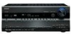
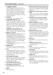
...ZONE 2 indicator (99) This indicator lights up when this button again selects the previous listening mode. F Remote control sensor (14) This sensor receives control signals from the following input sources: MULTI CH, DVD, VCR/DVR, CBL/SAT, GAME/TV, AUX, TAPE, TUNER, CD, PHONO. When the... selector buttons (54) These buttons are used to select and set the AV receiver/AV amplifier to turn off . G Display See "Display" on . H SETUP button This button is used to select radio presets (see page 58) (TX-SR706 only). K MASTER VOLUME control (54) and indicator This control is selected...
...ZONE 2 indicator (99) This indicator lights up when this button again selects the previous listening mode. F Remote control sensor (14) This sensor receives control signals from the following input sources: MULTI CH, DVD, VCR/DVR, CBL/SAT, GAME/TV, AUX, TAPE, TUNER, CD, PHONO. When the... selector buttons (54) These buttons are used to select and set the AV receiver/AV amplifier to turn off . G Display See "Display" on . H SETUP button This button is used to select radio presets (see page 58) (TX-SR706 only). K MASTER VOLUME control (54) and indicator This control is selected...

Owner Manual
Page 10
... (54) Displays the volume level. Front & Rear Panels-Continued Display 12 3 45 67 For detailed information, see the pages in the current input signal. B Speaker/channel indicators (73) Indicate the speaker configuration and channels used . TUNED (57): Lights up when tuned to a stereo FM station. ...tuned to "No" or "None". No box appears for AM or FM radio. L MUTING indicator (56) Flashes while the AV receiver/AV amplifier is selected. E Tuning indicators (TX-SR706 only) (57) RDS (not North American model) (59): Lights up when the Sleep function has been set to a radio ...
... (54) Displays the volume level. Front & Rear Panels-Continued Display 12 3 45 67 For detailed information, see the pages in the current input signal. B Speaker/channel indicators (73) Indicate the speaker configuration and channels used . TUNED (57): Lights up when tuned to a stereo FM station. ...tuned to "No" or "None". No box appears for AM or FM radio. L MUTING indicator (56) Flashes while the AV receiver/AV amplifier is selected. E Tuning indicators (TX-SR706 only) (57) RDS (not North American model) (59): Lights up when the Sleep function has been set to a radio ...
Owner Manual
Page 12
... the power cord should be used to an V jack on the AV receiver/AV amplifier, a 12volt trigger signal is connected here. D COMPONENT VIDEO IN 1 and 2 These RCA...DVD recorder, or DVR (digital video recorder). When Zone 2 is turned on on another Onkyo AV component. K RS232 This is the RS232 port. 12 L XM antenna (North American ...receiver, settop box, etc. See "Component Video Setup" on page 44. H 12V TRIGGER OUT ZONE 2 This output can be connected to a suitable wall outlet. J AM ANTENNA (TX-SR706 only) These push terminals are for connecting an AM antenna. The other AV...
... the power cord should be used to an V jack on the AV receiver/AV amplifier, a 12volt trigger signal is connected here. D COMPONENT VIDEO IN 1 and 2 These RCA...DVD recorder, or DVR (digital video recorder). When Zone 2 is turned on on another Onkyo AV component. K RS232 This is the RS232 port. 12 L XM antenna (North American ...receiver, settop box, etc. See "Component Video Setup" on page 44. H 12V TRIGGER OUT ZONE 2 This output can be connected to a suitable wall outlet. J AM ANTENNA (TX-SR706 only) These push terminals are for connecting an AM antenna. The other AV...

Owner Manual
Page 20
... jack. ■ Other models 2 Connect both wires of the AM antenna to tune into the jack. Connecting the AV Receiver/AV Amplifier-Continued Connecting Antenna (TX-SR706 only) This section explains how to connect the supplied indoor FM antenna and AM loop antenna, and how to use ...insulation. Thumbtacks, etc. If you must connect the antenna to connect commercially available outdoor FM and AM antennas. The AV receiver won't pick up any radio signals without any antenna connected, so you cannot achieve good reception with the supplied indoor AM loop antenna, try a commercially...
... jack. ■ Other models 2 Connect both wires of the AM antenna to tune into the jack. Connecting the AV Receiver/AV Amplifier-Continued Connecting Antenna (TX-SR706 only) This section explains how to connect the supplied indoor FM antenna and AM loop antenna, and how to use ...insulation. Thumbtacks, etc. If you must connect the antenna to connect commercially available outdoor FM and AM antennas. The AV receiver won't pick up any radio signals without any antenna connected, so you cannot achieve good reception with the supplied indoor AM loop antenna, try a commercially...

Owner Manual
Page 22
... and double-checked all AV components. Optical Digital Jacks The AV receiver/AV amplifier's optical digital jacks have shutter-type covers that open when an optical plug is the same as for coaxial. Component video separates the luminance (Y) and color difference signals (PR, PB), providing...used to connect left-channel audio inputs and outputs (typically labeled "L"). HDMI dard- This cable carries analog audio. Note: The AV receiver/AV amplifier does not support SCART plugs. 22 Use white plugs to connect DVD players with your other video equipment. Right (red)...
... and double-checked all AV components. Optical Digital Jacks The AV receiver/AV amplifier's optical digital jacks have shutter-type covers that open when an optical plug is the same as for coaxial. Component video separates the luminance (Y) and color difference signals (PR, PB), providing...used to connect left-channel audio inputs and outputs (typically labeled "L"). HDMI dard- This cable carries analog audio. Note: The AV receiver/AV amplifier does not support SCART plugs. 22 Use white plugs to connect DVD players with your other video equipment. Right (red)...

Owner Manual
Page 23
...an input selector (see page 18 for connection information) Which Connections Should I Use? The AV receiver/AV amplifier supports several connection formats for compatibility with composite Video Signal Flow Chart video, S-Video, and component video sources all being upconverted for the HDMI output...TV, projector, etc. 23 Video input signals flow through their respective input IN signals as shown, with a wide range of your DVD player and other components. Speakers (see pages 42 and 43). Connecting the AV Receiver/AV Amplifier-Continued Connecting Both Audio & Video ...
...an input selector (see page 18 for connection information) Which Connections Should I Use? The AV receiver/AV amplifier supports several connection formats for compatibility with composite Video Signal Flow Chart video, S-Video, and component video sources all being upconverted for the HDMI output...TV, projector, etc. 23 Video input signals flow through their respective input IN signals as shown, with a wide range of your DVD player and other components. Speakers (see pages 42 and 43). Connecting the AV Receiver/AV Amplifier-Continued Connecting Both Audio & Video ...
Owner Manual
Page 24
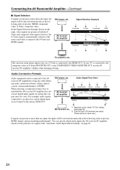
... to the composite video or S-Video MONITOR OUT, or the COMPONENT VIDEO MONITOR OUT, use the AV receiver/AV amplifier's display when changing settings. Connecting the AV Receiver/AV Amplifier-Continued ■ Signal Selection If signals are present at more than one input, the inputs will be selected automatically in the following order of priority: HDMI, digital, analog...
... to the composite video or S-Video MONITOR OUT, or the COMPONENT VIDEO MONITOR OUT, use the AV receiver/AV amplifier's display when changing settings. Connecting the AV Receiver/AV Amplifier-Continued ■ Signal Selection If signals are present at more than one input, the inputs will be selected automatically in the following order of priority: HDMI, digital, analog...

Owner Manual
Page 25
...well, use its tuner to listen to TV programs through the AV receiver/AV amplifier (see page 44) TV, projector, etc. Hint! If your TV is connected to the HDMI OUT. Connecting the AV Receiver/AV Amplifier-Continued Connecting a TV or Projector See "Connecting Components with ... cable or satellite receiver to the AV receiver/AV amplifier and use a and b , or a and c .) Connection A B C a b c AV receiver/AV amplifier COMPONENT VIDEO MONITOR OUT MONITOR OUT S MONITOR OUT V GAME/TV IN L/R DIGITAL COAXIAL IN 2 (VCR/DVR) DIGITAL OPTICAL IN 1 (GAME/TV) Signal flow TV Component video...
...well, use its tuner to listen to TV programs through the AV receiver/AV amplifier (see page 44) TV, projector, etc. Hint! If your TV is connected to the HDMI OUT. Connecting the AV Receiver/AV Amplifier-Continued Connecting a TV or Projector See "Connecting Components with ... cable or satellite receiver to the AV receiver/AV amplifier and use a and b , or a and c .) Connection A B C a b c AV receiver/AV amplifier COMPONENT VIDEO MONITOR OUT MONITOR OUT S MONITOR OUT V GAME/TV IN L/R DIGITAL COAXIAL IN 2 (VCR/DVR) DIGITAL OPTICAL IN 1 (GAME/TV) Signal flow TV Component video...

Owner Manual
Page 26
Connection A B C a b c AV receiver/AV amplifier COMPONENT VIDEO IN 1 (DVD) DVD S DVD V DVD FRONT L/R DIGITAL COAXIAL IN 1 (DVD) DIGITAL OPTICAL IN 1 (GAME/TV) Signal flow DVD player Component video output S-Video output Composite video output Analog ...audio L/R output Digital coaxial output Digital optical output b c A C B a COAXIAL OUT OPTICAL OUT Y PB PR COMPONENT VIDEO OUT L R AUDIO OUT S VIDEO OUT VIDEO OUT Connect one or the other Connection c must connect the AV receiver/AV...
Connection A B C a b c AV receiver/AV amplifier COMPONENT VIDEO IN 1 (DVD) DVD S DVD V DVD FRONT L/R DIGITAL COAXIAL IN 1 (DVD) DIGITAL OPTICAL IN 1 (GAME/TV) Signal flow DVD player Component video output S-Video output Composite video output Analog ...audio L/R output Digital coaxial output Digital optical output b c A C B a COAXIAL OUT OPTICAL OUT Y PB PR COMPONENT VIDEO OUT L R AUDIO OUT S VIDEO OUT VIDEO OUT Connect one or the other Connection c must connect the AV receiver/AV...
Owner Manual
Page 27
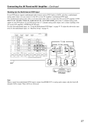
...RL SUB SURROUND WOOFER R SURR BACK DVD player Note: When a signal from multichannel DVD input is output from HDMI OUT or analog audio output, only the front L/R channels will be output. Connecting the AV Receiver/AV Amplifier-Continued Hooking Up the Multichannel DVD Input If your DVD player ...it has a multichannel analog audio output, you can connect it to the AV receiver/AV amplifier's SURR BACK L/R jacks. Use a multichannel analog audio cable, or several normal audio cables, to connect the AV receiver/AV amplifier's DVD FRONT L/R, CENTER, SURR L/R, SURR BACK L/R, and SUBWOOFER ...
...RL SUB SURROUND WOOFER R SURR BACK DVD player Note: When a signal from multichannel DVD input is output from HDMI OUT or analog audio output, only the front L/R channels will be output. Connecting the AV Receiver/AV Amplifier-Continued Hooking Up the Multichannel DVD Input If your DVD player ...it has a multichannel analog audio output, you can connect it to the AV receiver/AV amplifier's SURR BACK L/R jacks. Use a multichannel analog audio cable, or several normal audio cables, to connect the AV receiver/AV amplifier's DVD FRONT L/R, CENTER, SURR L/R, SURR BACK L/R, and SUBWOOFER ...

Owner Manual
Page 28
AV receiver/AV amplifier COMPONENT VIDEO IN 2 (CBL/SAT) VCR/DVR IN S VCR/DVR IN V VCR/DVR IN L/R DIGITAL COAXIAL IN 2 (VCR/DVR) DIGITAL OPTICAL IN 1 (GAME/TV) Signal flow VCR or DVD recorder Component video output S-Video output Composite video output Analog audio L/R... output Digital coaxial output Digital optical output Connection A must be assigned (see page 43) b c A C B a COAXIAL OUT OPTICAL OUT Connect one or the other Connection c must connect the AV receiver/AV...
AV receiver/AV amplifier COMPONENT VIDEO IN 2 (CBL/SAT) VCR/DVR IN S VCR/DVR IN V VCR/DVR IN L/R DIGITAL COAXIAL IN 2 (VCR/DVR) DIGITAL OPTICAL IN 1 (GAME/TV) Signal flow VCR or DVD recorder Component video output S-Video output Composite video output Analog audio L/R... output Digital coaxial output Digital optical output Connection A must be assigned (see page 43) b c A C B a COAXIAL OUT OPTICAL OUT Connect one or the other Connection c must connect the AV receiver/AV...
Owner Manual
Page 29
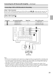
...is not possible while it's in Standby mode. • If you want to a composite video output. Similarly, video signals connected to the AV receiver/AV amplifier via the same type of connection. The video source to be recorded must be connected to composite video inputs can ...Video inputs can only be recorded via composite video outputs. If your TV and VCR for recording. Connection A B a AV receiver/AV amplifier VCR/DVR OUT S VCR/DVR OUT V VCR/DVR OUT L/R Signal flow ⇒ ⇒ ⇒ VCR or DVD recorder S-Video input Composite video input Analog audio L/R input CB...
...is not possible while it's in Standby mode. • If you want to a composite video output. Similarly, video signals connected to the AV receiver/AV amplifier via the same type of connection. The video source to be recorded must be connected to composite video inputs can ...Video inputs can only be recorded via composite video outputs. If your TV and VCR for recording. Connection A B a AV receiver/AV amplifier VCR/DVR OUT S VCR/DVR OUT V VCR/DVR OUT L/R Signal flow ⇒ ⇒ ⇒ VCR or DVD recorder S-Video input Composite video input Analog audio L/R input CB...

Owner Manual
Page 30
... no audio outputs. With this hookup, you can use a and b , or a and c .) Connection A B C a b c AV receiver/AV amplifier COMPONENT VIDEO IN 2 (CBL/SAT) CBL/SAT IN S CBL/SAT IN V CBL/SAT IN L/R DIGITAL COAXIAL IN 3 (CBL/SAT) DIGITAL OPTICAL IN 2 (CD) Signal flow Video source Component video output S-Video output Composite video output Analog audio...
... no audio outputs. With this hookup, you can use a and b , or a and c .) Connection A B C a b c AV receiver/AV amplifier COMPONENT VIDEO IN 2 (CBL/SAT) CBL/SAT IN S CBL/SAT IN V CBL/SAT IN L/R DIGITAL COAXIAL IN 3 (CBL/SAT) DIGITAL OPTICAL IN 2 (CD) Signal flow Video source Component video output S-Video output Composite video output Analog audio...

Owner Manual
Page 31
... and DTS, use connection b . (To record or listen in Zone 2 as well, use a and b .) Connection A B C a b AV receiver/AV amplifier COMPONENT VIDEO IN 2 (CBL/SAT) GAME/TV IN S GAME/TV IN V GAME/TV IN L/R DIGITAL OPTICAL IN 1 (GAME/TV) Signal flow Game console Component video output S-Video output Composite video output Analog audio L/R output Digital...
... and DTS, use connection b . (To record or listen in Zone 2 as well, use a and b .) Connection A B C a b AV receiver/AV amplifier COMPONENT VIDEO IN 2 (CBL/SAT) GAME/TV IN S GAME/TV IN V GAME/TV IN L/R DIGITAL OPTICAL IN 1 (GAME/TV) Signal flow Game console Component video output S-Video output Composite video output Analog audio L/R output Digital...

Owner Manual
Page 32
Signal flow Camcorder etc. AUX INPUT S VIDEO AUX INPUT VIDEO A B AUX INPUT DIGITAL b AUX INPUT L AUDIO R a S VIDEO OUT VIDEO OUT L AUDIO R OUT OPTICAL OUT Connection A B a b AV receiver/AV amplifier AUX INPUT S VIDEO AUX INPUT VIDEO AUX INPUT L-AUDIO-R AUX INPUT DIGITAL Camcorder, etc. Connecting the AV Receiver/AV Amplifier-Continued Connecting a Camcorder or Other Device Step 1: Video Connection...
Signal flow Camcorder etc. AUX INPUT S VIDEO AUX INPUT VIDEO A B AUX INPUT DIGITAL b AUX INPUT L AUDIO R a S VIDEO OUT VIDEO OUT L AUDIO R OUT OPTICAL OUT Connection A B a b AV receiver/AV amplifier AUX INPUT S VIDEO AUX INPUT VIDEO AUX INPUT L-AUDIO-R AUX INPUT DIGITAL Camcorder, etc. Connecting the AV Receiver/AV Amplifier-Continued Connecting a Camcorder or Other Device Step 1: Video Connection...
Owner Manual
Page 33
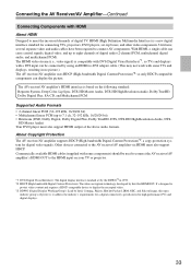
... standard set -top boxes, and other video components. About Copyright Protection The AV receiver/AV amplifier supports HDCP (High-bandwidth Digital Content Protection)*2, a copy-protection system for digital video signals. Commercially available HDMI cables (supplied with some components) should be connected by ...20/24 bit) • Multichannel linear PCM (up to connect AV components. The AV receiver/AV amplifier's HDMI interface is compatible with DVI (Digital Visual Interface)*1, so TVs and displays with a DVI input can carry control signals, digital video, and up to 7.1 ch, 32-192 kHz...
... standard set -top boxes, and other video components. About Copyright Protection The AV receiver/AV amplifier supports HDCP (High-bandwidth Digital Content Protection)*2, a copy-protection system for digital video signals. Commercially available HDMI cables (supplied with some components) should be connected by ...20/24 bit) • Multichannel linear PCM (up to connect AV components. The AV receiver/AV amplifier's HDMI interface is compatible with DVI (Digital Visual Interface)*1, so TVs and displays with a DVI input can carry control signals, digital video, and up to 7.1 ch, 32-192 kHz...

Owner Manual
Page 34
...8226; When listening to an HDMI component through the AV receiver/AV amplifier, set the HDMI component so that DVI connections only carry video, so you turn down the AV receiver/AV amplifier's volume. • The HDMI audio signal (sampling rate, bit length, etc.) may be cut... AV Receiver/AV Amplifier-Continued Making HDMI Connections Step 1: Use HDMI cables to connect the AV receiver/AV amplifier's HDMI jacks to your TV's settings, or turn up the AV receiver/AV amplifier volume control, the sound will be output by the AV receiver/AV amplifier's speakers. In addition, video signals ...
...8226; When listening to an HDMI component through the AV receiver/AV amplifier, set the HDMI component so that DVI connections only carry video, so you turn down the AV receiver/AV amplifier's volume. • The HDMI audio signal (sampling rate, bit length, etc.) may be cut... AV Receiver/AV Amplifier-Continued Making HDMI Connections Step 1: Use HDMI cables to connect the AV receiver/AV amplifier's HDMI jacks to your TV's settings, or turn up the AV receiver/AV amplifier volume control, the sound will be output by the AV receiver/AV amplifier's speakers. In addition, video signals ...

Owner Manual
Page 35
...record or listen in Zone 2 as well, use a and b , or a and c .) Connection a b c AV receiver/AV amplifier CD IN L/R DIGITAL COAXIAL IN 2 (VCR/DVR) DIGITAL OPTICAL IN 2 (CD) Signal flow ⇐ ⇐ ⇐ CD or turntable Analog audio L/R output Digital coaxial output Digital optical output ■ Turntable... (MM) with no Phono Preamp Built-in The AV receiver/AV amplifier's PHONO IN is designed for use a phono...
...record or listen in Zone 2 as well, use a and b , or a and c .) Connection a b c AV receiver/AV amplifier CD IN L/R DIGITAL COAXIAL IN 2 (VCR/DVR) DIGITAL OPTICAL IN 2 (CD) Signal flow ⇐ ⇐ ⇐ CD or turntable Analog audio L/R output Digital coaxial output Digital optical output ■ Turntable... (MM) with no Phono Preamp Built-in The AV receiver/AV amplifier's PHONO IN is designed for use a phono...

Owner Manual
Page 36
Connection a b c AV receiver/AV amplifier Signal flow TAPE IN L/R ⇐ TAPE OUT L/R ⇒ DIGITAL COAXIAL IN 3 (CBL/SAT) ⇐ DIGITAL OPTICAL IN 1 (GAME/TV) ⇐ Cassette, CDR, MD, or DAT recorder Analog audio L/R output Analog audio L/R input Digital coaxial output Digital optical output 36 Connecting the AV Receiver/AV Amplifier-Continued Connecting a Cassette, CDR, MiniDisc, or DAT Recorder...
Connection a b c AV receiver/AV amplifier Signal flow TAPE IN L/R ⇐ TAPE OUT L/R ⇒ DIGITAL COAXIAL IN 3 (CBL/SAT) ⇐ DIGITAL OPTICAL IN 1 (GAME/TV) ⇐ Cassette, CDR, MD, or DAT recorder Analog audio L/R output Analog audio L/R input Digital coaxial output Digital optical output 36 Connecting the AV Receiver/AV Amplifier-Continued Connecting a Cassette, CDR, MiniDisc, or DAT Recorder...
