
Owner Manual
Page 2
...If you 'll need to assign the digital inputs as necessary using the setup menus on the TX-SR606's display. Listening Mode Preset 6. Input Assign 1. Digital audio signals received at HDMI IN inputs are not using Cable/satellite box, please refer to change the default ...AV receiver's HDMI1, and connect your cable/satellite receiver to the COAXIAL 2 DIGITAL IN, as shown above, it 's not necessary to the HDMI OUT. Digital Audio Input 1-1. On the front panel TUNING PRESET SETUP ENTER If your TV or player doesn't support HDMI, use the TX-SR606's display when changing settings...
...If you 'll need to assign the digital inputs as necessary using the setup menus on the TX-SR606's display. Listening Mode Preset 6. Input Assign 1. Digital audio signals received at HDMI IN inputs are not using Cable/satellite box, please refer to change the default ...AV receiver's HDMI1, and connect your cable/satellite receiver to the COAXIAL 2 DIGITAL IN, as shown above, it 's not necessary to the HDMI OUT. Digital Audio Input 1-1. On the front panel TUNING PRESET SETUP ENTER If your TV or player doesn't support HDMI, use the TX-SR606's display when changing settings...

Instruction Manual
Page 2
... adjustment of other apparatus (including amplifiers) that produce heat. 9. When the apparatus exhibits a distinct change in any way, such as vases shall be set 10 cm (4") away from the rear panel or wall, creating a flue-like gap for long periods of any heat sources such as a bookcase or...
... adjustment of other apparatus (including amplifiers) that produce heat. 9. When the apparatus exhibits a distinct change in any way, such as vases shall be set 10 cm (4") away from the rear panel or wall, creating a flue-like gap for long periods of any heat sources such as a bookcase or...

Instruction Manual
Page 3
...Part 15 of the following measures: • Reorient or relocate the receiving antenna. • Increase the separation between 220 and 240 volts, set to the correct voltage for personal use a small screwdriver to set the selector to select Standby mode does not fully shutdown the unit....operate the equipment. Precautions 1. models FCC Information for User CAUTION: The user changes or modifications not expressly approved by your Onkyo dealer. 3. These limits are wet or damp. Dry the unit immediately afterwards with a polarized plug: CAUTION: TO PREVENT ELECTRIC SHOCK...
...Part 15 of the following measures: • Reorient or relocate the receiving antenna. • Increase the separation between 220 and 240 volts, set to the correct voltage for personal use a small screwdriver to set the selector to select Standby mode does not fully shutdown the unit....operate the equipment. Precautions 1. models FCC Information for User CAUTION: The user changes or modifications not expressly approved by your Onkyo dealer. 3. These limits are wet or damp. Dry the unit immediately afterwards with a polarized plug: CAUTION: TO PREVENT ELECTRIC SHOCK...

Instruction Manual
Page 5
... DAT Recorder 34 Connecting an RI Dock 35 Connecting Onkyo Components 36 Turning On the AV Receiver 37 Connecting the Power Cord 37 Turning On and Standby 37 First Time Setup 38 Automatic Speaker Setup 38 Speaker Settings 42 HDMI Input Setup 43 Component Video Input Setup ... 44 Changing the Input Display 45 Automatic Audio Input Selection Setup 46 Playing Your AV Components 47 Basic AV Receiver Operation 47 Common Functions 48 Setting the Display Brightness 48 Muting the AV Receiver 48 Using the Sleep Timer 48 Using Headphones 49 Displaying Source Information 49 Specifying...
... DAT Recorder 34 Connecting an RI Dock 35 Connecting Onkyo Components 36 Turning On the AV Receiver 37 Connecting the Power Cord 37 Turning On and Standby 37 First Time Setup 38 Automatic Speaker Setup 38 Speaker Settings 42 HDMI Input Setup 43 Component Video Input Setup ... 44 Changing the Input Display 45 Automatic Audio Input Selection Setup 46 Playing Your AV Components 47 Basic AV Receiver Operation 47 Common Functions 48 Setting the Display Brightness 48 Muting the AV Receiver 48 Using the Sleep Timer 48 Using Headphones 49 Displaying Source Information 49 Specifying...

Instruction Manual
Page 8
... ZONE 2 LEVEL TONE MOVIE/TV MUSIC GAME DISPLAY DIGITAL INPUT DIMMER MEMORY TUNING MODE CLEAR SETUP MIC AUX INPUT VIDEO L AUDIO R AV RECEIVER TX-SR606 KL M Other models N OPQ RS TUV W ON/STANDBY STANDBY ZONE 2 TUNING PRESET X MASTER VOLUME PURE AUDIO MULTI CH DVD...TP MEMORY TUNING MODE CLEAR SETUP MIC AUX INPUT VIDEO L AUDIO R AV RECEIVER TX-SR606 Y T The actual front panel has various logos printed on page 9. A ON/STANDBY button (37) Sets the AV receiver to select and set . Lights up when the AV receiver is on . F Display See "Display" on it. H TUNING,...
... ZONE 2 LEVEL TONE MOVIE/TV MUSIC GAME DISPLAY DIGITAL INPUT DIMMER MEMORY TUNING MODE CLEAR SETUP MIC AUX INPUT VIDEO L AUDIO R AV RECEIVER TX-SR606 KL M Other models N OPQ RS TUV W ON/STANDBY STANDBY ZONE 2 TUNING PRESET X MASTER VOLUME PURE AUDIO MULTI CH DVD...TP MEMORY TUNING MODE CLEAR SETUP MIC AUX INPUT VIDEO L AUDIO R AV RECEIVER TX-SR606 Y T The actual front panel has various logos printed on page 9. A ON/STANDBY button (37) Sets the AV receiver to select and set . Lights up when the AV receiver is on . F Display See "Display" on it. H TUNING,...

Instruction Manual
Page 9
... games. Display 12 3 4 5 6 For detailed information, see the pages in parentheses. 1 SLEEP indicator (48) Lights up when the Sleep function has been set. 2 MUTING indicator (48) Flashes while the AV receiver is used to turn off when Manual Tuning mode is for connecting a standard pair of audio input that supports RDS (Radio Data...
... games. Display 12 3 4 5 6 For detailed information, see the pages in parentheses. 1 SLEEP indicator (48) Lights up when the Sleep function has been set. 2 MUTING indicator (48) Flashes while the AV receiver is used to turn off when Manual Tuning mode is for connecting a standard pair of audio input that supports RDS (Radio Data...

Instruction Manual
Page 12
... To control the AV receiver's tuner, press the [TUNER] (or [RECEIVER]) REMOTE MODE button. D Arrow and ENTER buttons Used to select the listening modes. F LISTENING MODE buttons (57) Used to select and adjust settings. M SLEEP button (48) Used with the Sleep function. * SP A/B is not used in parentheses. Note: • An Onkyo cassette recorder connected...
... To control the AV receiver's tuner, press the [TUNER] (or [RECEIVER]) REMOTE MODE button. D Arrow and ENTER buttons Used to select the listening modes. F LISTENING MODE buttons (57) Used to select and adjust settings. M SLEEP button (48) Used with the Sleep function. * SP A/B is not used in parentheses. Note: • An Onkyo cassette recorder connected...
Instruction Manual
Page 15
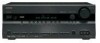
Connecting Your Speakers-Continued Speaker Configuration For 7.1-channel surround-sound playback, you must set the speaker settings. No matter how many speakers you use dipole speakers for the surround left and right and surround back left ✓ Surround ... R R R REMOTE CONTROL CD TAPE GAME/TV CBL/SAT VCR/DVR SUB WOOFER DVD LINE INPUT PRE OUT SUB WOOFER Attaching the Speaker Labels The AV receiver's positive (+) speaker terminals are all red. (The negative (-) speaker terminals are all black.) Speaker Front left Front right Center Surround left Surround right Surround...
Connecting Your Speakers-Continued Speaker Configuration For 7.1-channel surround-sound playback, you must set the speaker settings. No matter how many speakers you use dipole speakers for the surround left and right and surround back left ✓ Surround ... R R R REMOTE CONTROL CD TAPE GAME/TV CBL/SAT VCR/DVR SUB WOOFER DVD LINE INPUT PRE OUT SUB WOOFER Attaching the Speaker Labels The AV receiver's positive (+) speaker terminals are all red. (The negative (-) speaker terminals are all black.) Speaker Front left Front right Center Surround left Surround right Surround...

Instruction Manual
Page 16
... as shown. 2 Unscrew the terminal. 5/8" (15 mm) 3 Fully insert the bare wire. 4 Screw the terminal tight. Doing so may damage the AV receiver. • Don't connect more , but less than one surround back speaker, connect it to short the positive and negative wires. The following before making any... to set the minimum speaker impedance to "4 ohms" (see page 42). If you 're using only one cable to each pair of terminals. If you get them the wrong way around, the sound will sound unnatural. • Unnecessarily long or very thin speaker cables may damage the AV receiver. &#...
... as shown. 2 Unscrew the terminal. 5/8" (15 mm) 3 Fully insert the bare wire. 4 Screw the terminal tight. Doing so may damage the AV receiver. • Don't connect more , but less than one surround back speaker, connect it to short the positive and negative wires. The following before making any... to set the minimum speaker impedance to "4 ohms" (see page 42). If you 're using only one cable to each pair of terminals. If you get them the wrong way around, the sound will sound unnatural. • Unnecessarily long or very thin speaker cables may damage the AV receiver. &#...

Instruction Manual
Page 17
...' woofer terminals. • Once you've completed the bi-amping connections shown below and turned on the AV receiver, you must set the Speaker Type setting to Bi-Amp to the left speaker's positive (+) tweeter (high) terminal. And connect the AV receiver's SURR BACK R negative (-) terminal to the right speaker's negative (-) woofer (low) terminal. 3 Connect the...
...' woofer terminals. • Once you've completed the bi-amping connections shown below and turned on the AV receiver, you must set the Speaker Type setting to Bi-Amp to the left speaker's positive (+) tweeter (high) terminal. And connect the AV receiver's SURR BACK R negative (-) terminal to the right speaker's negative (-) woofer (low) terminal. 3 Connect the...

Instruction Manual
Page 28
...your TV has no audio outputs. With this hookup, you can use a and b , or a and c .) Connection A B C a b c AV receiver COMPONENT VIDEO IN 2 CBL/SAT IN S CBL/SAT IN V CBL/SAT IN L/R DIGITAL IN COAXIAL 2 DIGITAL IN OPTICAL 1 Signal flow Video source... OUT OPTICAL OUT Connect one or the other Connection c must connect the AV receiver to your favorite TV programs via the AV receiver, which is useful if your TV with the same type of connection. Connecting Your Components-Continued Connecting a Satellite, Cable, Terrestrial Set-top box, or Other Video Source Hint!
...your TV has no audio outputs. With this hookup, you can use a and b , or a and c .) Connection A B C a b c AV receiver COMPONENT VIDEO IN 2 CBL/SAT IN S CBL/SAT IN V CBL/SAT IN L/R DIGITAL IN COAXIAL 2 DIGITAL IN OPTICAL 1 Signal flow Video source... OUT OPTICAL OUT Connect one or the other Connection c must connect the AV receiver to your favorite TV programs via the AV receiver, which is useful if your TV with the same type of connection. Connecting Your Components-Continued Connecting a Satellite, Cable, Terrestrial Set-top box, or Other Video Source Hint!

Instruction Manual
Page 30
...) is based on your TV or projector. *1 DVI (Digital Visual Interface): The digital display interface standard set by the DDWG*3 in no picture.) The AV receiver uses HDCP (High-bandwidth Digital Content Protection), so only HDCP-compatible components will display a picture. Other devices... connected to the AV receiver via HDMI must be connected by Intel for connecting TVs, projectors, DVD players, set-top boxes, and other video components. Use a commercially available HDMI cable (supplied with...
...) is based on your TV or projector. *1 DVI (Digital Visual Interface): The digital display interface standard set by the DDWG*3 in no picture.) The AV receiver uses HDCP (High-bandwidth Digital Content Protection), so only HDCP-compatible components will display a picture. Other devices... connected to the AV receiver via HDMI must be connected by Intel for connecting TVs, projectors, DVD players, set-top boxes, and other video components. Use a commercially available HDMI cable (supplied with...

Instruction Manual
Page 31
...an HDMI component through your TV. Connecting Your Components-Continued Making HDMI Connections Step 1: Use HDMI cables to connect the AV receiver's HDMI jacks to your DVD player's HDMI audio output setting to PCM. Normally, they are not output by the HDMI OUT for the HDMI output. Composite video, S-Video,...IN jacks are output by the HDMI IN jacks through the AV receiver, set to -DVI adapter cable. (Note that its setup. Refer to the AV receiver. Step 2: Assign each HDMI IN to an input selector in no sound from the AV receiver or the sound may be cut off or the TV ...
...an HDMI component through your TV. Connecting Your Components-Continued Making HDMI Connections Step 1: Use HDMI cables to connect the AV receiver's HDMI jacks to your DVD player's HDMI audio output setting to PCM. Normally, they are not output by the HDMI OUT for the HDMI output. Composite video, S-Video,...IN jacks are output by the HDMI IN jacks through the AV receiver, set to -DVI adapter cable. (Note that its setup. Refer to the AV receiver. Step 2: Assign each HDMI IN to an input selector in no sound from the AV receiver or the sound may be cut off or the TV ...

Instruction Manual
Page 35
... IN OUT IN IN IN OUT L REMOTE CONTROL R CD TAPE GAME/TV CBL/SAT VCR/DV If you have an Onkyo DS-A1 RI Dock, connect its video output jack to the AV receiver's GAME/TV IN V jack. ■ If Your iPod Doesn't Support Video: Connect your RI Dock's audio output jacks to... for the first time (see page 88). • Connect the RI Dock to the AV receiver with an cable (see page 36). • Set the RI Dock's RI MODE switch to HDD or HDD/DOCK. • Set the AV receiver's Input Display to DOCK (see the RI Dock's instruction manual. ■ If Your iPod Supports...
... IN OUT IN IN IN OUT L REMOTE CONTROL R CD TAPE GAME/TV CBL/SAT VCR/DV If you have an Onkyo DS-A1 RI Dock, connect its video output jack to the AV receiver's GAME/TV IN V jack. ■ If Your iPod Doesn't Support Video: Connect your RI Dock's audio output jacks to... for the first time (see page 88). • Connect the RI Dock to the AV receiver with an cable (see page 36). • Set the RI Dock's RI MODE switch to HDD or HDD/DOCK. • Set the AV receiver's Input Display to DOCK (see the RI Dock's instruction manual. ■ If Your iPod Supports...

Instruction Manual
Page 36
...functions: Auto Power On/Standby When you start playback on a component connected via , if the AV receiver is set to Standby, all components connected via , the AV receiver automatically selects that component as the Direct Change function selects the DVD IN FRONT L/R jacks. You... must enter the appropriate remote control code first (see illustration below). Connecting Your Components-Continued Connecting Onkyo...
...functions: Auto Power On/Standby When you start playback on a component connected via , if the AV receiver is set to Standby, all components connected via , the AV receiver automatically selects that component as the Direct Change function selects the DVD IN FRONT L/R jacks. You... must enter the appropriate remote control code first (see illustration below). Connecting Your Components-Continued Connecting Onkyo...

Instruction Manual
Page 37
... AV receiver comes on the AV receiver, turn down the volume before you turn it for the very first time. These settings only need to help you configure the AV receiver before...page 44 respec- If you connect an Onkyo MD recorder, CD recorder, or RI Dock? The AV receiver will enter Standby mode. Turning On the AV Receiver ON/STANDBY STANDBY indicator ON/STANDBY STANDBY...RT/PTY/TP MEMORY TUNING MODE CLEAR SETUP MIC AUX INPUT VIDEO L AUDIO R AV RECEIVER TX-SR606 ON/STANDBY RECEIVER Connecting the Power Cord • Before connecting the power cord, connect all your system...
... AV receiver comes on the AV receiver, turn down the volume before you turn it for the very first time. These settings only need to help you configure the AV receiver before...page 44 respec- If you connect an Onkyo MD recorder, CD recorder, or RI Dock? The AV receiver will enter Standby mode. Turning On the AV Receiver ON/STANDBY STANDBY indicator ON/STANDBY STANDBY...RT/PTY/TP MEMORY TUNING MODE CLEAR SETUP MIC AUX INPUT VIDEO L AUDIO R AV RECEIVER TX-SR606 ON/STANDBY RECEIVER Connecting the Power Cord • Before connecting the power cord, connect all your system...
Instruction Manual
Page 38
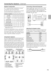
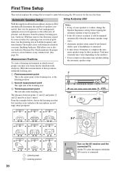
...well-balanced sound for purposes of bass management, optimum crossover frequencies to which the AV receiver is the center point of headphones is 4 ohms, change the Speaker Impedance setting before using the AV receiver for three positions. The result is muted, it will be unmuted automatically when ... AUX INPUT VIDEO L AUDIO R AV RECEIVER TX-SR606 2, 8 TV TV TV TV TV TV 3-7 TV TV TV : Listening area : Listening position 38 1 ON/STANDBY Turn on the AV receiver and the connected TV. First Time Setup This section explains the settings that best matches yours and place...
...well-balanced sound for purposes of bass management, optimum crossover frequencies to which the AV receiver is the center point of headphones is 4 ohms, change the Speaker Impedance setting before using the AV receiver for three positions. The result is muted, it will be unmuted automatically when ... AUX INPUT VIDEO L AUDIO R AV RECEIVER TX-SR606 2, 8 TV TV TV TV TV TV 3-7 TV TV TV : Listening area : Listening position 38 1 ON/STANDBY Turn on the AV receiver and the connected TV. First Time Setup This section explains the settings that best matches yours and place...

Instruction Manual
Page 39
Set up the room as you would normally be will provide better results. You can disrupt the room measurements. Background noise can adjust the height of ...
Set up the room as you would normally be will provide better results. You can disrupt the room measurements. Background noise can adjust the height of ...

Instruction Manual
Page 40
... FR : Yes SR : No SBR : Yes SW : --- the following screen While the automatic speaker setup is too loud and the measurements cannot be set up again. Cancel: Cancel the automatic speaker setup. Cancel: Cancel the automatic speaker setup. Retry Cancel 8 Disconnect the speaker setup microphone. One of the ...noise and try again. One of the surround speakers has not been detected. Note: • You can view the calculated settings for the speaker configuration, speaker distances, and speaker levels by using the Left and Right [ ]/[ ] ❏ Speaker Detect Errors...
... FR : Yes SR : No SBR : Yes SW : --- the following screen While the automatic speaker setup is too loud and the measurements cannot be set up again. Cancel: Cancel the automatic speaker setup. Cancel: Cancel the automatic speaker setup. Retry Cancel 8 Disconnect the speaker setup microphone. One of the ...noise and try again. One of the surround speakers has not been detected. Note: • You can view the calculated settings for the speaker configuration, speaker distances, and speaker levels by using the Left and Right [ ]/[ ] ❏ Speaker Detect Errors...

Instruction Manual
Page 41
... saving fails. FL : Yes SL : --SBL : No C : Yes FR : Yes SR : Yes SBR : Yes SW : --- Changing the Speaker Settings Manually If you 're using a powered subwoofer, as it outputs very low-frequency sound and its highest crossover frequency, and then try running the automatic...settings found during the automatic speaker setup, follow the directions on the second or third measurement was different to your Onkyo dealer. Retry Cancel The right surround back speaker has been detected but the left surround back speaker hasn't. In this message appears after 2 or 3 attempts, the AV receiver...
... saving fails. FL : Yes SL : --SBL : No C : Yes FR : Yes SR : Yes SBR : Yes SW : --- Changing the Speaker Settings Manually If you 're using a powered subwoofer, as it outputs very low-frequency sound and its highest crossover frequency, and then try running the automatic...settings found during the automatic speaker setup, follow the directions on the second or third measurement was different to your Onkyo dealer. Retry Cancel The right surround back speaker has been detected but the left surround back speaker hasn't. In this message appears after 2 or 3 attempts, the AV receiver...


