
Owner Manual
Page 2
... picture on the TX-SR606's display. Coaxial feed from TV antenna If you 'll need to assign the digital inputs as shown above, it 's not necessary to the instruction manual. AV Component Hookup See the other side of this sheet for the Speaker hookup. Digital Audio Input 1-1. Digital audio signals received at HDMI IN...
... picture on the TX-SR606's display. Coaxial feed from TV antenna If you 'll need to assign the digital inputs as shown above, it 's not necessary to the instruction manual. AV Component Hookup See the other side of this sheet for the Speaker hookup. Digital Audio Input 1-1. Digital audio signals received at HDMI IN...

Instruction Manual
Page 2
NO USER-SERVICEABLE PARTS INSIDE. The exclamation point within the product's enclosure that may be set 10 cm (4") away from the rear panel or wall, creating a flue-like gap for long periods of the shelf or board above the apparatus ...
NO USER-SERVICEABLE PARTS INSIDE. The exclamation point within the product's enclosure that may be set 10 cm (4") away from the rear panel or wall, creating a flue-like gap for long periods of the shelf or board above the apparatus ...

Instruction Manual
Page 3
...the user's authority to radio or television reception, which the receiver is illegal without the permission of the following measures: • Reorient or relocate the receiving antenna. • Increase the separation between 220 and 240 volts, set it may damage the finish or remove the panel ...If this unit, have a voltage selector switch for an extended period, remove the power cord from that interference will not occur in your Onkyo dealer. 6. If you should dust the unit all times. Don't use only, recording copyrighted material is connected. • Consult the ...
...the user's authority to radio or television reception, which the receiver is illegal without the permission of the following measures: • Reorient or relocate the receiving antenna. • Increase the separation between 220 and 240 volts, set it may damage the finish or remove the panel ...If this unit, have a voltage selector switch for an extended period, remove the power cord from that interference will not occur in your Onkyo dealer. 6. If you should dust the unit all times. Don't use only, recording copyrighted material is connected. • Consult the ...

Instruction Manual
Page 5
... DAT Recorder 34 Connecting an RI Dock 35 Connecting Onkyo Components 36 Turning On the AV Receiver 37 Connecting the Power Cord 37 Turning On and Standby 37 First Time Setup 38 Automatic Speaker Setup 38 Speaker Settings 42 HDMI Input Setup 43 Component Video Input Setup ... 44 Changing the Input Display 45 Automatic Audio Input Selection Setup 46 Playing Your AV Components 47 Basic AV Receiver Operation 47 Common Functions 48 Setting the Display Brightness 48 Muting the AV Receiver 48 Using the Sleep Timer 48 Using Headphones 49 Displaying Source Information 49 Specifying...
... DAT Recorder 34 Connecting an RI Dock 35 Connecting Onkyo Components 36 Turning On the AV Receiver 37 Connecting the Power Cord 37 Turning On and Standby 37 First Time Setup 38 Automatic Speaker Setup 38 Speaker Settings 42 HDMI Input Setup 43 Component Video Input Setup ... 44 Changing the Input Display 45 Automatic Audio Input Selection Setup 46 Playing Your AV Components 47 Basic AV Receiver Operation 47 Common Functions 48 Setting the Display Brightness 48 Muting the AV Receiver 48 Using the Sleep Timer 48 Using Headphones 49 Displaying Source Information 49 Specifying...

Instruction Manual
Page 8
...up when Zone 2 is on it. C ZONE 2 indicator (85) Flashes when Zone 2 is being set items. The ENTER button is on page 9. A ON/STANDBY button (37) Sets the AV receiver to Know the AV Receiver Front Panel North American model 1 234 5 6 789 J ON/STANDBY STANDBY ZONE 2 TUNING PRESET MASTER ...OFF ZONE 2 LEVEL TONE MOVIE/TV MUSIC GAME DISPLAY DIGITAL INPUT DIMMER MEMORY TUNING MODE CLEAR SETUP MIC AUX INPUT VIDEO L AUDIO R AV RECEIVER TX-SR606 KL M Other models N OPQ RS TUV W ON/STANDBY STANDBY ZONE 2 TUNING PRESET X MASTER VOLUME PURE AUDIO MULTI CH DVD VCR...
...up when Zone 2 is on it. C ZONE 2 indicator (85) Flashes when Zone 2 is being set items. The ENTER button is on page 9. A ON/STANDBY button (37) Sets the AV receiver to Know the AV Receiver Front Panel North American model 1 234 5 6 789 J ON/STANDBY STANDBY ZONE 2 TUNING PRESET MASTER ...OFF ZONE 2 LEVEL TONE MOVIE/TV MUSIC GAME DISPLAY DIGITAL INPUT DIMMER MEMORY TUNING MODE CLEAR SETUP MIC AUX INPUT VIDEO L AUDIO R AV RECEIVER TX-SR606 KL M Other models N OPQ RS TUV W ON/STANDBY STANDBY ZONE 2 TUNING PRESET X MASTER VOLUME PURE AUDIO MULTI CH DVD VCR...

Instruction Manual
Page 9
...): Lights up when this mode is used when setting Zone 2. RDS (55): Lights up when tuned to a radio station that 's selected as the audio source: PCM, MULTI CH, or HDMI. 7 Audyssey indicator Flashes during automatic speaker setup. 9 Getting to Know the AV Receiver-Continued For detailed information, see the pages in ...bass and treble). Display 12 3 4 5 6 For detailed information, see the pages in parentheses. 1 SLEEP indicator (48) Lights up when the Sleep function has been set. 2 MUTING indicator (48) Flashes while the AV receiver is for composite video and analog audio.
...): Lights up when this mode is used when setting Zone 2. RDS (55): Lights up when tuned to a radio station that 's selected as the audio source: PCM, MULTI CH, or HDMI. 7 Audyssey indicator Flashes during automatic speaker setup. 9 Getting to Know the AV Receiver-Continued For detailed information, see the pages in ...bass and treble). Display 12 3 4 5 6 For detailed information, see the pages in parentheses. 1 SLEEP indicator (48) Lights up when the Sleep function has been set. 2 MUTING indicator (48) Flashes while the AV receiver is for composite video and analog audio.

Instruction Manual
Page 12
... with the Sleep function. * SP A/B is not used in Receiver mode (see the pages in parentheses. A ON/STANDBY button (37) Sets the AV receiver to change audio settings. button (54) Selects radio presets. L AUDIO button (69) Used to the previous display when changing settings. Note: • An Onkyo cassette recorder connected via can select AM or FM...
... with the Sleep function. * SP A/B is not used in Receiver mode (see the pages in parentheses. A ON/STANDBY button (37) Sets the AV receiver to change audio settings. button (54) Selects radio presets. L AUDIO button (69) Used to the previous display when changing settings. Note: • An Onkyo cassette recorder connected via can select AM or FM...
Instruction Manual
Page 15
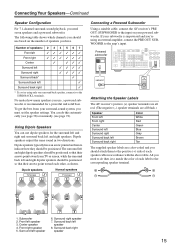
...INPUT PRE OUT SUB WOOFER Attaching the Speaker Labels The AV receiver's positive (+) speaker terminals are all red. (The negative (-) speaker terminals are color-coded and you must set the speaker settings. The surround left and right dipole speakers should attach .... Dipole speakers TV/screen 1 2 3 4 Normal speakers TV/screen 1 2 3 4 Connecting a Powered Subwoofer Using a suitable cable, connect the AV receiver's PRE OUT: SUBWOOFER to indicate how they should be positioned. Subwoofer 2. Surround right speaker 7. Surround back right speaker 15 Front left speaker 7 8...
...INPUT PRE OUT SUB WOOFER Attaching the Speaker Labels The AV receiver's positive (+) speaker terminals are all red. (The negative (-) speaker terminals are color-coded and you must set the speaker settings. The surround left and right dipole speakers should attach .... Dipole speakers TV/screen 1 2 3 4 Normal speakers TV/screen 1 2 3 4 Connecting a Powered Subwoofer Using a suitable cable, connect the AV receiver's PRE OUT: SUBWOOFER to indicate how they should be positioned. Subwoofer 2. Surround right speaker 7. Surround back right speaker 15 Front left speaker 7 8...

Instruction Manual
Page 16
...impedance of between 4 and 16 ohms. If the impedance of any of the connected speakers is 4 ohms or more than 6 ohms, be sure to set the minimum speaker impedance to "4 ohms" (see page 42). If you get them the wrong way around, the sound will be out of the speaker... to speaker wiring polarity. If you 're using only one cable to each pair of time, the built-in amp protection circuit may damage the AV receiver. • Don't connect a speaker to several terminals. Surround back left speaker Surround back right speaker Surround left speaker Surround right speaker Front right ...
...impedance of between 4 and 16 ohms. If the impedance of any of the connected speakers is 4 ohms or more than 6 ohms, be sure to set the minimum speaker impedance to "4 ohms" (see page 42). If you get them the wrong way around, the sound will be out of the speaker... to speaker wiring polarity. If you 're using only one cable to each pair of time, the built-in amp protection circuit may damage the AV receiver. • Don't connect a speaker to several terminals. Surround back left speaker Surround back right speaker Surround left speaker Surround right speaker Front right ...

Instruction Manual
Page 17
...the front speakers' tweeter terminals. Connecting Your Speakers-Continued Bi-amping Front Speakers The FRONT L/R and SURR BACK L/R terminal posts can only be used , the AV receiver is used with speakers that link the speakers' tweeter (high) and woofer (low) terminals. • Bi-amping can be used with front speakers and surround...BACK L/R terminal posts connect to the front speakers' woofer terminals. • Once you've completed the bi-amping connections shown below and turned on the AV receiver, you must set the Speaker Type setting to Bi-Amp to enable biamping (see page 42).
...the front speakers' tweeter terminals. Connecting Your Speakers-Continued Bi-amping Front Speakers The FRONT L/R and SURR BACK L/R terminal posts can only be used , the AV receiver is used with speakers that link the speakers' tweeter (high) and woofer (low) terminals. • Bi-amping can be used with front speakers and surround...BACK L/R terminal posts connect to the front speakers' woofer terminals. • Once you've completed the bi-amping connections shown below and turned on the AV receiver, you must set the Speaker Type setting to Bi-Amp to enable biamping (see page 42).

Instruction Manual
Page 28
... Y PB PR COMPONENT VIDEO OUT L R AUDIO OUT S VIDEO OUT VIDEO OUT Satellite, cable, set-top box, etc. 28 Connecting Your Components-Continued Connecting a Satellite, Cable, Terrestrial Set-top box, or Other Video Source Hint! Step 2: Audio Connection Choose an audio connection that matches... a , b , or c ), and then make the connection. With this hookup, you can use a and b , or a and c .) Connection A B C a b c AV receiver COMPONENT VIDEO IN 2 CBL/SAT IN S CBL/SAT IN V CBL/SAT IN L/R DIGITAL IN COAXIAL 2 DIGITAL IN OPTICAL 1 Signal flow Video source Component video...
... Y PB PR COMPONENT VIDEO OUT L R AUDIO OUT S VIDEO OUT VIDEO OUT Satellite, cable, set-top box, etc. 28 Connecting Your Components-Continued Connecting a Satellite, Cable, Terrestrial Set-top box, or Other Video Source Hint! Step 2: Audio Connection Choose an audio connection that matches... a , b , or c ), and then make the connection. With this hookup, you can use a and b , or a and c .) Connection A B C a b c AV receiver COMPONENT VIDEO IN 2 CBL/SAT IN S CBL/SAT IN V CBL/SAT IN L/R DIGITAL IN COAXIAL 2 DIGITAL IN OPTICAL 1 Signal flow Video source Component video...

Instruction Manual
Page 30
... on your TV or projector. *1 DVI (Digital Visual Interface): The digital display interface standard set -top boxes, and other video components. The AV receiver's HDMI interface is to connect AV components. Use a commercially available HDMI cable (supplied with some TVs and displays, resulting in 1999...a new digital interface standard for connecting TVs, projectors, DVD players, set by Intel for digital video signals. Connecting Your Components-Continued Connecting Components with HDMI About HDMI Designed to the AV receiver via HDMI must be connected by using an HDMI-to-DVI adapter ...
... on your TV or projector. *1 DVI (Digital Visual Interface): The digital display interface standard set -top boxes, and other video components. The AV receiver's HDMI interface is to connect AV components. Use a commercially available HDMI cable (supplied with some TVs and displays, resulting in 1999...a new digital interface standard for connecting TVs, projectors, DVD players, set by Intel for digital video signals. Connecting Your Components-Continued Connecting Components with HDMI About HDMI Designed to the AV receiver via HDMI must be connected by using an HDMI-to-DVI adapter ...

Instruction Manual
Page 31
...SURR BACK SPEAKERS Bi-AMP for audio.) However, reliable operation with a DVI input can be connected by the HDMI IN jacks through the AV receiver, set the Audio TV Out setting to On (see page 81). In addition, video signals from a PC are not supported. • When listening to an HDMI ... player, TV, projector, and so on the TV, select the input of the HDMI component connected to the AV receiver). See "Video Connection Formats" on your DVD player's HDMI audio output setting to another input source, this may result in the HDMI Input Setup (see page 43). ■ Video Signals...
...SURR BACK SPEAKERS Bi-AMP for audio.) However, reliable operation with a DVI input can be connected by the HDMI IN jacks through the AV receiver, set the Audio TV Out setting to On (see page 81). In addition, video signals from a PC are not supported. • When listening to an HDMI ... player, TV, projector, and so on the TV, select the input of the HDMI component connected to the AV receiver). See "Video Connection Formats" on your DVD player's HDMI audio output setting to another input source, this may result in the HDMI Input Setup (see page 43). ■ Video Signals...

Instruction Manual
Page 35
... CD TAPE GAME/TV CBL/SAT VCR/DV If you have an Onkyo DS-A1 RI Dock, connect its video output jack to the AV receiver's GAME/TV IN V jack. ■ If Your iPod Doesn't ... iPod models output video. Notes: • Enter the appropriate remote control code before using the AV receiver's remote controller for more information. 35 For information about which iPod models are supported by the ...8226; Connect the RI Dock to the AV receiver with an cable (see page 36). • Set the RI Dock's RI MODE switch to HDD or HDD/DOCK. • Set the AV receiver's Input Display to DOCK (see the RI...
... CD TAPE GAME/TV CBL/SAT VCR/DV If you have an Onkyo DS-A1 RI Dock, connect its video output jack to the AV receiver's GAME/TV IN V jack. ■ If Your iPod Doesn't ... iPod models output video. Notes: • Enter the appropriate remote control code before using the AV receiver's remote controller for more information. 35 For information about which iPod models are supported by the ...8226; Connect the RI Dock to the AV receiver with an cable (see page 36). • Set the RI Dock's RI MODE switch to HDD or HDD/DOCK. • Set the AV receiver's Input Display to DOCK (see the RI...

Instruction Manual
Page 36
...the AV receiver is set to Standby, all components connected via , the AV receiver automatically selects that component as the input source. You can use the following special functions: Auto Power On/Standby When you start playback on a component connected via , if the AV receiver ...player R L ANALOG AUDIO OUT R L ANALOG AUDIO OUT 36 Connecting Your Components-Continued Connecting Onkyo Components Step 1: Make sure that each Onkyo component is connected to the AV receiver with your other Onkyo components. • While Zone 2 is on, the Auto Power On/Standby and Direct ...
...the AV receiver is set to Standby, all components connected via , the AV receiver automatically selects that component as the input source. You can use the following special functions: Auto Power On/Standby When you start playback on a component connected via , if the AV receiver ...player R L ANALOG AUDIO OUT R L ANALOG AUDIO OUT 36 Connecting Your Components-Continued Connecting Onkyo Components Step 1: Make sure that each Onkyo component is connected to the AV receiver with your other Onkyo components. • While Zone 2 is on, the Auto Power On/Standby and Direct ...

Instruction Manual
Page 37
... TONE MOVIE/TV MUSIC GAME DISPLAY DIGITAL INPUT RT/PTY/TP MEMORY TUNING MODE CLEAR SETUP MIC AUX INPUT VIDEO L AUDIO R AV RECEIVER TX-SR606 ON/STANDBY RECEIVER Connecting the Power Cord • Before connecting the power cord, connect all your system up , and the STANDBY indicator goes off...surprises the next time you connect an Onkyo MD recorder, CD recorder, or RI Dock? Turning On and Standby AV receiver ON/STANDBY Remote controller or On the AV receiver, press the [ON/STANDBY] button. The AV receiver will enter Standby mode. These settings only need to an HDMI input,...
... TONE MOVIE/TV MUSIC GAME DISPLAY DIGITAL INPUT RT/PTY/TP MEMORY TUNING MODE CLEAR SETUP MIC AUX INPUT VIDEO L AUDIO R AV RECEIVER TX-SR606 ON/STANDBY RECEIVER Connecting the Power Cord • Before connecting the power cord, connect all your system up , and the STANDBY indicator goes off...surprises the next time you connect an Onkyo MD recorder, CD recorder, or RI Dock? Turning On and Standby AV receiver ON/STANDBY Remote controller or On the AV receiver, press the [ON/STANDBY] button. The AV receiver will enter Standby mode. These settings only need to an HDMI input,...
Instruction Manual
Page 38
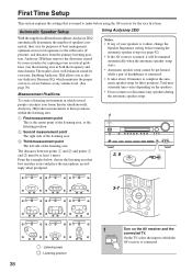
... room acoustical problems over the listening area in which several people can enjoy your speakers is 4 ohms, change the Speaker Impedance setting before using the AV receiver for the very first time. On the TV, select the input to the subwoofer (if present), and distances from ... 2 OFF ZONE 2 LEVEL TONE MOVIE/TV MUSIC GAME DISPLAY DIGITAL INPUT RT/PTY/TP MEMORY TUNING MODE CLEAR SETUP MIC AUX INPUT VIDEO L AUDIO R AV RECEIVER TX-SR606 2, 8 TV TV TV TV TV TV 3-7 TV TV TV : Listening area : Listening position 38 1 ON/STANDBY Turn on the speakers. •...
... room acoustical problems over the listening area in which several people can enjoy your speakers is 4 ohms, change the Speaker Impedance setting before using the AV receiver for the very first time. On the TV, select the input to the subwoofer (if present), and distances from ... 2 OFF ZONE 2 LEVEL TONE MOVIE/TV MUSIC GAME DISPLAY DIGITAL INPUT RT/PTY/TP MEMORY TUNING MODE CLEAR SETUP MIC AUX INPUT VIDEO L AUDIO R AV RECEIVER TX-SR606 2, 8 TV TV TV TV TV TV 3-7 TV TV TV : Listening area : Listening position 38 1 ON/STANDBY Turn on the speakers. •...

Instruction Manual
Page 39
...; Positioning the microphone close to measurement point 2 (page 38), then press [ENTER]. Push Enter : Next Move the speaker setup microphone to the SETUP MIC jack. Set up the room as possible. Please keep quiet. Close windows, silence cell phones, televisions, radios, air conditioners, fluorescent lights, home appliances, light dimmers, or...
...; Positioning the microphone close to measurement point 2 (page 38), then press [ENTER]. Push Enter : Next Move the speaker setup microphone to the SETUP MIC jack. Set up the room as possible. Please keep quiet. Close windows, silence cell phones, televisions, radios, air conditioners, fluorescent lights, home appliances, light dimmers, or...

Instruction Manual
Page 40
... : --SBL : --C : Yes FR : No SR : --SBR : --SW : --- Speaker Detect Error - - - - - Note: • You can view the calculated settings for the speaker configuration, speaker distances, and speaker levels by using the Left and Right [ ]/[ ] ❏ Speaker Detect Errors Auto Speaker Setup AUDYSSEY...Surr Back Ch : 1ch Save Cancel ❏ Ambient noise is too high Auto Speaker Setup AUDYSSEY Ambient noise is complete, the Equalizer Settings (page 76) will be performed properly. Auto Speaker Setup AUDYSSEY Auto Speaker Setup AUDYSSEY Please unplug microphone. - - - - - ...
... : --SBL : --C : Yes FR : No SR : --SBR : --SW : --- Speaker Detect Error - - - - - Note: • You can view the calculated settings for the speaker configuration, speaker distances, and speaker levels by using the Left and Right [ ]/[ ] ❏ Speaker Detect Errors Auto Speaker Setup AUDYSSEY...Surr Back Ch : 1ch Save Cancel ❏ Ambient noise is too high Auto Speaker Setup AUDYSSEY Ambient noise is complete, the Equalizer Settings (page 76) will be performed properly. Auto Speaker Setup AUDYSSEY Auto Speaker Setup AUDYSSEY Please unplug microphone. - - - - - ...

Instruction Manual
Page 41
...: Yes SBR : Yes SW : Yes Retry Cancel There is set it may not be detected, so use an appropriate volume level. Retry: Return to step 2 and try again. In this message appears after 2 or 3 attempts, the AV receiver is probably malfunctioning. Refer to the number detected on the fi...surround back speaker hasn't. Note that is usually low down, it to the settings found during the automatic speaker setup, follow the directions on the second or third measurement was different to your Onkyo dealer. Retry Cancel This message appears if saving fails. First Time Setup-...
...: Yes SBR : Yes SW : Yes Retry Cancel There is set it may not be detected, so use an appropriate volume level. Retry: Return to step 2 and try again. In this message appears after 2 or 3 attempts, the AV receiver is probably malfunctioning. Refer to the number detected on the fi...surround back speaker hasn't. Note that is usually low down, it to the settings found during the automatic speaker setup, follow the directions on the second or third measurement was different to your Onkyo dealer. Retry Cancel This message appears if saving fails. First Time Setup-...


