
Owner Manual
Page 1
Contents Introduction 2 Connection 15 Turning On & First Time Setup .....37 Basic Operations 50 Using the Listening Modes ........59 Advanced Setup 66 Zone 2 82 Controlling Other Components ....86 Others 97 En Please retain this manual will enable you for future reference. Following the instructions in the unit. AV Receiver HT-RC160 Instruction Manual Thank you to obtain optimum performance and listening enjoyment from your new AV Receiver. Please read this manual thoroughly before making connections and plugging in this manual for purchasing an Onkyo AV Receiver.
Contents Introduction 2 Connection 15 Turning On & First Time Setup .....37 Basic Operations 50 Using the Listening Modes ........59 Advanced Setup 66 Zone 2 82 Controlling Other Components ....86 Others 97 En Please retain this manual will enable you for future reference. Following the instructions in the unit. AV Receiver HT-RC160 Instruction Manual Thank you to obtain optimum performance and listening enjoyment from your new AV Receiver. Please read this manual thoroughly before making connections and plugging in this manual for purchasing an Onkyo AV Receiver.
Owner Manual
Page 3
... of the following measures: • Reorient or relocate the receiving antenna. • Increase the separation between the equipment and receiver. • Connect the equipment into an outlet on the unit's rear panel (e.g., AC 230 V, 50 Hz or AC 120 V, 60 Hz). AC outlet voltages... any other chemical solvents, because they may leave marks on the unit, contact your Onkyo dealer. 8. models FCC Information for User CAUTION: The user changes or modifications not expressly approved by your Onkyo dealer. 3. For Canadian Models NOTE: THIS CLASS B DIGITAL APPARATUS COMPLIES WITH CANADIAN...
... of the following measures: • Reorient or relocate the receiving antenna. • Increase the separation between the equipment and receiver. • Connect the equipment into an outlet on the unit's rear panel (e.g., AC 230 V, 50 Hz or AC 120 V, 60 Hz). AC outlet voltages... any other chemical solvents, because they may leave marks on the unit, contact your Onkyo dealer. 8. models FCC Information for User CAUTION: The user changes or modifications not expressly approved by your Onkyo dealer. 3. For Canadian Models NOTE: THIS CLASS B DIGITAL APPARATUS COMPLIES WITH CANADIAN...

Owner Manual
Page 5
...Connecting a Game Console 31 Connecting a Camcorder or Other Device .......... 32 Connecting a Portable Audio player 32 Connecting a CD Player or Turntable 33 Connecting a Cassette, CDR, MiniDisc, or DAT Recorder 34 Connecting an RI Dock 35 Connecting a Dock with the Universal Port connector ... 35 Connecting Onkyo V Components 36 Connecting... Codes 86 Looking up for Remote Control Code 86 Entering Remote Control Codes 88 Remote Control Codes for Onkyo Components Connected via V 89 Resetting REMOTE MODE Buttons 89 Resetting the Remote Controller 89 Controlling a TV 90 Controlling ...
...Connecting a Game Console 31 Connecting a Camcorder or Other Device .......... 32 Connecting a Portable Audio player 32 Connecting a CD Player or Turntable 33 Connecting a Cassette, CDR, MiniDisc, or DAT Recorder 34 Connecting an RI Dock 35 Connecting a Dock with the Universal Port connector ... 35 Connecting Onkyo V Components 36 Connecting... Codes 86 Looking up for Remote Control Code 86 Entering Remote Control Codes 88 Remote Control Codes for Onkyo Components Connected via V 89 Resetting REMOTE MODE Buttons 89 Resetting the Remote Controller 89 Controlling a TV 90 Controlling ...
Owner Manual
Page 6
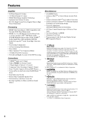
...Music Optimizer*3 for Compressed Music • 192 kHz/24-bit D/A Converters • Powerful and Highly Accurate 32-bit DSP Processing Connections • 5 HDMI*4 Inputs and 1 Output • Onkyo for System Control • 4 Digital Inputs (2 Optical / 2 Coaxial) • Component Video Switching (2 Inputs/1 Output) &#...and High Definition Multimedia Interface are proprietary trademarks of iBiquity Digital Corporation. To receive HD Radio broadcasts, you must install an Onkyo UP-HT1 HD Radio tuner module (sold separately). *6. U.S. HD Radio™ and the HD Radio Ready logo are...
...Music Optimizer*3 for Compressed Music • 192 kHz/24-bit D/A Converters • Powerful and Highly Accurate 32-bit DSP Processing Connections • 5 HDMI*4 Inputs and 1 Output • Onkyo for System Control • 4 Digital Inputs (2 Optical / 2 Coaxial) • Component Video Switching (2 Inputs/1 Output) &#...and High Definition Multimedia Interface are proprietary trademarks of iBiquity Digital Corporation. To receive HD Radio broadcasts, you must install an Onkyo UP-HT1 HD Radio tuner module (sold separately). *6. U.S. HD Radio™ and the HD Radio Ready logo are...
Owner Manual
Page 8
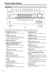
... buttons (84) The [ZONE 2] button is used to display various information about the currently selected input source. TONE button (51) Used to turn on the connected TV. Q RETURN button This button is used to turn off the output of Zone 2. [-] & [+] buttons (51, 85) Used to access the onscreen setup menus that...
... buttons (84) The [ZONE 2] button is used to display various information about the currently selected input source. TONE button (51) Used to turn on the connected TV. Q RETURN button This button is used to turn off the output of Zone 2. [-] & [+] buttons (51, 85) Used to access the onscreen setup menus that...

Owner Manual
Page 9
... mode is muted. S PHONES jack (52) This 1/4-inch phone jack is selected. E Tuning indicators (53) AUTO (53): Lights up when tuned to connect a camcorder, game console, and so on. F Message area Displays various information. Display U AUX INPUT (32) This input can be used to a stereo... Speaker Setup. BC D E F G H For detailed information, see the pages in parentheses. T Input selector buttons (50) These buttons are jacks for connecting a standard pair of the AV receiver to Min, 1 through 79 or Max. V SETUP MIC jack (46) The Audyssey 2EQ™ Room Correction and Speaker...
... mode is muted. S PHONES jack (52) This 1/4-inch phone jack is selected. E Tuning indicators (53) AUTO (53): Lights up when tuned to connect a camcorder, game console, and so on. F Message area Displays various information. Display U AUX INPUT (32) This input can be used to a stereo... Speaker Setup. BC D E F G H For detailed information, see the pages in parentheses. T Input selector buttons (50) These buttons are jacks for connecting a standard pair of the AV receiver to Min, 1 through 79 or Max. V SETUP MIC jack (46) The Audyssey 2EQ™ Room Correction and Speaker...

Owner Manual
Page 10
...composite video jack should be used to suit your setup. J FRONT L/R, CENTER, SURR L/R, and SURR BACK L/R speakers These terminal posts are for connecting components with front speakers and surround back speakers respectively, or used with an HDMI output, such as CD and DVD/BD players. K V REMOTE CONTROL.../BD recorder, or DVR (digital video recorder). See "Digital Input Setup" on another Onkyo AV component. See "Bi-amping the Front Speakers" on page 42. The AV receiver's remote controller can be connected to bi-amp the front speakers. C DIGITAL IN OPTICAL 1 and 2 These optical ...
...composite video jack should be used to suit your setup. J FRONT L/R, CENTER, SURR L/R, and SURR BACK L/R speakers These terminal posts are for connecting components with front speakers and surround back speakers respectively, or used with an HDMI output, such as CD and DVD/BD players. K V REMOTE CONTROL.../BD recorder, or DVR (digital video recorder). See "Digital Input Setup" on another Onkyo AV component. See "Bi-amping the Front Speakers" on page 42. The AV receiver's remote controller can be connected to bi-amp the front speakers. C DIGITAL IN OPTICAL 1 and 2 These optical ...
Owner Manual
Page 11
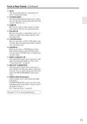
... video and analog audio. You can be used to a line input on an integrated amplifier in Zone 2. The FRONT HIGH L/R terminal can be connected to connect the speakers in Zone 2. Front & Rear Panels-Continued L CD IN This analog audio input is output from each jack. O CBL/SAT IN ...Here you can connect a cable/satellite receiver, settop box, etc. Q DVD/BD IN Here you can connect a DVD/BD player. Input jacks include composite video and analog audio. S PRE OUT: SUBWOOFER This analog audio...
... video and analog audio. You can be used to a line input on an integrated amplifier in Zone 2. The FRONT HIGH L/R terminal can be connected to connect the speakers in Zone 2. Front & Rear Panels-Continued L CD IN This analog audio input is output from each jack. O CBL/SAT IN ...Here you can connect a cable/satellite receiver, settop box, etc. Q DVD/BD IN Here you can connect a DVD/BD player. Input jacks include composite video and analog audio. S PRE OUT: SUBWOOFER This analog audio...

Owner Manual
Page 12
...fluorescent lights. troller, because the buttons may not work reliably if the AV receiver is installed in a rack behind colored glass doors. nent connected via HDMI (pages 90, 91), point the remote controller at the AV receiver's remote control sensor, as possible to bright light, such as... the polarity diagram inside the battery compartment. 3 Replace the cover and push it . • When you want to operate an Onkyo component without V connection, point the remote controller at the other component to use the remote controller for a long time, remove the batteries to use it...
...fluorescent lights. troller, because the buttons may not work reliably if the AV receiver is installed in a rack behind colored glass doors. nent connected via HDMI (pages 90, 91), point the remote controller at the AV receiver's remote control sensor, as possible to bright light, such as... the polarity diagram inside the battery compartment. 3 Replace the cover and push it . • When you want to operate an Onkyo component without V connection, point the remote controller at the other component to use the remote controller for a long time, remove the batteries to use it...

Owner Manual
Page 13
.... button (54) Used to select radio presets. 5 Number buttons (53) Used to control your DVD/BD player, CD player, and other components. Note: An Onkyo cassette recorder connected via V can select a preset directly. You can select AM or FM by pressing the [TUNER] button repeatedly. 1 Arrow [R]/[X] buttons Used to select the listening...
.... button (54) Used to select radio presets. 5 Number buttons (53) Used to control your DVD/BD player, CD player, and other components. Note: An Onkyo cassette recorder connected via V can select a preset directly. You can select AM or FM by pressing the [TUNER] button repeatedly. 1 Arrow [R]/[X] buttons Used to select the listening...

Owner Manual
Page 14
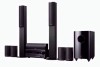
... are used mainly for your own home-just like being in a front corner, or at the same time. With analog or digital TV, you can connect the powered subwoofer with good bass, experiment by installing the subwoofer in a movie theater or concert hall. Position them inward so as possible). Position them... movies it is to enjoy Dolby Pro Logic IIz Height, etc. In general, a good bass sound can enjoy Dolby Pro Logic IIx, DTS Neo:6, or Onkyo's original DSP listening modes.
... are used mainly for your own home-just like being in a front corner, or at the same time. With analog or digital TV, you can connect the powered subwoofer with good bass, experiment by installing the subwoofer in a movie theater or concert hall. Position them inward so as possible). Position them... movies it is to enjoy Dolby Pro Logic IIz Height, etc. In general, a good bass sound can enjoy Dolby Pro Logic IIx, DTS Neo:6, or Onkyo's original DSP listening modes.

Owner Manual
Page 15
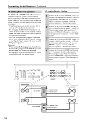
...to indicate how they should be positioned. Dipole speakers output the same sound in accordance with the HT-S7200 Home Theater System. • If you are using only one surround back speaker, connect it to the SURR BACK L terminals. To get the best from your surround sound system, you... before inserting the banana plug. • Do not insert the speaker code directly into the center hole of the speaker terminal. Connecting the AV Receiver Connecting Your Speakers Speaker Configuration For 7.1-channel surround-sound playback, you need to set the speaker settings.
...to indicate how they should be positioned. Dipole speakers output the same sound in accordance with the HT-S7200 Home Theater System. • If you are using only one surround back speaker, connect it to the SURR BACK L terminals. To get the best from your surround sound system, you... before inserting the banana plug. • Do not insert the speaker code directly into the center hole of the speaker terminal. Connecting the AV Receiver Connecting Your Speakers Speaker Configuration For 7.1-channel surround-sound playback, you need to set the speaker settings.
Owner Manual
Page 16
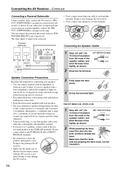
...; If you use speakers with the AV receiver's rear panel. Doing so may damage the AV receiver. 16 • Don't connect more than one speaker to several terminals. Connecting the Speaker Cables 1 Strip 1/2"-5/8" (12- 1/2"-5/8"(12-15 mm) 15 mm) of insulation from the ends of the two surround... quality and should be out of the wire does not have contact with a lower impedance, and use 4 or 5 speakers, connect each jack. You can connect speakers with two SUBWOOFER PREOUT jacks respectively. Make sure that the terminals are gripping the bare wires, not the insulation. If you...
...; If you use speakers with the AV receiver's rear panel. Doing so may damage the AV receiver. 16 • Don't connect more than one speaker to several terminals. Connecting the Speaker Cables 1 Strip 1/2"-5/8" (12- 1/2"-5/8"(12-15 mm) 15 mm) of insulation from the ends of the two surround... quality and should be out of the wire does not have contact with a lower impedance, and use 4 or 5 speakers, connect each jack. You can connect speakers with two SUBWOOFER PREOUT jacks respectively. Make sure that the terminals are gripping the bare wires, not the insulation. If you...
Owner Manual
Page 17
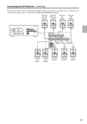
If you're using only one surround back speaker, connect it to each pair of terminals. Surround back left speaker Surround back right speaker Surround left speaker Surround right speaker Front high left speaker Front high right speaker Front left (L) SURR BACK SPEAKERS terminals. Connecting the AV Receiver-Continued The following illustration shows which speaker should be connected to the left speaker Front right speaker Center speaker 17
If you're using only one surround back speaker, connect it to each pair of terminals. Surround back left speaker Surround back right speaker Surround left speaker Surround right speaker Front high left speaker Front high right speaker Front left (L) SURR BACK SPEAKERS terminals. Connecting the AV Receiver-Continued The following illustration shows which speaker should be connected to the left speaker Front right speaker Center speaker 17
Owner Manual
Page 18
...turned on the AV receiver, you must set the "Speaker Type" setting to "Bi-Amp" to the left speaker's positive (+) Woofer (low) terminal. And connect the AV receiver's FRONT L negative (-) terminal to the left speaker's negative (-) Tweeter (high) terminal. 18 FRONT SPEAKERS L L Left speaker Tweeter (high)... (+) Woofer (low) terminal. nect to 5.1 speakers in the main room. • For bi-amping, the FRONT L/R terminal posts con- Connecting the AV Receiver-Continued Bi-amping the Front Speakers The FRONT L/R and SURR BACK L/R terminal posts can only be used , the AV receiver ...
...turned on the AV receiver, you must set the "Speaker Type" setting to "Bi-Amp" to the left speaker's positive (+) Woofer (low) terminal. And connect the AV receiver's FRONT L negative (-) terminal to the left speaker's negative (-) Tweeter (high) terminal. 18 FRONT SPEAKERS L L Left speaker Tweeter (high)... (+) Woofer (low) terminal. nect to 5.1 speakers in the main room. • For bi-amping, the FRONT L/R terminal posts con- Connecting the AV Receiver-Continued Bi-amping the Front Speakers The FRONT L/R and SURR BACK L/R terminal posts can only be used , the AV receiver ...
Owner Manual
Page 19
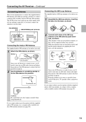
...antenna, try a commercially available outdoor FM antenna instead (see page 20). The AV Receiver won't pick up any radio signals without any antenna connected, so you must connect the antenna to use only. 1 Assemble the AM loop antenna, inserting the tabs into the base, as possible from your AV Receiver is...position of the AM antenna to the AM antenna push terminals, as shown. (The antenna's wires are not polarity sensitive, so they can be connected either way around.) Make sure that the wires are attached securely and that you 'll need to tune into the jack. If you cannot achieve...
...antenna, try a commercially available outdoor FM antenna instead (see page 20). The AV Receiver won't pick up any radio signals without any antenna connected, so you must connect the antenna to use only. 1 Assemble the AM loop antenna, inserting the tabs into the base, as possible from your AV Receiver is...position of the AM antenna to the AM antenna push terminals, as shown. (The antenna's wires are not polarity sensitive, so they can be connected either way around.) Make sure that the wires are attached securely and that you 'll need to tune into the jack. If you cannot achieve...

Owner Manual
Page 20
...located away from possible noise sources, such as neon signs, busy roads, etc. • For safety reasons, outdoor antenna should be left connected. TV/FM antenna splitter To AV Receiver To TV (or VCR) 20 Note that the AM loop antenna should be situated well away from... power lines and other high-voltage equipment. • Outdoor antenna must be obtained indoors by mounting horizontally above a window. Connecting an Outdoor AM Antenna If good reception cannot be used in accordance with the supplied indoor FM antenna, try a commercially available outdoor FM antenna...
...located away from possible noise sources, such as neon signs, busy roads, etc. • For safety reasons, outdoor antenna should be left connected. TV/FM antenna splitter To AV Receiver To TV (or VCR) 20 Note that the AM loop antenna should be situated well away from... power lines and other high-voltage equipment. • Outdoor antenna must be obtained indoors by mounting horizontally above a window. Connecting an Outdoor AM Antenna If good reception cannot be used in accordance with the supplied indoor FM antenna, try a commercially available outdoor FM antenna...

Owner Manual
Page 21
...(RCA) Stereo mini plug cable The AV receiver does not support SCART plugs. Wrong! Jack HDMI V OPTICAL L R Description HDMI connections can cause noise or malfunctions). • To prevent interference, keep audio and video cables away from power cords and speaker cables. The...-definition digital video and audio and offer the best picture and sound quality. This cable carries analog audio. Use red plugs to connect left-channel audio inputs and outputs (typically labeled "L"). Right! Component video separates the luminance (Y) and color difference signals (PR, PB...
...(RCA) Stereo mini plug cable The AV receiver does not support SCART plugs. Wrong! Jack HDMI V OPTICAL L R Description HDMI connections can cause noise or malfunctions). • To prevent interference, keep audio and video cables away from power cords and speaker cables. The...-definition digital video and audio and offer the best picture and sound quality. This cable carries analog audio. Use red plugs to connect left-channel audio inputs and outputs (typically labeled "L"). Right! Component video separates the luminance (Y) and color difference signals (PR, PB...

Owner Manual
Page 22
...have been required to eight channels of the HDMI standard. With HDMI, a single cable can display the picture. Note: Do not connect the -compatible component more than -compatible components cannot be used with CEC (Consumer Electronics Control), which stands for Remote Interactive over HDMI... set -top boxes, and other than the above audio formats. ■ Onkyo for System Control , which allows system control over HDMI, is the name of the above -mentioned is up to connect AV components. Do not connect the AV receiver to "On" (page 79). • See "Controlling ...
...have been required to eight channels of the HDMI standard. With HDMI, a single cable can display the picture. Note: Do not connect the -compatible component more than -compatible components cannot be used with CEC (Consumer Electronics Control), which stands for Remote Interactive over HDMI... set -top boxes, and other than the above audio formats. ■ Onkyo for System Control , which allows system control over HDMI, is the name of the above -mentioned is up to connect AV components. Do not connect the AV receiver to "On" (page 79). • See "Controlling ...
Owner Manual
Page 23
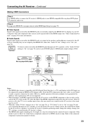
... speakers. Composite video and component video sources can be seen on the TV screen (on the TV, select the input of the HDMI component connected to the AV receiver). To stop the AV receiver's speakers producing sound, change the settings, change your TV's speakers, set the "Audio ..., if you turn down the AV receiver's volume. • The HDMI audio signal (sampling rate, bit length, etc.) may be connected by the connected source component. See "Video Connection Formats" on . HDMI OUT HDMI IN TV Blu-ray player/DVD player HDMI IN 1 (DVD/BD) HDMI Notes: • The...
... speakers. Composite video and component video sources can be seen on the TV screen (on the TV, select the input of the HDMI component connected to the AV receiver). To stop the AV receiver's speakers producing sound, change the settings, change your TV's speakers, set the "Audio ..., if you turn down the AV receiver's volume. • The HDMI audio signal (sampling rate, bit length, etc.) may be connected by the connected source component. See "Video Connection Formats" on . HDMI OUT HDMI IN TV Blu-ray player/DVD player HDMI IN 1 (DVD/BD) HDMI Notes: • The...


