
Owner Manual
Page 1
Contents Introduction 2 Connection 15 Turning On & First Time Setup .....37 Basic Operations 50 Using the Listening Modes ........59 Advanced Setup 66 Zone 2 82 Controlling Other Components ....86 Others 97 En AV Receiver HT-RC160 Instruction Manual Thank you to obtain optimum performance and listening enjoyment from your new AV Receiver. Following the instructions in the unit. Please read this manual for purchasing an Onkyo AV Receiver. Please retain this manual thoroughly before making connections and plugging in this manual will enable you for future reference.
Contents Introduction 2 Connection 15 Turning On & First Time Setup .....37 Basic Operations 50 Using the Listening Modes ........59 Advanced Setup 66 Zone 2 82 Controlling Other Components ....86 Others 97 En AV Receiver HT-RC160 Instruction Manual Thank you to obtain optimum performance and listening enjoyment from your new AV Receiver. Following the instructions in the unit. Please read this manual for purchasing an Onkyo AV Receiver. Please retain this manual thoroughly before making connections and plugging in this manual will enable you for future reference.
Owner Manual
Page 3
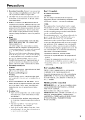
...Wet Hands-Never handle this Unit with a weak solution of the following measures: • Reorient or relocate the receiving antenna. • Increase the separation between the equipment and receiver. • Connect the equipment into an outlet on , the user is connected. • Consult the dealer ...8226; Do not leave rubber or plastic items on the unit, contact your Onkyo dealer. 8. AC Fuse-The AC fuse inside this equipment does cause harmful interference to radio or television reception, which the receiver is encouraged to try to Part 15 of the copyright holder. 2. For stubborn...
...Wet Hands-Never handle this Unit with a weak solution of the following measures: • Reorient or relocate the receiving antenna. • Increase the separation between the equipment and receiver. • Connect the equipment into an outlet on , the user is connected. • Consult the dealer ...8226; Do not leave rubber or plastic items on the unit, contact your Onkyo dealer. 8. AC Fuse-The AC fuse inside this equipment does cause harmful interference to radio or television reception, which the receiver is encouraged to try to Part 15 of the copyright holder. 2. For stubborn...

Owner Manual
Page 5
...an RI Dock 35 Connecting a Dock with the Universal Port connector ... 35 Connecting Onkyo V Components 36 Connecting the Power Cord 36 Turning On & First Time Setup Turning On the AV Receiver 37 Turning On and Standby 37 First Time Setup 38 Using the Onscreen Setup ...89 Controlling a TV 90 Controlling a DVD/BD Player, or DVD/BD Recorder ... 91 Controlling a VCR or PVR 92 Controlling a Satellite Receiver or Cable Receiver ... 93 Controlling a CD Player 94 Controlling an RI Dock 95 Controlling a Cassette Recorder 96 Others Troubleshooting 97 Specifications 101 Video Resolution Chart ...
...an RI Dock 35 Connecting a Dock with the Universal Port connector ... 35 Connecting Onkyo V Components 36 Connecting the Power Cord 36 Turning On & First Time Setup Turning On the AV Receiver 37 Turning On and Standby 37 First Time Setup 38 Using the Onscreen Setup ...89 Controlling a TV 90 Controlling a DVD/BD Player, or DVD/BD Recorder ... 91 Controlling a VCR or PVR 92 Controlling a Satellite Receiver or Cable Receiver ... 93 Controlling a CD Player 94 Controlling an RI Dock 95 Controlling a Cassette Recorder 96 Others Troubleshooting 97 Specifications 101 Video Resolution Chart ...
Owner Manual
Page 6
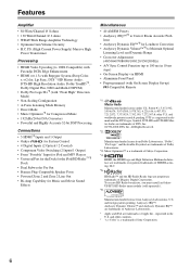
... 192 kHz/24-bit D/A Converters • Powerful and Highly Accurate 32-bit DSP Processing Connections • 5 HDMI*4 Inputs and 1 Output • Onkyo for System Control • 4 Digital Inputs (2 Optical / 2 Coaxial) • Component Video Switching (2 Inputs/1 Output) • Front "Portable" ... DTS-HD and DTS-HD Master Audio are trademarks of Onkyo Corporation. *4. Manufactured under U.S. and foreign patents pending. DTS is a trademark of Dolby Laboratories. *3. To receive HD Radio broadcasts, you must install an Onkyo UP-HT1 HD Radio tuner module (sold separately). *6....
... 192 kHz/24-bit D/A Converters • Powerful and Highly Accurate 32-bit DSP Processing Connections • 5 HDMI*4 Inputs and 1 Output • Onkyo for System Control • 4 Digital Inputs (2 Optical / 2 Coaxial) • Component Video Switching (2 Inputs/1 Output) • Front "Portable" ... DTS-HD and DTS-HD Master Audio are trademarks of Onkyo Corporation. *4. Manufactured under U.S. and foreign patents pending. DTS is a trademark of Dolby Laboratories. *3. To receive HD Radio broadcasts, you must install an Onkyo UP-HT1 HD Radio tuner module (sold separately). *6....

Owner Manual
Page 7
... • While Powered Zone 2 is being used , playback is reduced to 5.1-channels (see pages 59-65). * While Powered Zone 2 is being used with this AV receiver-a surround-sound speaker system (up to 7.1 channels) in a second room, or Zone 2, as Dolby and DTS (see page 82). And, you can enjoy up to...
... • While Powered Zone 2 is being used , playback is reduced to 5.1-channels (see pages 59-65). * While Powered Zone 2 is being used with this AV receiver-a surround-sound speaker system (up to 7.1 channels) in a second room, or Zone 2, as Dolby and DTS (see page 82). And, you can enjoy up to...
Owner Manual
Page 8
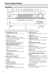
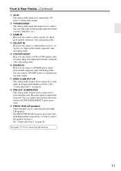
...STANDBY indicator (37) This indicator lights up when Zone 2 is used when storing or deleting radio presets. F Remote control sensor (12) This sensor receives control signals from the remote controller. G Display See "Display" on the output of Zone 2. M TUNING MODE button (53) This button is used..., 85) Used to select radio presets (see pages 53, 54). K DIMMER button (51) This button is used to set items. The [ENTER] button is being received from the remote controller. Front & Rear Panels Front Panel B C D E F G HI J K L M NO P Q R S T UV The actual front panel has various ...
...STANDBY indicator (37) This indicator lights up when Zone 2 is used when storing or deleting radio presets. F Remote control sensor (12) This sensor receives control signals from the remote controller. G Display See "Display" on the output of Zone 2. M TUNING MODE button (53) This button is used..., 85) Used to select radio presets (see pages 53, 54). K DIMMER button (51) This button is used to set items. The [ENTER] button is being received from the remote controller. Front & Rear Panels Front Panel B C D E F G HI J K L M NO P Q R S T UV The actual front panel has various ...

Owner Manual
Page 9
... Min, 1 through 79 or Max. Goes off when Manual Tuning mode is muted. G Audio input indicators Indicate the type of the AV receiver to connect a portable Audio Player. H Audyssey indicator (45, 69) Flashes during Audyssey 2EQ™ Room Correction and Speaker Setup. V SETUP...MIC jack (46) The Audyssey 2EQ™ Room Correction and Speaker Setup microphone connects here. C MUTING indicator (52) Flashes while the AV receiver is selected. D Listening mode and format indicators (59) Show the selected listening mode and audio input signal format. F Message area Displays various...
... Min, 1 through 79 or Max. Goes off when Manual Tuning mode is muted. G Audio input indicators Indicate the type of the AV receiver to connect a portable Audio Player. H Audyssey indicator (45, 69) Flashes during Audyssey 2EQ™ Room Correction and Speaker Setup. V SETUP...MIC jack (46) The Audyssey 2EQ™ Room Correction and Speaker Setup microphone connects here. C MUTING indicator (52) Flashes while the AV receiver is selected. D Listening mode and format indicators (59) Show the selected listening mode and audio input signal format. F Message area Displays various...

Owner Manual
Page 10
...'re assignable, which means you can then be connected to an V jack on page 18". See "Bi-amping the Front Speakers" on another Onkyo AV component. K V REMOTE CONTROL This V (Remote Interactive) jack can be used with optical digital audio outputs, such as CD and DVD/BD...high L/R speakers. The HDMI inputs are for connecting the front L/R, center, surround L/R, surround back L/R, and front high L/R speakers. The AV receiver's remote controller can assign each one to an input selector to control that component. They're assignable, which means you can assign each one ...
...'re assignable, which means you can then be connected to an V jack on page 18". See "Bi-amping the Front Speakers" on another Onkyo AV component. K V REMOTE CONTROL This V (Remote Interactive) jack can be used with optical digital audio outputs, such as CD and DVD/BD...high L/R speakers. The HDMI inputs are for connecting the front L/R, center, surround L/R, surround back L/R, and front high L/R speakers. The AV receiver's remote controller can assign each one to an input selector to control that component. They're assignable, which means you can assign each one ...
Owner Manual
Page 11
... IN/OUT This analog audio input and output are for connecting a CD player's analog audio output. O CBL/SAT IN Here you can connect a cable/satellite receiver, settop box, etc. The same signal is for connecting the front high L/R speakers. Input and output jacks include composite video and analog audio. R ZONE 2 LINE...
... IN/OUT This analog audio input and output are for connecting a CD player's analog audio output. O CBL/SAT IN Here you can connect a cable/satellite receiver, settop box, etc. The same signal is for connecting the front high L/R speakers. Input and output jacks include composite video and analog audio. R ZONE 2 LINE...

Owner Manual
Page 12
.../R6) in a rack behind colored glass doors. light or inverter-type fluorescent lights. Keep this in the same room, or the AV receiver is installed close to operate an Onkyo component with the polarity diagram inside the battery compartment. 3 Replace the cover and push it and the AV... receiver's remote con- Keep this in mind when installing. • If another component (page 86), or when you want to operate an Onkyo component without V connection, point the remote controller at the other component to use...
.../R6) in a rack behind colored glass doors. light or inverter-type fluorescent lights. Keep this in the same room, or the AV receiver is installed close to operate an Onkyo component with the polarity diagram inside the battery compartment. 3 Replace the cover and push it and the AV... receiver's remote con- Keep this in mind when installing. • If another component (page 86), or when you want to operate an Onkyo component without V connection, point the remote controller at the other component to use...

Owner Manual
Page 13
...(50, 90-96) Selects the remote controller modes and the input sources. You can also be controlled in Receiver mode (see the pages in the Direct tuning mode. Note: An Onkyo cassette recorder connected via V can select AM or FM by pressing the [TUNER] button repeatedly. 1 Arrow [R]/[X]... buttons Used to control your DVD/BD player, CD player, and other components. B ON/STANDBY button (37) Sets the AV receiver to select the listening modes....
...(50, 90-96) Selects the remote controller modes and the input sources. You can also be controlled in Receiver mode (see the pages in the Direct tuning mode. Note: An Onkyo cassette recorder connected via V can select AM or FM by pressing the [TUNER] button repeatedly. 1 Arrow [R]/[X]... buttons Used to control your DVD/BD player, CD player, and other components. B ON/STANDBY button (37) Sets the AV receiver to select the listening modes....

Owner Manual
Page 14
.... Their role in a movie theater or concert hall. You can enjoy Dolby Pro Logic IIx, DTS Neo:6, or Onkyo's original DSP listening modes. About Home Theater Enjoying Home Theater Thanks to the AV receiver's superb capabilities, you can enjoy DTS and Dolby Digital. Although it close to your subwoofer, while playing a movie...
.... Their role in a movie theater or concert hall. You can enjoy Dolby Pro Logic IIx, DTS Neo:6, or Onkyo's original DSP listening modes. About Home Theater Enjoying Home Theater Thanks to the AV receiver's superb capabilities, you can enjoy DTS and Dolby Digital. Although it close to your subwoofer, while playing a movie...

Owner Manual
Page 15
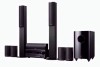
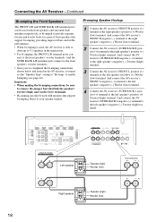
...each other, as shown. Attaching the Speaker Labels The AV receiver's positive (+) speaker terminals are all red (the negative (-) speaker terminals are all you are also color-coded and you have. Dipole speakers output the same sound in accordance with the HT-S7200 Home Theater System. • If you need to do... surround back speakers produce no sound at the same time. The surround left speaker 10.Front high right speaker 15 Connecting the AV Receiver Connecting Your Speakers Speaker Configuration For 7.1-channel surround-sound playback, you need to set the speaker settings.
...each other, as shown. Attaching the Speaker Labels The AV receiver's positive (+) speaker terminals are all red (the negative (-) speaker terminals are all you are also color-coded and you have. Dipole speakers output the same sound in accordance with the HT-S7200 Home Theater System. • If you need to do... surround back speakers produce no sound at the same time. The surround left speaker 10.Front high right speaker 15 Connecting the AV Receiver Connecting Your Speakers Speaker Configuration For 7.1-channel surround-sound playback, you need to set the speaker settings.
Owner Manual
Page 16
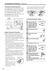
...connect them the wrong way around, the sound will sound unnatural. • Unnecessarily long, or very thin speaker cables may damage the AV receiver. 16 • Don't connect more than one speaker to the SURR L/R terminals. Powered subwoofer LINE INPUT LINE INPUT Speaker Connection Precautions Read ...making any connections. • Read the instructions supplied with an impedance of time, the built-in amp protection circuit may damage the AV receiver. • Don't connect one cable to each speaker terminal. If your subwoofer is output from the ends of the speaker cables, ...
...connect them the wrong way around, the sound will sound unnatural. • Unnecessarily long, or very thin speaker cables may damage the AV receiver. 16 • Don't connect more than one speaker to the SURR L/R terminals. Powered subwoofer LINE INPUT LINE INPUT Speaker Connection Precautions Read ...making any connections. • Read the instructions supplied with an impedance of time, the built-in amp protection circuit may damage the AV receiver. • Don't connect one cable to each speaker terminal. If your subwoofer is output from the ends of the speaker cables, ...
Owner Manual
Page 17
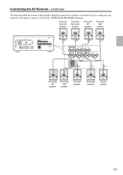
If you're using only one surround back speaker, connect it to each pair of terminals. Surround back left speaker Surround back right speaker Surround left speaker Surround right speaker Front high left speaker Front high right speaker Front left (L) SURR BACK SPEAKERS terminals. Connecting the AV Receiver-Continued The following illustration shows which speaker should be connected to the left speaker Front right speaker Center speaker 17
If you're using only one surround back speaker, connect it to each pair of terminals. Surround back left speaker Surround back right speaker Surround left speaker Surround right speaker Front high left speaker Front high right speaker Front left (L) SURR BACK SPEAKERS terminals. Connecting the AV Receiver-Continued The following illustration shows which speaker should be connected to the left speaker Front right speaker Center speaker 17
Owner Manual
Page 18
...(high) terminal. Important: • When making the bi-amping connections, be sure to the left speaker's negative (-) Woofer (low) terminal. 4 Connect the AV receiver's SURR BACK L positive (+) terminal to remove the jumper bars that link the speakers' tweeter (high) and woofer (low) terminals. • Bi-amping can be ...to the front speakers' tweeter terminals. • Once you've completed the bi-amping connections shown below and turned on the AV receiver, you must set the "Speaker Type" setting to "Bi-Amp" to the right speaker's positive (+) Tweeter (high) terminal. And connect the ...
...(high) terminal. Important: • When making the bi-amping connections, be sure to the left speaker's negative (-) Woofer (low) terminal. 4 Connect the AV receiver's SURR BACK L positive (+) terminal to remove the jumper bars that link the speakers' tweeter (high) and woofer (low) terminals. • Bi-amping can be ...to the front speakers' tweeter terminals. • Once you've completed the bi-amping connections shown below and turned on the AV receiver, you must set the "Speaker Type" setting to "Bi-Amp" to the right speaker's positive (+) Tweeter (high) terminal. And connect the ...
Owner Manual
Page 19
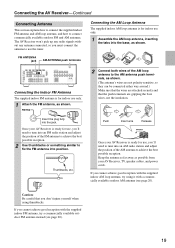
...tune into an FM radio station and adjust the position of the AM loop antenna to tune into the base, as possible from your AV Receiver is for use, you must connect the antenna to connect commercially available outdoor FM and AM antennas. Insert the plug fully into position. ...the push terminals are attached securely and that you cannot achieve good reception with a commercially available outdoor AM antenna (see page 20). 19 The AV Receiver won't pick up any radio signals without any antenna connected, so you 'll need to the AM antenna push terminals, as shown. (The antenna's...
...tune into an FM radio station and adjust the position of the AM loop antenna to tune into the base, as possible from your AV Receiver is for use, you must connect the antenna to connect commercially available outdoor FM and AM antennas. Insert the plug fully into position. ...the push terminals are attached securely and that you cannot achieve good reception with a commercially available outdoor AM antenna (see page 20). 19 The AV Receiver won't pick up any radio signals without any antenna connected, so you 'll need to the AM antenna push terminals, as shown. (The antenna's...

Owner Manual
Page 20
...prevent electrical shock hazards. ■ Using a TV/FM Antenna Splitter It's best not to the loop antenna, as shown. Connecting the AV Receiver-Continued Connecting an Outdoor FM Antenna If you cannot achieve good reception with local regulations to prevent electrical shock hazards. Connecting an Outdoor AM Antenna...usable results can cause interference problems. If circumstances demand it, use a TV/FM antenna splitter, as shown. TV/FM antenna splitter To AV Receiver To TV (or VCR) 20 Outdoor antenna must be used in addition to use the same antenna for both FM and TV reception, as...
...prevent electrical shock hazards. ■ Using a TV/FM Antenna Splitter It's best not to the loop antenna, as shown. Connecting the AV Receiver-Continued Connecting an Outdoor FM Antenna If you cannot achieve good reception with local regulations to prevent electrical shock hazards. Connecting an Outdoor AM Antenna...usable results can cause interference problems. If circumstances demand it, use a TV/FM antenna splitter, as shown. TV/FM antenna splitter To AV Receiver To TV (or VCR) 20 Outdoor antenna must be used in addition to use the same antenna for both FM and TV reception, as...

Owner Manual
Page 21
... cable Y PB/CB PR/CR Coaxial digital audio cable Y PB/CB PR/CR Analog audio cable (RCA) Stereo mini plug cable The AV receiver does not support SCART plugs. Component video separates the luminance (Y) and color difference signals (PR, PB), providing the best picture quality (some TV... other AV components. • Don't connect the power cord until you've completed and double-checked all AV components. Connecting the AV Receiver-Continued About AV Connections • Before making any AV connections, read the manuals supplied with your other video equipment. Optical Digital Jacks The AV...
... cable Y PB/CB PR/CR Coaxial digital audio cable Y PB/CB PR/CR Analog audio cable (RCA) Stereo mini plug cable The AV receiver does not support SCART plugs. Component video separates the luminance (Y) and color difference signals (PR, PB), providing the best picture quality (some TV... other AV components. • Don't connect the power cord until you've completed and double-checked all AV components. Connecting the AV Receiver-Continued About AV Connections • Before making any AV connections, read the manuals supplied with your other video equipment. Optical Digital Jacks The AV...

Owner Manual
Page 22
...Controlling a DVD/BD Player, or DVD/BD Recorder" (page 91) for high-performance PCs and digital displays. 22 The AV receiver's HDMI interface is based on Onkyo components. tion. Other devices connected to four. With HDMI, a single cable can carry control signals, digital video, and up... to the AV receiver via HDMI. Do not connect the AV receiver to the other than the following standard: x.v.Color, Deep ...
...Controlling a DVD/BD Player, or DVD/BD Recorder" (page 91) for high-performance PCs and digital displays. 22 The AV receiver's HDMI interface is based on Onkyo components. tion. Other devices connected to four. With HDMI, a single cable can carry control signals, digital video, and up... to the AV receiver via HDMI. Do not connect the AV receiver to the other than the following standard: x.v.Color, Deep ...


