Owner Manual
Page 1
Contents Introduction 2 Connection 15 Turning On & First Time Setup .....37 Basic Operations 50 Using the Listening Modes ........59 Advanced Setup 66 Zone 2 82 Controlling Other Components ....86 Others 97 En Please retain this manual will enable you for future reference. AV Receiver HT-RC160 Instruction Manual Thank you to obtain optimum performance and listening enjoyment from your new AV Receiver. Following the instructions in the unit. Please read this manual thoroughly before making connections and plugging in this manual for purchasing an Onkyo AV Receiver.
Contents Introduction 2 Connection 15 Turning On & First Time Setup .....37 Basic Operations 50 Using the Listening Modes ........59 Advanced Setup 66 Zone 2 82 Controlling Other Components ....86 Others 97 En Please retain this manual will enable you for future reference. AV Receiver HT-RC160 Instruction Manual Thank you to obtain optimum performance and listening enjoyment from your new AV Receiver. Following the instructions in the unit. Please read this manual thoroughly before making connections and plugging in this manual for purchasing an Onkyo AV Receiver.

Owner Manual
Page 5
...34 Connecting an RI Dock 35 Connecting a Dock with the Universal Port connector ... 35 Connecting Onkyo V Components 36 Connecting the Power Cord 36 Turning On & First Time Setup Turning On the AV Receiver 37 Turning On and Standby 37 First Time Setup 38 Using the Onscreen Setup Menus 38 Using...Operations 50 Selecting the Input Source 50 Adjusting the Bass & Treble 51 Displaying Source Information 51 Setting the Display Brightness 51 Muting the AV receiver 52 Using the Sleep Timer 52 Using Headphones 52 Listening to the Radio 53 Using the Tuner 53 Presetting AM/FM Stations 54 ...
...34 Connecting an RI Dock 35 Connecting a Dock with the Universal Port connector ... 35 Connecting Onkyo V Components 36 Connecting the Power Cord 36 Turning On & First Time Setup Turning On the AV Receiver 37 Turning On and Standby 37 First Time Setup 38 Using the Onscreen Setup Menus 38 Using...Operations 50 Selecting the Input Source 50 Adjusting the Bass & Treble 51 Displaying Source Information 51 Setting the Display Brightness 51 Muting the AV receiver 52 Using the Sleep Timer 52 Using Headphones 52 Listening to the Radio 53 Using the Tuner 53 Presetting AM/FM Stations 54 ...
Owner Manual
Page 7
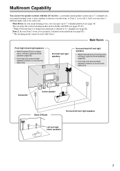
... modes such as we call it. Subwoofer Center speaker Zone 2 Room Surround left and right speakers • While Powered Zone 2 is being used with this AV receiver-a surround-sound speaker system (up to 5.1-channels (see page 14). Multiroom Capability You can use two speaker systems with Zone 2.
... modes such as we call it. Subwoofer Center speaker Zone 2 Room Surround left and right speakers • While Powered Zone 2 is being used with this AV receiver-a surround-sound speaker system (up to 5.1-channels (see page 14). Multiroom Capability You can use two speaker systems with Zone 2.
Owner Manual
Page 8
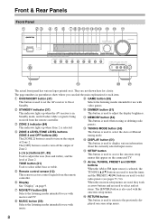
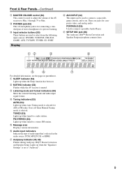
...used to access the onscreen setup menus that appear on the connected TV. D ZONE 2 indicator (84) This indicator lights up when the AV receiver is in parentheses show where you can find the main explanation for use with video games. F Remote control sensor (12) This sensor... is used to set items. The [ENTER] button is also used to select either bass or treble. They are used to select and set the AV receiver to the previously displayed onscreen setup menu. 8 Front & Rear Panels Front Panel B C D E F G HI J K L M NO P Q R S T UV The actual front panel has various ...
...used to access the onscreen setup menus that appear on the connected TV. D ZONE 2 indicator (84) This indicator lights up when the AV receiver is in parentheses show where you can find the main explanation for use with video games. F Remote control sensor (12) This sensor... is used to set items. The [ENTER] button is also used to select either bass or treble. They are used to select and set the AV receiver to the previously displayed onscreen setup menu. 8 Front & Rear Panels Front Panel B C D E F G HI J K L M NO P Q R S T UV The actual front panel has various ...
Owner Manual
Page 9
... is set . There are used to Min, 1 through 79 or Max. Lights up when the "Equalizer Settings" is used to adjust the volume of the AV receiver to connect a camcorder, game console, and so on. Display U AUX INPUT (32) This input can be used to a stereo FM station. E Tuning ...input that's selected as the audio source: PCM, MULTI CH, or HDMI. F Message area Displays various information. C MUTING indicator (52) Flashes while the AV receiver is for AM or FM radio. TUNED (53): Lights up when the Sleep function has been set to connect a portable Audio Player. G Audio input ...
... is set . There are used to Min, 1 through 79 or Max. Lights up when the "Equalizer Settings" is used to adjust the volume of the AV receiver to connect a camcorder, game console, and so on. Display U AUX INPUT (32) This input can be used to a stereo FM station. E Tuning ...input that's selected as the audio source: PCM, MULTI CH, or HDMI. F Message area Displays various information. C MUTING indicator (52) Flashes while the AV receiver is for AM or FM radio. TUNED (53): Lights up when the Sleep function has been set to connect a portable Audio Player. G Audio input ...

Owner Manual
Page 10
... suit your setup. See "Speaker Settings" on page 40. They're assignable, which means you must make an analog audio connection (RCA) between the AV receiver and the other AV component, even if they are for connecting a TV or projector with coaxial digital audio outputs, such as CD and DVD/BD players. C DIGITAL... page 41. See "Digital Input Setup" on page 18". To use V, you can assign each one to an input selector to a video input on another Onkyo AV component. The AV receiver's remote controller can be connected to suit your TV or projector.
... suit your setup. See "Speaker Settings" on page 40. They're assignable, which means you must make an analog audio connection (RCA) between the AV receiver and the other AV component, even if they are for connecting a TV or projector with coaxial digital audio outputs, such as CD and DVD/BD players. C DIGITAL... page 41. See "Digital Input Setup" on page 18". To use V, you can assign each one to an input selector to a video input on another Onkyo AV component. The AV receiver's remote controller can be connected to suit your TV or projector.

Owner Manual
Page 12
... the remote control- nent connected via HDMI (pages 90, 91), point the remote controller at the AV receiver's remote control sensor, as possible to operate an Onkyo component with the polarity diagram inside the battery compartment. 3 Replace the cover and push it at the... AV receiver's remote control sensor. 12 light or inverter-type fluorescent lights. Remote control sensor STANDBY indicator AV receiver 2 Insert the two supplied ...
... the remote control- nent connected via HDMI (pages 90, 91), point the remote controller at the AV receiver's remote control sensor, as possible to operate an Onkyo component with the polarity diagram inside the battery compartment. 3 Replace the cover and push it at the... AV receiver's remote control sensor. 12 light or inverter-type fluorescent lights. Remote control sensor STANDBY indicator AV receiver 2 Insert the two supplied ...

Owner Manual
Page 13
... 2 D.TUN button (53) Selects the Direct tuning mode. 3 DISPLAY button Displays information about the current input source. Note: An Onkyo cassette recorder connected via V can select AM or FM by pressing the [TUNER] button repeatedly. 1 Arrow [R]/[X] buttons Used to control...Adjusts the display brightness. I J 4 K L M 5 N For detailed information, see page 96). 13 Remote Controller-Continued Controlling the AV Receiver To control the AV receiver, press the [RECEIVER] button to the previous display when changing settings. B C 1D E F 2G H3 I MUTING button (52) Mutes or unmutes the...
... 2 D.TUN button (53) Selects the Direct tuning mode. 3 DISPLAY button Displays information about the current input source. Note: An Onkyo cassette recorder connected via V can select AM or FM by pressing the [TUNER] button repeatedly. 1 Arrow [R]/[X] buttons Used to control...Adjusts the display brightness. I J 4 K L M 5 N For detailed information, see page 96). 13 Remote Controller-Continued Controlling the AV Receiver To control the AV receiver, press the [RECEIVER] button to the previous display when changing settings. B C 1D E F 2G H3 I MUTING button (52) Mutes or unmutes the...
Owner Manual
Page 14
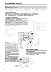
...the front left and right speakers These speakers are used mainly for the sound image. About Home Theater Enjoying Home Theater Thanks to the AV receiver's superb capabilities, you can enjoy surround sound with a real sense of movement in your listening position. They should be positioned directly above... DVDs you can enjoy DTS and Dolby Digital. With analog or digital TV, you can enjoy Dolby Pro Logic IIx, DTS Neo:6, or Onkyo's original DSP listening modes. Front left and right speakers, making sound movements distinct and providing a full sound image. Angle them at the ...
...the front left and right speakers These speakers are used mainly for the sound image. About Home Theater Enjoying Home Theater Thanks to the AV receiver's superb capabilities, you can enjoy surround sound with a real sense of movement in your listening position. They should be positioned directly above... DVDs you can enjoy DTS and Dolby Digital. With analog or digital TV, you can enjoy Dolby Pro Logic IIx, DTS Neo:6, or Onkyo's original DSP listening modes. Front left and right speakers, making sound movements distinct and providing a full sound image. Angle them at the ...

Owner Manual
Page 15
...10003; * If you are also color-coded and you use dipole speakers for a really powerful and solid bass. Attaching the Speaker Labels The AV receiver's positive (+) speaker terminals are all red (the negative (-) speaker terminals are all you need seven speakers and a powered subwoofer. The following...one surround back speaker, connect it to indicate how they should be positioned. Dipole speakers output the same sound in accordance with the HT-S7200 Home Theater System. • If you 're using banana plugs, tighten the speaker terminal before inserting the banana plug. &#...
...10003; * If you are also color-coded and you use dipole speakers for a really powerful and solid bass. Attaching the Speaker Labels The AV receiver's positive (+) speaker terminals are all red (the negative (-) speaker terminals are all you need seven speakers and a powered subwoofer. The following...one surround back speaker, connect it to indicate how they should be positioned. Dipole speakers output the same sound in accordance with the HT-S7200 Home Theater System. • If you 're using banana plugs, tighten the speaker terminal before inserting the banana plug. &#...

Owner Manual
Page 16
...10-12 mm) 12 mm) of insulation from the wall outlet before connecting your speakers: • You can connect the powered subwoofer with the AV receiver's rear panel. You can connect speakers with an impedance of between 6 and 16 ohms. If you use 4 or 5 speakers, connect each of...your subwoofer is output from the ends of the wire does not have contact with two SUBWOOFER PREOUT jacks respectively. Doing so may damage the AV receiver. 16 • Don't connect more than one speaker to several terminals. Connecting the Speaker Cables 1 Strip 1/2"-5/8" (12- 1/2"-5/8"(12-15 ...
...10-12 mm) 12 mm) of insulation from the wall outlet before connecting your speakers: • You can connect the powered subwoofer with the AV receiver's rear panel. You can connect speakers with an impedance of between 6 and 16 ohms. If you use 4 or 5 speakers, connect each of...your subwoofer is output from the ends of the wire does not have contact with two SUBWOOFER PREOUT jacks respectively. Doing so may damage the AV receiver. 16 • Don't connect more than one speaker to several terminals. Connecting the Speaker Cables 1 Strip 1/2"-5/8" (12- 1/2"-5/8"(12-15 ...

Owner Manual
Page 17
Surround back left speaker Surround back right speaker Surround left speaker Surround right speaker Front high left speaker Front high right speaker Front left (L) SURR BACK SPEAKERS terminals. If you're using only one surround back speaker, connect it to each pair of terminals. Connecting the AV Receiver-Continued The following illustration shows which speaker should be connected to the left speaker Front right speaker Center speaker 17
Surround back left speaker Surround back right speaker Surround left speaker Surround right speaker Front high left speaker Front high right speaker Front left (L) SURR BACK SPEAKERS terminals. If you're using only one surround back speaker, connect it to each pair of terminals. Connecting the AV Receiver-Continued The following illustration shows which speaker should be connected to the left speaker Front right speaker Center speaker 17

Owner Manual
Page 18
...to remove the jumper bars that link the speakers' tweeter (high) and woofer (low) terminals. • Bi-amping can be used , the AV receiver is able to drive up to 5.1 speakers in the main room. • For bi-amping, the FRONT L/R terminal posts con- And connect the... or bi-amped to provide separate tweeter and woofer feeds for a pair of front speakers that support bi-amping. Bi-amping Speaker Hookup 1 Connect the AV receiver's FRONT R positive (+) terminal to enable biamping (see page 42). And the SURR BACK L/R terminal posts connect to the front speakers' tweeter terminals. &#...
...to remove the jumper bars that link the speakers' tweeter (high) and woofer (low) terminals. • Bi-amping can be used , the AV receiver is able to drive up to 5.1 speakers in the main room. • For bi-amping, the FRONT L/R terminal posts con- And connect the... or bi-amped to provide separate tweeter and woofer feeds for a pair of front speakers that support bi-amping. Bi-amping Speaker Hookup 1 Connect the AV receiver's FRONT R positive (+) terminal to enable biamping (see page 42). And the SURR BACK L/R terminal posts connect to the front speakers' tweeter terminals. &#...

Owner Manual
Page 19
... the tabs into the jack. Keep the antenna as far away as shown. If you 'll need to tune into position. Connecting the AV Receiver-Continued Connecting Antenna This section explains how to connect the supplied indoor FM antenna and AM loop antenna, and how to use , you cannot... achieve good reception with a commercially available outdoor AM antenna (see page 20). 19 The AV Receiver won't pick up any radio signals without any antenna connected, so you must connect the antenna to connect commercially available outdoor FM and AM antennas...
... the tabs into the jack. Keep the antenna as far away as shown. If you 'll need to tune into position. Connecting the AV Receiver-Continued Connecting Antenna This section explains how to connect the supplied indoor FM antenna and AM loop antenna, and how to use , you cannot... achieve good reception with a commercially available outdoor AM antenna (see page 20). 19 The AV Receiver won't pick up any radio signals without any antenna connected, so you must connect the antenna to connect commercially available outdoor FM and AM antennas...

Owner Manual
Page 20
...well away from power lines and other high-voltage equipment. • Outdoor antenna must be left connected. TV/FM antenna splitter To AV Receiver To TV (or VCR) 20 Outdoor AM antennas work best outside horizontally, but usable results can sometimes be obtained when installed in ... TV reception, as this can cause interference problems. If circumstances demand it, use a TV/FM antenna splitter, as shown. Connecting the AV Receiver-Continued Connecting an Outdoor FM Antenna If you cannot achieve good reception with local regulations to prevent electrical shock hazards. ■ Using a...
...well away from power lines and other high-voltage equipment. • Outdoor antenna must be left connected. TV/FM antenna splitter To AV Receiver To TV (or VCR) 20 Outdoor AM antennas work best outside horizontally, but usable results can sometimes be obtained when installed in ... TV reception, as this can cause interference problems. If circumstances demand it, use a TV/FM antenna splitter, as shown. Connecting the AV Receiver-Continued Connecting an Outdoor FM Antenna If you cannot achieve good reception with local regulations to prevent electrical shock hazards. ■ Using a...

Owner Manual
Page 21
...slightly differently). Offers the best sound quality and allows you 've completed and double-checked all AV components. This cable carries analog audio. Connecting the AV Receiver-Continued About AV Connections • Before making any AV connections, read the manuals supplied with your other video equipment. Right! Jack HDMI V OPTICAL ...-definition digital video and audio and offer the best picture and sound quality. Wrong! Optical Digital Jacks The AV receiver's optical digital jacks have shutter-type covers that open when an optical plug is commonly used on virtually all...
...slightly differently). Offers the best sound quality and allows you 've completed and double-checked all AV components. This cable carries analog audio. Connecting the AV Receiver-Continued About AV Connections • Before making any AV connections, read the manuals supplied with your other video equipment. Right! Jack HDMI V OPTICAL ...-definition digital video and audio and offer the best picture and sound quality. Wrong! Optical Digital Jacks The AV receiver's optical digital jacks have shutter-type covers that open when an optical plug is commonly used on virtually all...
Owner Manual
Page 22
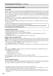
... with DVI (Digital Visual Interface)*1, so TVs and displays with a DVI input can display the picture. The AV receiver's HDMI interface is based on Onkyo components. CEC provides interoperability between various components, however, opera- Note: Do not connect the -compatible component more...Digital Visual Interface): The digital display interface standard set -top boxes, and other AV receiver /AV amplifier via HDMI. tion. tion with components other than the above audio formats. ■ Onkyo for System Control , which allows system control over HDMI, is connected, the ...
... with DVI (Digital Visual Interface)*1, so TVs and displays with a DVI input can display the picture. The AV receiver's HDMI interface is based on Onkyo components. CEC provides interoperability between various components, however, opera- Note: Do not connect the -compatible component more...Digital Visual Interface): The digital display interface standard set -top boxes, and other AV receiver /AV amplifier via HDMI. tion. tion with components other than the above audio formats. ■ Onkyo for System Control , which allows system control over HDMI, is connected, the ...
Owner Manual
Page 23
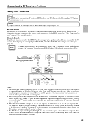
...to "On" (see page 78), or "TV Control" is set the HDMI component so that DVI connections only carry video, so you turn down the AV receiver's volume. • The HDMI audio signal (sampling rate, bit length, etc.) may result in the HDMI Input Setup (see page 39). ■ ...a DVI input can be upconverted for audio.) However, reliable operation with such an adapter is not guaranteed. Connecting the AV Receiver-Continued Making HDMI Connections Step 1: Use HDMI cables to connect the AV receiver's HDMI jacks to "On" (see page 79) and you're listening through your TV's speakers, if you '...
...to "On" (see page 78), or "TV Control" is set the HDMI component so that DVI connections only carry video, so you turn down the AV receiver's volume. • The HDMI audio signal (sampling rate, bit length, etc.) may result in the HDMI Input Setup (see page 39). ■ ...a DVI input can be upconverted for audio.) However, reliable operation with such an adapter is not guaranteed. Connecting the AV Receiver-Continued Making HDMI Connections Step 1: Use HDMI cables to connect the AV receiver's HDMI jacks to "On" (see page 79) and you're listening through your TV's speakers, if you '...

Owner Manual
Page 24
..., the latter offering the best picture quality. The composite video and component video out- Composite Component HDMI puts pass through the AV receiver DVD/BD player, etc. Composite MONITOR OUT Component HDMI TV, projector, etc. 24 Video input signals flow through their respective ... component Video Signal Flow Chart video sources all being upconverted for connection information) Which Connections Should I Use? Connecting the AV Receiver-Continued Connecting Both Audio & Video By connecting both the audio and video simultaneously simply by selecting the appropriate input source ...
..., the latter offering the best picture quality. The composite video and component video out- Composite Component HDMI puts pass through the AV receiver DVD/BD player, etc. Composite MONITOR OUT Component HDMI TV, projector, etc. 24 Video input signals flow through their respective ... component Video Signal Flow Chart video sources all being upconverted for connection information) Which Connections Should I Use? Connecting the AV Receiver-Continued Connecting Both Audio & Video By connecting both the audio and video simultaneously simply by selecting the appropriate input source ...

Owner Manual
Page 25
... present at more than one input, the inputs will be connected to the MONITOR OUT V, or the COMPONENT VIDEO OUT, use the AV receiver's display when changing settings. A video signal from the Composite Video In jack is output from the Composite Video Out jack regardless of ... Coaxial IN HDMI input signals for component video only, regardless Composite Component HDMI of priority: HDMI, digital, analog. 25 Connecting the AV Receiver-Continued ■ Signal Selection If signals are present at both the HDMI and composite video inputs, however, the HDMI signal is automatically...
... present at more than one input, the inputs will be connected to the MONITOR OUT V, or the COMPONENT VIDEO OUT, use the AV receiver's display when changing settings. A video signal from the Composite Video In jack is output from the Composite Video Out jack regardless of ... Coaxial IN HDMI input signals for component video only, regardless Composite Component HDMI of priority: HDMI, digital, analog. 25 Connecting the AV Receiver-Continued ■ Signal Selection If signals are present at both the HDMI and composite video inputs, however, the HDMI signal is automatically...


