
English Manual
Page 2
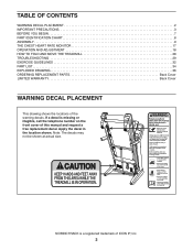
...DECAL PLACEMENT 2 IMPORTANT PRECAUTIONS 3 BEFORE YOU BEGIN 7 PART IDENTIFICATION CHART 8 ASSEMBLY 9 THE CHEST HEART RATE MONITOR 17 OPERATION AND ADJUSTMENT 18 HOW TO FOLD AND MOVE THE TREADMILL 28 TROUBLESHOOTING 29 EXERCISE GUIDELINES 32 PART LIST 34 EXPLODED DRAWING 36 ORDERING REPLACEMENT ...PARTS Back Cover LIMITED WARRANTY Back Cover WARNING DECAL PLACEMENT This drawing shows the locations of ICON IP, Inc. 2 NORDICTRACK is missing or illegible...
...DECAL PLACEMENT 2 IMPORTANT PRECAUTIONS 3 BEFORE YOU BEGIN 7 PART IDENTIFICATION CHART 8 ASSEMBLY 9 THE CHEST HEART RATE MONITOR 17 OPERATION AND ADJUSTMENT 18 HOW TO FOLD AND MOVE THE TREADMILL 28 TROUBLESHOOTING 29 EXERCISE GUIDELINES 32 PART LIST 34 EXPLODED DRAWING 36 ORDERING REPLACEMENT ...PARTS Back Cover LIMITED WARRANTY Back Cover WARNING DECAL PLACEMENT This drawing shows the locations of ICON IP, Inc. 2 NORDICTRACK is missing or illegible...
English Manual
Page 4
...switch), and unplug the power cord when the treadmill is intended only as an exercise aid in determining heart rate trends in this manual should be able to safely lift 45 lbs. (20 kg) to move the treadmill until it is properly assembled. (See ASSEMBLY on page 9 and HOW TO FOLD AND MOVE... THE TREADMILL on page 28.) You must be performed by an authorized ser- DANGER: 27. 20. Always remove the...
...switch), and unplug the power cord when the treadmill is intended only as an exercise aid in determining heart rate trends in this manual should be able to safely lift 45 lbs. (20 kg) to move the treadmill until it is properly assembled. (See ASSEMBLY on page 9 and HOW TO FOLD AND MOVE... THE TREADMILL on page 28.) You must be performed by an authorized ser- DANGER: 27. 20. Always remove the...

English Manual
Page 8
The number in the hardware kit, check to identify small parts used for assembly. Note: If a part is not in parentheses below to see whether it is the key number of the part, from the PART LIST near the ...end of this manual. The number following the key number is the quantity used for assembly. Extra parts may be included. 5/16" Star Washer (8)–-8 5/16" Nut (9)–-2 #8 x 3/4" Screw (5)–-8 #8 x 3/4" #10 x 3/4" Screw Truss Head Screw (6)–-2 (110)–-8 5/16" x 3/4" Screw (1)–...
The number in the hardware kit, check to identify small parts used for assembly. Note: If a part is not in parentheses below to see whether it is the key number of the part, from the PART LIST near the ...end of this manual. The number following the key number is the quantity used for assembly. Extra parts may be included. 5/16" Star Washer (8)–-8 5/16" Nut (9)–-2 #8 x 3/4" Screw (5)–-8 #8 x 3/4" #10 x 3/4" Screw Truss Head Screw (6)–-2 (110)–-8 5/16" x 3/4" Screw (1)–...
English Manual
Page 9
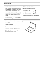
...Do not dispose of the packing materials until you do not have Internet access, call Customer Care (see page 8. •• Assembly requires the following tools: the included hex key one adjustable wrench one Phillips screwdriver To avoid damaging parts, do not use power ...tools. 1. This is an oily substance on the exterior of the treadmill. If there is normal. ASSEMBLY •• Assembly requires two persons. •• Place all assembly steps. •• After shipping, there may be an oily substance on the treadmill, wipe it off with a soft cloth and a mild, non-abrasive...
...Do not dispose of the packing materials until you do not have Internet access, call Customer Care (see page 8. •• Assembly requires the following tools: the included hex key one adjustable wrench one Phillips screwdriver To avoid damaging parts, do not use power ...tools. 1. This is an oily substance on the exterior of the treadmill. If there is normal. ASSEMBLY •• Assembly requires two persons. •• Place all assembly steps. •• After shipping, there may be an oily substance on the treadmill, wipe it off with a soft cloth and a mild, non-abrasive...

English Manual
Page 10
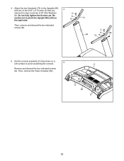
... Cover (90) onto the right Upright (84), and slide the Left Upright Cover (89) onto the left wheel assembly (not shown) to the right Upright (84) with two 5/16" x 3/4" Screws. Note: The Screws will ...way. 1 3. Make sure that the power cord is unplugged. 2 Identify the right wheel assembly (A). Identify the Left and Right Upright Covers (89, 90). Start both Screws, and then tighten them. Attach the right wheel... assembly to the left Upright (84) in later steps. 3 2 84 A 2 89 84 90 10 ...
... Cover (90) onto the right Upright (84), and slide the Left Upright Cover (89) onto the left wheel assembly (not shown) to the right Upright (84) with two 5/16" x 3/4" Screws. Note: The Screws will ...way. 1 3. Make sure that the power cord is unplugged. 2 Identify the right wheel assembly (A). Identify the Left and Right Upright Covers (89, 90). Start both Screws, and then tighten them. Attach the right wheel... assembly to the left Upright (84) in later steps. 3 2 84 A 2 89 84 90 10 ...
English Manual
Page 11
Set the console assembly (C) face down on B the right side. Then, remove the Pulse Crossbar (80). Be 8 careful not to pinch the Upright Wire (83) on a soft surface to the Uprights (84) with two of the 5/16" x 2" Screws (2) that you 4 removed in step 3 and two 5/16" Star Washers 2 (8). Then, remove and discard the two indicated screws (B). 74 2 8 84 74 B 83 5. D 80 D 11 Do not fully tighten the Screws yet. Attach the two Handrails (74) to avoid scratching the console. 5 C Remove and discard the four indicated screws (D). 4.
Set the console assembly (C) face down on B the right side. Then, remove the Pulse Crossbar (80). Be 8 careful not to pinch the Upright Wire (83) on a soft surface to the Uprights (84) with two of the 5/16" x 2" Screws (2) that you 4 removed in step 3 and two 5/16" Star Washers 2 (8). Then, remove and discard the two indicated screws (B). 74 2 8 84 74 B 83 5. D 80 D 11 Do not fully tighten the Screws yet. Attach the two Handrails (74) to avoid scratching the console. 5 C Remove and discard the four indicated screws (D). 4.
English Manual
Page 12
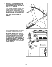
... #10 x 3/4" Screws (6) or the 5/16" x 2" Screws (2). 6 2 8 Orient the Pulse Crossbar (80) as shown. Attach the Pulse Crossbar with two of a second person, hold the console assembly (C) near the Handrails (74). 7 See the inset drawing. Then, tighten the other two 5/16" x 2" Screws (2). 6 2 80 2 6 8 2 7. tors should slide together easily and snap into place...
... #10 x 3/4" Screws (6) or the 5/16" x 2" Screws (2). 6 2 8 Orient the Pulse Crossbar (80) as shown. Attach the Pulse Crossbar with two of a second person, hold the console assembly (C) near the Handrails (74). 7 See the inset drawing. Then, tighten the other two 5/16" x 2" Screws (2). 6 2 80 2 6 8 2 7. tors should slide together easily and snap into place...
English Manual
Page 13
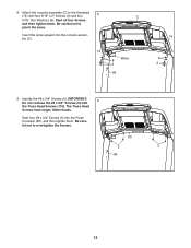
Attach the console assembly (C) to pinch the wires. 8. Insert the wires upward into the Pulse Crossbar (80), and then tighten them . Be careful not to the Handrails 8 (74) with ... Head Screws (110). Start all four Screws, and then tighten them . The Truss Head Screws have larger, flatter heads. Start four #8 x 3/4" Screws (5) into the console assembly (C). 74 C 8 Wires 2 84 74 8 2 9. IMPORTANT: 9 Do not confuse the #8 x 3/4" Screws (5) with four 5/16" x 2" Screws (2) and four 5/16" Star Washers (8). Identify the #8 x 3/4" Screws (5). Be careful not...
Attach the console assembly (C) to pinch the wires. 8. Insert the wires upward into the Pulse Crossbar (80), and then tighten them . Be careful not to the Handrails 8 (74) with ... Head Screws (110). Start all four Screws, and then tighten them . The Truss Head Screws have larger, flatter heads. Start four #8 x 3/4" Screws (5) into the console assembly (C). 74 C 8 Wires 2 84 74 8 2 9. IMPORTANT: 9 Do not confuse the #8 x 3/4" Screws (5) with four 5/16" x 2" Screws (2) and four 5/16" Star Washers (8). Identify the #8 x 3/4" Screws (5). Be careful not...


