
Software Guide
Page 3
Contents Chapter 1 Getting Started Getting Started with the NETGEAR Switch 10 Switch Management Interface 11 Connect the Switch to the Network 12 Discover a Switch in a Network with a DHCP Server 13 Discover a Switch in a Network ... IP Configuration 44 IPv6 Network Configuration 46 IPv6 Network Neighbor 47 Time 48 Denial of Service 53 DNS 55 Green Ethernet 58 License 63 Switch Stack Configuration 64 Stacking Overview 64 Basic Stack Configuration 66 Advanced Stack Configuration 69 Advanced Stack Status 69 Advanced Stack-Port Configuration 71 Advanced Stack-Port Diagnostics 72 3
Contents Chapter 1 Getting Started Getting Started with the NETGEAR Switch 10 Switch Management Interface 11 Connect the Switch to the Network 12 Discover a Switch in a Network with a DHCP Server 13 Discover a Switch in a Network ... IP Configuration 44 IPv6 Network Configuration 46 IPv6 Network Neighbor 47 Time 48 Denial of Service 53 DNS 55 Green Ethernet 58 License 63 Switch Stack Configuration 64 Stacking Overview 64 Basic Stack Configuration 66 Advanced Stack Configuration 69 Advanced Stack Status 69 Advanced Stack-Port Configuration 71 Advanced Stack-Port Diagnostics 72 3

Software Guide
Page 4
S3300 Smart Switch Multiple Stack Links 74 PoE 76 Advanced PoE Configuration 77 Advanced PoE Port Configuration 77 SNMP 80 Configure the SNMPv1/v2 Community 80 LLDP 84 LLDP Configuration ...
S3300 Smart Switch Multiple Stack Links 74 PoE 76 Advanced PoE Configuration 77 Advanced PoE Port Configuration 77 SNMP 80 Configure the SNMPv1/v2 Community 80 LLDP 84 LLDP Configuration ...
Software Guide
Page 22
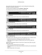
... disabled. • Black indicates that no link is present. S3300-52X The following image shows the Device View of the S3300-28X-PoE+. Getting Started 22 S3300-28X-PoE+ The following image shows the Device View of the S3300-28X. Figure 12. Figure 11. Figure 10. Depending upon the ...status, table information, and feature components. S3300-28X The following image shows the Device View of the port, the port color in Ethernet mode, then their color is gray. • When these ports are configured in Device View is either Stacking mode or in Ethernet mode. •...
... disabled. • Black indicates that no link is present. S3300-52X The following image shows the Device View of the S3300-28X-PoE+. Getting Started 22 S3300-28X-PoE+ The following image shows the Device View of the S3300-28X. Figure 12. Figure 11. Figure 10. Depending upon the ...status, table information, and feature components. S3300-28X The following image shows the Device View of the port, the port color in Ethernet mode, then their color is gray. • When these ports are configured in Device View is either Stacking mode or in Ethernet mode. •...
Software Guide
Page 24
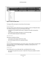
... LEDs are given by the following indications are located on the bottom right glows when either the unit is a Stack Manager or Standalone (meaning that power is for the S3300-28X-PoE+ and S3300-52X-PoE+ devices. • Off indicates the system has more than 7 watts (W) of power and diagnostic ...status. Getting Started 24 PoE Max LED The PoE Max LED is disconnected. Stack ID LED The seven Segment LED displays the...
... LEDs are given by the following indications are located on the bottom right glows when either the unit is a Stack Manager or Standalone (meaning that power is for the S3300-28X-PoE+ and S3300-52X-PoE+ devices. • Off indicates the system has more than 7 watts (W) of power and diagnostic ...status. Getting Started 24 PoE Max LED The PoE Max LED is disconnected. Stack ID LED The seven Segment LED displays the...
Software Guide
Page 27
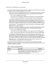
...ports supporting both 10G and 1000M speeds The dedicated 10GBaseT and SFP+ ports can be stacked together to the S3300-28X except it supports PoE+ on the 24 1G ports. • S3300-52X. Interface naming conventions Interface Physical Description Example The physical ports include gigabit ports and ...business class switch.This 28-port Gigabit Ethernet Layer 2 switch provides ports as stacking links. This switch supports management via IPv4 and IPv6, supports 32 Static Routes, and provides Green Ethernet (EEE) capability. • S3300-28X-PoE+. X for the unit ID, g is for a 1G port, ...
...ports supporting both 10G and 1000M speeds The dedicated 10GBaseT and SFP+ ports can be stacked together to the S3300-28X except it supports PoE+ on the 24 1G ports. • S3300-52X. Interface naming conventions Interface Physical Description Example The physical ports include gigabit ports and ...business class switch.This 28-port Gigabit Ethernet Layer 2 switch provides ports as stacking links. This switch supports management via IPv4 and IPv6, supports 32 Static Routes, and provides Green Ethernet (EEE) capability. • S3300-28X-PoE+. X for the unit ID, g is for a 1G port, ...

Software Guide
Page 35
2. Configure System Information 2 Use the features you access from the System navigation tab to define the switch's relationship to the configuration menus described in the following sections: • Management on page 36 • Device View on page 62 • License on page 63 • Switch Stack Configuration on page 64 • PoE on page 76 • SNMP on page 80 • LLDP on page 84 • Services on page 95 • Timer Schedule on page 109 35 The System navigation tab provides access to its environment.
2. Configure System Information 2 Use the features you access from the System navigation tab to define the switch's relationship to the configuration menus described in the following sections: • Management on page 36 • Device View on page 62 • License on page 63 • Switch Stack Configuration on page 64 • PoE on page 76 • SNMP on page 80 • LLDP on page 84 • Services on page 95 • Timer Schedule on page 109 35 The System navigation tab provides access to its environment.

Software Guide
Page 37
...blank. • System Location. Enter the contact person for the given unit. The following table describes the status information displayed in the stack. The current date and time. The temperature is instant and can use to 255 alphanumeric characters. Define the following fields: •... 20. Temperature Sensors Status Fields Field Unit Sensor Description The unit number in the Temperature Sensors section of the System Information screen. S3300 Smart Switch 2. The temperature sensor for this switch. Table 4. The base object ID for the switch's enterprise MIB. You can...
...blank. • System Location. Enter the contact person for the given unit. The following table describes the status information displayed in the stack. The current date and time. The temperature is instant and can use to 255 alphanumeric characters. Define the following fields: •... 20. Temperature Sensors Status Fields Field Unit Sensor Description The unit number in the Temperature Sensors section of the System Information screen. S3300 Smart Switch 2. The temperature sensor for this switch. Table 4. The base object ID for the switch's enterprise MIB. You can...

Software Guide
Page 38
...fixed or removable. Figure 22. The unit temperature state. Fan Status The following table describes the status information displayed in the stack. System Information - System Information - Specifies whether the fan module is running or stopped. The maximum temperature depends on the actual...State Max Temp Description The description of the System Information screen. Table 6. Power Supplies This screen shows the power supplies status. S3300 Smart Switch Table 5. The description of the fans. Fans The screen shows the status of the temperature sensor. These fans ...
...fixed or removable. Figure 22. The unit temperature state. Fan Status The following table describes the status information displayed in the stack. System Information - System Information - Specifies whether the fan module is running or stopped. The maximum temperature depends on the actual...State Max Temp Description The description of the System Information screen. Table 6. Power Supplies This screen shows the power supplies status. S3300 Smart Switch Table 5. The description of the fans. Fans The screen shows the status of the temperature sensor. These fans ...

Software Guide
Page 39
... load, and stability parameters of the System Information screen. Table 7. Specifies whether the power modules is fixed or removable. S3300 Smart Switch The following table describes the information displayed in the Versions section of the switch. System Information - Table 8. ...Power Supplies Status Fields Field Unit Power Supply Description Type State Description The unit number in the stack. Indicates whether the power supply is operational or stopped. Figure 23. Configure System Information 39 Versions This screen displays the...
... load, and stability parameters of the System Information screen. Table 7. Specifies whether the power modules is fixed or removable. S3300 Smart Switch The following table describes the information displayed in the Versions section of the switch. System Information - Table 8. ...Power Supplies Status Fields Field Unit Power Supply Description Type State Description The unit number in the stack. Indicates whether the power supply is operational or stopped. Figure 23. Configure System Information 39 Versions This screen displays the...

Software Guide
Page 43
...file stored in the slot is a 32-bit data field. Card Type Displays the hardware type of the card inserted into the slot. S3300 Smart Switch Table 11. USB Device Information (continued) Field File Size Modification Time Description Displays the size, in bytes, of the card inserted... Power State Displays whether the slot is empty or full. Inserted Card Model ID Displays the model ID of the file stored in the switch stack. To display the Slot Information: Select System Management Slot Information Table 12 describes the information that can be supported...
...file stored in the slot is a 32-bit data field. Card Type Displays the hardware type of the card inserted into the slot. S3300 Smart Switch Table 11. USB Device Information (continued) Field File Size Modification Time Description Displays the size, in bytes, of the card inserted... Power State Displays whether the slot is empty or full. Inserted Card Model ID Displays the model ID of the file stored in the switch stack. To display the Slot Information: Select System Management Slot Information Table 12 describes the information that can be supported...

Software Guide
Page 64
... saved and running the same version of the combined switches. The stack manager switch performs a consistency check to six switches, with up to ensure that all units in the stack are running configuration files for backup purposes. S3300 Smart Switch Switch Stack Configuration Stacking Overview A stackable switch is a switch that is a fully functional operating standalone...
... saved and running the same version of the combined switches. The stack manager switch performs a consistency check to six switches, with up to ensure that all units in the stack are running configuration files for backup purposes. S3300 Smart Switch Switch Stack Configuration Stacking Overview A stackable switch is a switch that is a fully functional operating standalone...
Software Guide
Page 65
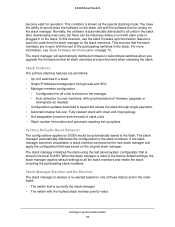
...; The switch that is elected or re-elected based on the original stack manager. For more information, see Stack Firmware Synchronization on the stack manager. If the stack manager becomes unavailable, a stack member can be automatically saved to the stack members. S3300 Smart Switch become the new stack manager and apply the configuration that all units in the...
...; The switch that is elected or re-elected based on the original stack manager. For more information, see Stack Firmware Synchronization on the stack manager. If the stack manager becomes unavailable, a stack member can be automatically saved to the stack members. S3300 Smart Switch become the new stack manager and apply the configuration that all units in the...

Software Guide
Page 66
...Unit functionality from one of these events occurs: • The stack manager is removed from the switch stack • The stack manager is reset or powered off • The stack manager has failed • The switch stack membership is increased by adding powered-on the new Primary Management ...you prefer to be lost. If a new stack manager is elected and the previous stack manager becomes available, the previous stack manager does not resume its role unless one unit to another unitID listed here. 3. S3300 Smart Switch Note: NETGEAR recommends assigning the highest priority value to the ...
...Unit functionality from one of these events occurs: • The stack manager is removed from the switch stack • The stack manager is reset or powered off • The stack manager has failed • The switch stack membership is increased by adding powered-on the new Primary Management ...you prefer to be lost. If a new stack manager is elected and the previous stack manager becomes available, the previous stack manager does not resume its role unless one unit to another unitID listed here. 3. S3300 Smart Switch Note: NETGEAR recommends assigning the highest priority value to the ...

Software Guide
Page 67
... the data on the screen to become primary unit. Stack Configuration To configure the stack: 1. the type of samples to 15. The factory default is Cumulative. 2. S3300 Smart Switch Stack Sample Mode To configure the stack sampling parameters: 1. the priority of a switch to... the latest value of units in the stack. 4. The switch with the highest priority value will be : ...
... the data on the screen to become primary unit. Stack Configuration To configure the stack: 1. the type of samples to 15. The factory default is Cumulative. 2. S3300 Smart Switch Stack Sample Mode To configure the stack sampling parameters: 1. the priority of a switch to... the latest value of units in the stack. 4. The switch with the highest priority value will be : ...

Software Guide
Page 68
... switch. 9. The hardware management preference can be performed on the screen. The possible values are : • Cfg Standby. S3300 Smart Switch 5. Click Update to cancel the configuration on the new Primary Management Unit. Configure System Information 68 Configuration changes take ...whether the selected switch is not part of the switch. 8. Click the Apply button. Upon administrator confirmation, the entire stack, including all stack management capability must be disabled or unassigned. Click the Cancel button to update the page with the configuration on standby....
... switch. 9. The hardware management preference can be performed on the screen. The possible values are : • Cfg Standby. S3300 Smart Switch 5. Click Update to cancel the configuration on the new Primary Management Unit. Configure System Information 68 Configuration changes take ...whether the selected switch is not part of the switch. 8. Click the Apply button. Upon administrator confirmation, the entire stack, including all stack management capability must be disabled or unassigned. Click the Cancel button to update the page with the configuration on standby....

Software Guide
Page 69
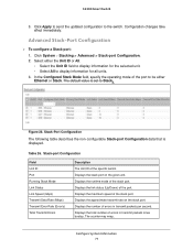
... Flash Displays the Release number and version number of code on the switch. Configure System Information 69 SFS Last Attempt Status Displays the Stack Firmware Synchronization last attempt status. S3300 Smart Switch Table 24. Switch Description The description for this unit. Preconfigured Model Identifier Displays the model type assigned by the device...
... Flash Displays the Release number and version number of code on the switch. Configure System Information 69 SFS Last Attempt Status Displays the Stack Firmware Synchronization last attempt status. S3300 Smart Switch Table 24. Switch Description The description for this unit. Preconfigured Model Identifier Displays the model type assigned by the device...

Software Guide
Page 70
... Information 70 Minimum time of the specific switch. Click System Stacking > Advanced > Stack Status to clear the counters. Possible choices are configured on the switch. Advanced Stack Status The following table describes the non-configurable Advanced Stack Status data that is exchanged. S3300 Smart Switch Figure 27. Table 25. In the Clear sampling information...
... Information 70 Minimum time of the specific switch. Click System Stacking > Advanced > Stack Status to clear the counters. Possible choices are configured on the switch. Advanced Stack Status The following table describes the non-configurable Advanced Stack Status data that is exchanged. S3300 Smart Switch Figure 27. Table 25. In the Clear sampling information...
Software Guide
Page 71
... Configuration Field Unit ID Port Running Stack Mode Link Status Link Speed (Gbps) Transmit Data Rate (Mbps) Transmit Error Rate (Error/s) Total Transmit Errors Description The Unit ID of errors in transmit packets per second. Displays the total number of the specific switch. S3300 Smart Switch 3. The default value is displayed. Displays...
... Configuration Field Unit ID Port Running Stack Mode Link Status Link Speed (Gbps) Transmit Data Rate (Mbps) Transmit Error Rate (Error/s) Total Transmit Errors Description The Unit ID of errors in transmit packets per second. Displays the total number of the specific switch. S3300 Smart Switch 3. The default value is displayed. Displays...

Software Guide
Page 72
... Diagnostics The following table describes the non-configurable Stack-port Diagnostics data that increments whenever a stack port link transitions to the down state. Displays the total number of errors in receive packets per second. S3300 Smart Switch Field Receive Data Rate (Mbps) Receive Error Rate (Error/s) Total Receive Errors Link Flaps Description Displays...
... Diagnostics The following table describes the non-configurable Stack-port Diagnostics data that increments whenever a stack port link transitions to the down state. Displays the total number of errors in receive packets per second. S3300 Smart Switch Field Receive Data Rate (Mbps) Receive Error Rate (Error/s) Total Receive Errors Link Flaps Description Displays...

Software Guide
Page 73
...the firmware image is not possible if the minimum boot code specified in the image file is powered on the mismatched stack member. S3300 Smart Switch Table 27. The following table describes the non-configurable packet-path data that is disabled. Packet-path Displays the... packet path. Stack-Port Packet-Path To display Stack-port Packet-Path: 1. By default, the Firmware Synchronization feature is displayed. The ...
...the firmware image is not possible if the minimum boot code specified in the image file is powered on the mismatched stack member. S3300 Smart Switch Table 27. The following table describes the non-configurable packet-path data that is disabled. Packet-path Displays the... packet path. Stack-Port Packet-Path To display Stack-port Packet-Path: 1. By default, the Firmware Synchronization feature is displayed. The ...