
Hardware Installation Guide
Page 4
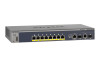
..., boost performance, and increase productivity. Front Panels and LEDs The following : M4100-26G M4100-50G M4100-26-POE M4100-26G-POE M4100-50G-POE+ M4100-50-POE M4100-D10-POE M4100-D12G M4100-12GF M4100-D12G-POE+ M4100-24G-POE+ M4100-12G-POE+ This guide describes hardware installation and basic troubleshooting for each product, visit the NETGEAR website at http://www.netgear.com. The front panel contains LEDs, a Reset button, a USB flash port...
..., boost performance, and increase productivity. Front Panels and LEDs The following : M4100-26G M4100-50G M4100-26-POE M4100-26G-POE M4100-50G-POE+ M4100-50-POE M4100-D10-POE M4100-D12G M4100-12GF M4100-D12G-POE+ M4100-24G-POE+ M4100-12G-POE+ This guide describes hardware installation and basic troubleshooting for each product, visit the NETGEAR website at http://www.netgear.com. The front panel contains LEDs, a Reset button, a USB flash port...

Hardware Installation Guide
Page 10
NETGEAR Managed Switch Console switch Console ports Lock Power adapter connector Figure 14. To reduce the risk of bodily injury, electrical shock, fire, and damage to help protect your system documentation. 10 M4100-D12G-POE+ rear panel AC power connector Safety Instructions Use ...equipment, observe the following precautions. • Observe and follow service markings. - M4100-D10-POE and M4100-D12G rear panels Console port RPS Lock power supply connector Figure 15. M4100-12GF, 24G-POE+, 12G-POE+ rear panel AC power connector Lock Console port Figure 16. Do not service ...
NETGEAR Managed Switch Console switch Console ports Lock Power adapter connector Figure 14. To reduce the risk of bodily injury, electrical shock, fire, and damage to help protect your system documentation. 10 M4100-D12G-POE+ rear panel AC power connector Safety Instructions Use ...equipment, observe the following precautions. • Observe and follow service markings. - M4100-D10-POE and M4100-D12G rear panels Console port RPS Lock power supply connector Figure 15. M4100-12GF, 24G-POE+, 12G-POE+ rear panel AC power connector Lock Console port Figure 16. Do not service ...

Hardware Installation Guide
Page 16
... switch. To install the switch in a Rack Note: The M4100-D10-PoE, M4100-D12G, and M4100-D12G-POE+ are not rack mountable. Keep the following considerations in a rack: 1. To install your switch: • Ambient operating temperature. Therefore, consider installing the equipment in a standard 19-inch rack. NETGEAR Managed Switch Install the Switch You can install the switch...
... switch. To install the switch in a Rack Note: The M4100-D10-PoE, M4100-D12G, and M4100-D12G-POE+ are not rack mountable. Keep the following considerations in a rack: 1. To install your switch: • Ambient operating temperature. Therefore, consider installing the equipment in a standard 19-inch rack. NETGEAR Managed Switch Install the Switch You can install the switch...
Hardware Installation Guide
Page 18
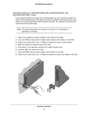
... to the sides of the switch case. Mark the position of the switch. 2. Hammer caps into holes in the wall. 7. NETGEAR Managed Switch Install the Switch on a Wall (M4100-D12G, M4100-D10-PoE, and M4100-D12G-POE+ Only) If you install the switch on a wall in the vertical position, be mounted so that the ports face up...
... to the sides of the switch case. Mark the position of the switch. 2. Hammer caps into holes in the wall. 7. NETGEAR Managed Switch Install the Switch on a Wall (M4100-D12G, M4100-D10-PoE, and M4100-D12G-POE+ Only) If you install the switch on a wall in the vertical position, be mounted so that the ports face up...
Hardware Installation Guide
Page 19
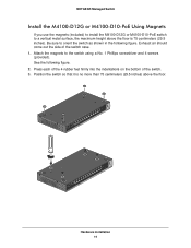
... bottom of the switch case. 1. Exhaust air should come out the side of the switch. 3. NETGEAR Managed Switch Install the M4100-D12G or M4100-D10-PoE Using Magnets If you use the magnets (included) to install the M4100-D12G or M4100-D10-PoE switch to a vertical metal surface, the maximum height above the floor is no more than 75...
... bottom of the switch case. 1. Exhaust air should come out the side of the switch. 3. NETGEAR Managed Switch Install the M4100-D12G or M4100-D10-PoE Using Magnets If you use the magnets (included) to install the M4100-D12G or M4100-D10-PoE switch to a vertical metal surface, the maximum height above the floor is no more than 75...

Hardware Installation Guide
Page 20
...1 of these switches for system operation. The PSE device should light in the following checks: 1. Connect one end of the AC power adapter cable (M4100-DG12 or M4100-D10-PoE) or the AC power cord to a PSE switch. Check the Power LED on self-test (POST). • If the switch passes the test,...front panel of the switch, and the other end to pass data. The switch is working and ready to a grounded three-pronged AC outlet. NETGEAR Managed Switch Check the Installation Before you connect the power cord, select an AC outlet that is not controlled by a wall switch (which can turn...
...1 of these switches for system operation. The PSE device should light in the following checks: 1. Connect one end of the AC power adapter cable (M4100-DG12 or M4100-D10-PoE) or the AC power cord to a PSE switch. Check the Power LED on self-test (POST). • If the switch passes the test,...front panel of the switch, and the other end to pass data. The switch is working and ready to a grounded three-pronged AC outlet. NETGEAR Managed Switch Check the Installation Before you connect the power cord, select an AC outlet that is not controlled by a wall switch (which can turn...

Hardware Installation Guide
Page 28
NETGEAR Managed Switch Table 6. Fast Ethernet switches physical specifications Fast Ethernet Switches M4100-26-POE (FSM7226P) M4100-50-POE (FSM7250P) M4100-D10-POE (FSM5210P) Interface (AutoUplink on all RJ-45 ports) 24 RJ-45 ports for 10/100 Mbps 48 RJ-45 ports for 10/100 Mbps 8 RJ-.../100/1000 Mbps 2 SFP ports for 100/1000 Mbps 2 SFP ports for 100/1000 Mbps 2 SFP ports for 100/1000 Mbps 24 PoE ports 48 IEEE802.3af PoE 8 IEEE802.3af PoE 1 USB type A connector ports ports RS-232 console port 1 USB type A connector 1 USB type A connector 1 USB mini B console RS-232 console port...
NETGEAR Managed Switch Table 6. Fast Ethernet switches physical specifications Fast Ethernet Switches M4100-26-POE (FSM7226P) M4100-50-POE (FSM7250P) M4100-D10-POE (FSM5210P) Interface (AutoUplink on all RJ-45 ports) 24 RJ-45 ports for 10/100 Mbps 48 RJ-45 ports for 10/100 Mbps 8 RJ-.../100/1000 Mbps 2 SFP ports for 100/1000 Mbps 2 SFP ports for 100/1000 Mbps 2 SFP ports for 100/1000 Mbps 24 PoE ports 48 IEEE802.3af PoE 8 IEEE802.3af PoE 1 USB type A connector ports ports RS-232 console port 1 USB type A connector 1 USB type A connector 1 USB mini B console RS-232 console port...
CLI Manual
Page 734
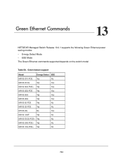
... 13 NETGEAR Managed Switch Release 10.0.1 supports the following Green Ethernet power saving modes: • Energy Detect Mode • EEE Mode The Green Ethernet commands supported depends on the switch model Table 56. Green feature support Model Energy-Detect EEE M4100-D10-POE Yes No M4100-D12G Yes Yes M4100-50G-POE+ Yes Yes M4100-26G-POE Yes Yes M4100...
... 13 NETGEAR Managed Switch Release 10.0.1 supports the following Green Ethernet power saving modes: • Energy Detect Mode • EEE Mode The Green Ethernet commands supported depends on the switch model Table 56. Green feature support Model Energy-Detect EEE M4100-D10-POE Yes No M4100-D12G Yes Yes M4100-50G-POE+ Yes Yes M4100-26G-POE Yes Yes M4100...


