Hardware Installation Guide
Page 3
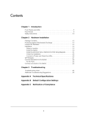
... Package Contents 13 Protecting against Electrostatic Discharge 13 Unpack the Hardware 14 Installation 14 Select a Location 15 Install the Switch 16 Install the M4100-D12G or M4100-D10-PoE Using Magnets 19 Check the Installation 20 Connect to Power and Check the LEDs 20 SFP Modules 21 Connect Equipment to the Switch 22...
... Package Contents 13 Protecting against Electrostatic Discharge 13 Unpack the Hardware 14 Installation 14 Select a Location 15 Install the Switch 16 Install the M4100-D12G or M4100-D10-PoE Using Magnets 19 Check the Installation 20 Connect to Power and Check the LEDs 20 SFP Modules 21 Connect Equipment to the Switch 22...

Hardware Installation Guide
Page 4
1. Front Panels and LEDs The following : M4100-26G M4100-50G M4100-26-POE M4100-26G-POE M4100-50G-POE+ M4100-50-POE M4100-D10-POE M4100-D12G M4100-12GF M4100-D12G-POE+ M4100-24G-POE+ M4100-12G-POE+ This guide describes hardware installation and basic troubleshooting for each product, visit the NETGEAR website at http://www.netgear.com. The front panel contains LEDs, a Reset button, a USB flash port, RJ45 ports, copper (RJ-45)/fiber (SFP...
1. Front Panels and LEDs The following : M4100-26G M4100-50G M4100-26-POE M4100-26G-POE M4100-50G-POE+ M4100-50-POE M4100-D10-POE M4100-D12G M4100-12GF M4100-D12G-POE+ M4100-24G-POE+ M4100-12G-POE+ This guide describes hardware installation and basic troubleshooting for each product, visit the NETGEAR website at http://www.netgear.com. The front panel contains LEDs, a Reset button, a USB flash port, RJ45 ports, copper (RJ-45)/fiber (SFP...

Hardware Installation Guide
Page 5
M4100-26G front panel RJ-45 ports SFP ports Combo Ports Power Fan RPS Reset USB RJ45 SPD/Link/ACT mode: Green = 1G Yellow = 10/100M Blink = ACT LEDs USB port Reset button Figure 2. M4100-50-POE front panel POE ports RJ-45 ports SFP ports 5 M4100-26-POE front panel POE ports RJ-45 ports SFP ports LEDs USB port Reset button Figure 4. M4100-50G front panel RJ-45 ports SFP SPD/Link/ACT mode: Green = Link at 1G Yellow = Link at 100M Blink = ACT SFP ports LEDs USB port Reset button Figure 3. NETGEAR Managed Switch LEDs USB port Reset button Figure 1.
M4100-26G front panel RJ-45 ports SFP ports Combo Ports Power Fan RPS Reset USB RJ45 SPD/Link/ACT mode: Green = 1G Yellow = 10/100M Blink = ACT LEDs USB port Reset button Figure 2. M4100-50-POE front panel POE ports RJ-45 ports SFP ports 5 M4100-26-POE front panel POE ports RJ-45 ports SFP ports LEDs USB port Reset button Figure 4. M4100-50G front panel RJ-45 ports SFP SPD/Link/ACT mode: Green = Link at 1G Yellow = Link at 100M Blink = ACT SFP ports LEDs USB port Reset button Figure 3. NETGEAR Managed Switch LEDs USB port Reset button Figure 1.

Hardware Installation Guide
Page 7
... at 1G Yellow = Link at 100M Blink = ACT SPD/Link/ACT LEDs USB Port Reset button Figure 12. M4100-12G-POE+ front panel PoE (Max 30W per port): Off = No PD Green = PoE Powered Yellow = PoE Fault PoE SPD/Link/ACT RJ45 SPD/Link/ACT mode: Green = 1G Yellow = 10/100M Blink = ACT SPD/Link/...Link/ACT mode: Green = 1G Yellow = 10/100M Blink = ACT LEDs USB port Reset button Figure 9. NETGEAR Managed Switch Power Fan PD MaxPoE Reset USB PoE (Max 30W per port): Off = No PD Green = PoE Powered Yellow = PoE Fault PoE-PD (Port 1, 2): Off = No PSE Green = PSE 30w Yellow = PSE 15.4w RJ45 SPD/Link...
... at 1G Yellow = Link at 100M Blink = ACT SPD/Link/ACT LEDs USB Port Reset button Figure 12. M4100-12G-POE+ front panel PoE (Max 30W per port): Off = No PD Green = PoE Powered Yellow = PoE Fault PoE SPD/Link/ACT RJ45 SPD/Link/ACT mode: Green = 1G Yellow = 10/100M Blink = ACT SPD/Link/...Link/ACT mode: Green = 1G Yellow = 10/100M Blink = ACT LEDs USB port Reset button Figure 9. NETGEAR Managed Switch Power Fan PD MaxPoE Reset USB PoE (Max 30W per port): Off = No PD Green = PoE Powered Yellow = PoE Fault PoE-PD (Port 1, 2): Off = No PSE Green = PSE 30w Yellow = PSE 15.4w RJ45 SPD/Link...

Hardware Installation Guide
Page 8
... connected to off status. Solid green: The fan is supplying power successfully. Note: Only for M4100-26G, 50G, 26-POE, 26G-POE, 50G-POE+, and 50-POE Solid green: PD port 1 is present but RPS has failed. PoE power demand exceeds power available - LED descriptions LED Power Fan RPS PD Max... 802.3at specified power. Blinking yellow: Indicates the PoE MAX LED was active in boot-up stage. Note: Only for another device. Solid yellow: The fan has failed. Off: There is present but has failed. NETGEAR Managed Switch Table 1. Blinking yellow: Packet transmission or...
... connected to off status. Solid green: The fan is supplying power successfully. Note: Only for M4100-26G, 50G, 26-POE, 26G-POE, 50G-POE+, and 50-POE Solid green: PD port 1 is present but RPS has failed. PoE power demand exceeds power available - LED descriptions LED Power Fan RPS PD Max... 802.3at specified power. Blinking yellow: Indicates the PoE MAX LED was active in boot-up stage. Note: Only for another device. Solid yellow: The fan has failed. Off: There is present but has failed. NETGEAR Managed Switch Table 1. Blinking yellow: Packet transmission or...

Hardware Installation Guide
Page 9
NETGEAR Managed Switch Table 1. Solid green: The PSE is occurring on the port. Solid yellow: A valid 100 Mbps SFP module link is established on the port at 1000 Mbps. Blinking yellow: Packet transmission or reception is connected and get 15.4 W power from PSE successfully. M4100-26G, 50G, 26-POE, 26G-POE, 50G-POE+, and 50-POE...a mini USB port (only for M4100-26G, 50G, 26-POE, 26G-POE, 50G-POE+, 50-POE, D12-PoE, and D12G), a redundant power supply connector (only for M4100-26G, 50G, 26-POE, 26G-POE, 50G-POE+, 50-POE, 12GF, 24G-POE+, and 12G-POE+), and a standard AC power receptacle ...
NETGEAR Managed Switch Table 1. Solid green: The PSE is occurring on the port. Solid yellow: A valid 100 Mbps SFP module link is established on the port at 1000 Mbps. Blinking yellow: Packet transmission or reception is connected and get 15.4 W power from PSE successfully. M4100-26G, 50G, 26-POE, 26G-POE, 50G-POE+, and 50-POE...a mini USB port (only for M4100-26G, 50G, 26-POE, 26G-POE, 50G-POE+, 50-POE, D12-PoE, and D12G), a redundant power supply connector (only for M4100-26G, 50G, 26-POE, 26G-POE, 50G-POE+, 50-POE, 12GF, 24G-POE+, and 12G-POE+), and a standard AC power receptacle ...

Hardware Installation Guide
Page 10
... of bodily injury, electrical shock, fire, and damage to help protect your system from potential damage. M4100-D12G-POE+ rear panel AC power connector Safety Instructions Use the following precautions. • Observe and follow service markings. - NETGEAR Managed Switch Console switch Console ports Lock Power adapter connector Figure 14. Do not service any...
... of bodily injury, electrical shock, fire, and damage to help protect your system from potential damage. M4100-D12G-POE+ rear panel AC power connector Safety Instructions Use the following precautions. • Observe and follow service markings. - NETGEAR Managed Switch Console switch Console ports Lock Power adapter connector Figure 14. Do not service any...

Hardware Installation Guide
Page 13
... 2 This chapter explains how to install the hardware for the SFP sockets • Rack-mounting kit • Wall-mounting kit (M4100-D10-POE, M4100-D12G, and M4100-D12G-POE+ only) • Magnetic mounting kit (M4100-D10-POE and M4100-D12G only) • USB console cable with preinstalled software • Power cord • Rubber footpads for tabletop installation •...
... 2 This chapter explains how to install the hardware for the SFP sockets • Rack-mounting kit • Wall-mounting kit (M4100-D10-POE, M4100-D12G, and M4100-D12G-POE+ only) • Magnetic mounting kit (M4100-D10-POE and M4100-D12G only) • USB console cable with preinstalled software • Power cord • Rubber footpads for tabletop installation •...

Hardware Installation Guide
Page 16
... into a rack so that the amount of power strips). • Clearance. To install your switch in a Rack Note: The M4100-D10-PoE, M4100-D12G, and M4100-D12G-POE+ are not rack mountable. Leave enough clearance in front of the rack (about 30 inches) to the branch circuit (for example,...airflow. Consider equipment nameplate ratings when addressing this , ground the rack itself. Keep the following considerations in a standard 19-inch rack. NETGEAR Managed Switch Install the Switch You can install the switch on a flat surface or in mind as you install your switch: • ...
... into a rack so that the amount of power strips). • Clearance. To install your switch in a Rack Note: The M4100-D10-PoE, M4100-D12G, and M4100-D12G-POE+ are not rack mountable. Leave enough clearance in front of the rack (about 30 inches) to the branch circuit (for example,...airflow. Consider equipment nameplate ratings when addressing this , ground the rack itself. Keep the following considerations in a standard 19-inch rack. NETGEAR Managed Switch Install the Switch You can install the switch on a flat surface or in mind as you install your switch: • ...

Hardware Installation Guide
Page 17
NETGEAR Managed Switch 2. Use the provided Phillips head screws to fasten the brackets to secure the switch in the rack. Tighten the screws with a No. 1 Phillips screwdriver to secure each bracket to fasten each bracket. 4. Use two pan-head screws with nylon washers to the rack. 5. M4100-24G-POE+ Mounting bracket 3. Align the bracket and rack holes. Hardware Installation 17 Tighten the screws with a No. 2 Phillips screwdriver to the sides of the switch.
NETGEAR Managed Switch 2. Use the provided Phillips head screws to fasten the brackets to secure the switch in the rack. Tighten the screws with a No. 1 Phillips screwdriver to secure each bracket to fasten each bracket. 4. Use two pan-head screws with nylon washers to the rack. 5. M4100-24G-POE+ Mounting bracket 3. Align the bracket and rack holes. Hardware Installation 17 Tighten the screws with a No. 2 Phillips screwdriver to the sides of the switch.
Hardware Installation Guide
Page 18
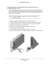
NETGEAR Managed Switch Install the Switch on a Wall (M4100-D12G, M4100-D10-PoE, and M4100-D12G-POE+ Only) If you install the switch on the wall. 5. Note: The switch should have a minimum of 5 inches (130 millimeters) of the switch. 2. Attach the supplied ...
NETGEAR Managed Switch Install the Switch on a Wall (M4100-D12G, M4100-D10-PoE, and M4100-D12G-POE+ Only) If you install the switch on the wall. 5. Note: The switch should have a minimum of 5 inches (130 millimeters) of the switch. 2. Attach the supplied ...
Hardware Installation Guide
Page 19
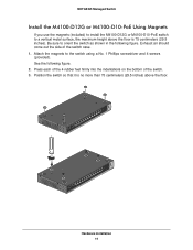
NETGEAR Managed Switch Install the M4100-D12G or M4100-D10-PoE Using Magnets If you use the magnets (included) to install the M4100-D12G or M4100-D10-PoE switch to a vertical metal surface, the maximum height above the floor is no more than 75 centimeters (29.5 inches) above the floor. Attach the magnets ...
NETGEAR Managed Switch Install the M4100-D12G or M4100-D10-PoE Using Magnets If you use the magnets (included) to install the M4100-D12G or M4100-D10-PoE switch to a vertical metal surface, the maximum height above the floor is no more than 75 centimeters (29.5 inches) above the floor. Attach the magnets ...

Hardware Installation Guide
Page 20
... Installation 20 Be sure that all cables are not damaged and will get power from an RPS. These switches can turn off switch. NETGEAR Managed Switch Check the Installation Before you connect the power cord, select an AC outlet that is not controlled by a wall switch (which... a power-on self-test (POST). • If the switch passes the test, the LED turns green. Note: The M4100-26G, 50G, 26-PoE, 26G-PoE, 50-PoE+, 50G-PoE, 12GF, 24G-POE+, 12G-POE+ can provide full power to these switches to a grounded three-pronged AC outlet. Supported RPS models are the RPS5412 and RPS4000...
... Installation 20 Be sure that all cables are not damaged and will get power from an RPS. These switches can turn off switch. NETGEAR Managed Switch Check the Installation Before you connect the power cord, select an AC outlet that is not controlled by a wall switch (which... a power-on self-test (POST). • If the switch passes the test, the LED turns green. Note: The M4100-26G, 50G, 26-PoE, 26G-PoE, 50-PoE+, 50G-PoE, 12GF, 24G-POE+, 12G-POE+ can provide full power to these switches to a grounded three-pronged AC outlet. Supported RPS models are the RPS5412 and RPS4000...

Hardware Installation Guide
Page 21
... optical transceiver modules that are UL approved and that it supports IEEE802.3at. Check the PoE device specification to a IEEE802.3af PoE device. SFP Modules SFP modules (sold separately) can be inserted directly into the switch port. 2. NETGEAR Managed Switch • If the POST fails, the Power LED blinks yellow. Note: If the... IEEE 802.3u 100Base-FX standard To insert an SFP module into the connector. For more information, see Troubleshooting on the front panel of the M4100-D12G and M4100-D12G-POE+ blinks green, port 1 is good. Hardware Installation 21
... optical transceiver modules that are UL approved and that it supports IEEE802.3at. Check the PoE device specification to a IEEE802.3af PoE device. SFP Modules SFP modules (sold separately) can be inserted directly into the switch port. 2. NETGEAR Managed Switch • If the POST fails, the Power LED blinks yellow. Note: If the... IEEE 802.3u 100Base-FX standard To insert an SFP module into the connector. For more information, see Troubleshooting on the front panel of the M4100-D12G and M4100-D12G-POE+ blinks green, port 1 is good. Hardware Installation 21
Hardware Installation Guide
Page 26
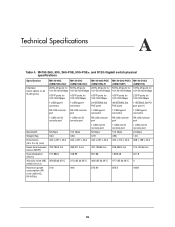
... D12G Gigabit switch physical specifications Specification Interface (Auto Uplink on all RJ-45 ports) M4100-26G M4100-50G M4100-26G-POE M4100-50G-POE+ M4100-D12G (GSM7224v2h2) (GSM7248v2h2) (GSM7226LP) (GSM7248P) (GSM5212) 26 RJ-45 ports for 50 RJ-45 ports, 26 RJ-45 ports for 50 RJ-45 .../1000 Mbps 4 SFP ports for 100/1000 Mbps 2 SFP ports for 100/1000 Mbps 1 USB type A connector 1 USB type A connector 24 IEEE802.3at PoE ports 48 IEEE802.3at PoE ports 1 IEEE802.3at PD port (port 1) RS-232 console port RS-232 console port 1 USB type A connector 1 USB type A connector 1 USB type...
... D12G Gigabit switch physical specifications Specification Interface (Auto Uplink on all RJ-45 ports) M4100-26G M4100-50G M4100-26G-POE M4100-50G-POE+ M4100-D12G (GSM7224v2h2) (GSM7248v2h2) (GSM7226LP) (GSM7248P) (GSM5212) 26 RJ-45 ports for 50 RJ-45 ports, 26 RJ-45 ports for 50 RJ-45 .../1000 Mbps 4 SFP ports for 100/1000 Mbps 2 SFP ports for 100/1000 Mbps 1 USB type A connector 1 USB type A connector 24 IEEE802.3at PoE ports 48 IEEE802.3at PoE ports 1 IEEE802.3at PD port (port 1) RS-232 console port RS-232 console port 1 USB type A connector 1 USB type A connector 1 USB type...
Hardware Installation Guide
Page 27
...A connector RS-232 console port 1 USB mini B console port 48 Gbps 4.368 440 x 257 x 43.2 M4100-D12G-POE+ M4100-12G-POE+ (GSM5212P) (GSM7212P) M4100-12GF (GSM7212F) 12 RJ-45 ports for 10/100/1000 Mbps 12 RJ-45 ports for 10/100/1000 Mbps...port 1 USB mini B console port 12 RJ-45 ports for 10/100/1000 Mbps 12 SFP ports for 100/1000 Mbps 4 IEEE802.3at PoE ports 1 USB type A connector RS-232 console port 1 USB mini B console port 24 Gbps 24 Gbps 24 Gbps 2.596 4.021 3.... AC mode 0dB with PD mode 167.00 50.3 452.00 48 161.00 Technical Specifications 27 NETGEAR Managed Switch Table 5.
...A connector RS-232 console port 1 USB mini B console port 48 Gbps 4.368 440 x 257 x 43.2 M4100-D12G-POE+ M4100-12G-POE+ (GSM5212P) (GSM7212P) M4100-12GF (GSM7212F) 12 RJ-45 ports for 10/100/1000 Mbps 12 RJ-45 ports for 10/100/1000 Mbps...port 1 USB mini B console port 12 RJ-45 ports for 10/100/1000 Mbps 12 SFP ports for 100/1000 Mbps 4 IEEE802.3at PoE ports 1 USB type A connector RS-232 console port 1 USB mini B console port 24 Gbps 24 Gbps 24 Gbps 2.596 4.021 3.... AC mode 0dB with PD mode 167.00 50.3 452.00 48 161.00 Technical Specifications 27 NETGEAR Managed Switch Table 5.

Hardware Installation Guide
Page 28
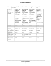
NETGEAR Managed Switch Table 6. Fast Ethernet switches physical specifications Fast Ethernet Switches M4100-26-POE (FSM7226P) M4100-50-POE (FSM7250P) M4100-D10-POE (FSM5210P) Interface (AutoUplink on all RJ-45 ports) 24 RJ-45 ports for 10/100 Mbps 48 RJ-45 ports for 10/100 Mbps 8 RJ-.../100/1000 Mbps 2 SFP ports for 100/1000 Mbps 2 SFP ports for 100/1000 Mbps 2 SFP ports for 100/1000 Mbps 24 PoE ports 48 IEEE802.3af PoE 8 IEEE802.3af PoE 1 USB type A connector ports ports RS-232 console port 1 USB type A connector 1 USB type A connector 1 USB mini B console RS-232 console port...
NETGEAR Managed Switch Table 6. Fast Ethernet switches physical specifications Fast Ethernet Switches M4100-26-POE (FSM7226P) M4100-50-POE (FSM7250P) M4100-D10-POE (FSM5210P) Interface (AutoUplink on all RJ-45 ports) 24 RJ-45 ports for 10/100 Mbps 48 RJ-45 ports for 10/100 Mbps 8 RJ-.../100/1000 Mbps 2 SFP ports for 100/1000 Mbps 2 SFP ports for 100/1000 Mbps 2 SFP ports for 100/1000 Mbps 24 PoE ports 48 IEEE802.3af PoE 8 IEEE802.3af PoE 1 USB type A connector ports ports RS-232 console port 1 USB type A connector 1 USB type A connector 1 USB mini B console RS-232 console port...
CLI Manual
Page 1
ProSafe Managed Switch Command Line Interface (CLI) User Manual 350 East Plumeria Drive San Jose, CA 95134 USA February 2013 202-11166-02 1.0 10.0.1 M7100-24X M4100-24G-POE+ M4100-26G M4100-26-POE M4100-26G-POE M4100-50G M4100-50-POE M4100-50G-POE+ M4100-12GF M4100-12G-POE+ M4100-D12G M4100-D10-POE M4100-D12G-POE+
ProSafe Managed Switch Command Line Interface (CLI) User Manual 350 East Plumeria Drive San Jose, CA 95134 USA February 2013 202-11166-02 1.0 10.0.1 M7100-24X M4100-24G-POE+ M4100-26G M4100-26-POE M4100-26G-POE M4100-50G M4100-50-POE M4100-50G-POE+ M4100-12GF M4100-12G-POE+ M4100-D12G M4100-D10-POE M4100-D12G-POE+

CLI Manual
Page 5
ProSafe M4100 and M7100 Managed Switches Chapter 6 IPv6 Commands Tunnel Interface Commands 356 IPv6 Routing Commands 357 OSPFv3 Commands 380 OSPFv3 Graceful Restart Commands 411 DHCPv6 Commands ... Access Control List (ACL) Commands 484 Time Range Commands for Time-Based ACLs 488 AutoVOIP 490 iSCSI Commands 494 Chapter 9 Power over Ethernet (PoE) Commands About PoE 501 PoE Commands 502 Chapter 10 Utility Commands Auto Install Commands 513 Dual Image Commands 515 System Information and Statistics Commands 517 Logging Commands 534 Email...
ProSafe M4100 and M7100 Managed Switches Chapter 6 IPv6 Commands Tunnel Interface Commands 356 IPv6 Routing Commands 357 OSPFv3 Commands 380 OSPFv3 Graceful Restart Commands 411 DHCPv6 Commands ... Access Control List (ACL) Commands 484 Time Range Commands for Time-Based ACLs 488 AutoVOIP 490 iSCSI Commands 494 Chapter 9 Power over Ethernet (PoE) Commands About PoE 501 PoE Commands 502 Chapter 10 Utility Commands Auto Install Commands 513 Dual Image Commands 515 System Information and Statistics Commands 517 Logging Commands 534 Email...
CLI Manual
Page 8
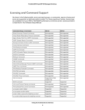
... groups, or commands, require a license and some are available from your VAR or NETGEAR authorized e-commerce portal. Command Group or Command Router Discovery Protocol Commands Virtual Router Redundancy ... Multicast Forwarder Commands IPv6 PIM Commands IPv6 MLD Commands IPv6 MLD-Proxy Commands PoE Commands MVR Commands Link Local Protocol Filtering Commands Priority-Based Flow Control Commands...random-detect random-detect exponential weighting-constant no random-detect exponential weighting-constant M4100 Not supported Not supported Not supported Not supported Not supported Not supported ...
... groups, or commands, require a license and some are available from your VAR or NETGEAR authorized e-commerce portal. Command Group or Command Router Discovery Protocol Commands Virtual Router Redundancy ... Multicast Forwarder Commands IPv6 PIM Commands IPv6 MLD Commands IPv6 MLD-Proxy Commands PoE Commands MVR Commands Link Local Protocol Filtering Commands Priority-Based Flow Control Commands...random-detect random-detect exponential weighting-constant no random-detect exponential weighting-constant M4100 Not supported Not supported Not supported Not supported Not supported Not supported ...

