Shared access to the Internet for multiple VLANs - No routing
Page 1
The procedure described can apply to all the Smart Switches and VPN Firewall with new Web Interface (defined as the one with the Menus appearing horizontally on multiple VLANs using MultiHoming This document describes how to a port...8 Testing the scenario ...10 Further notes...10 Table of managing multiple IP subnets (... Multi-Homing (extract from the DGFV338 Help page 3 Physical Setup ...3 Logical Setup ...3 DGFV338 Primary LAN ...4 DGFV338 Secondary VLAN ...5 Smartswitch VLAN creation ...6 Assigning Port membership to a VLAN 7 Assigning a PVID to obtain Internet access on top).
The procedure described can apply to all the Smart Switches and VPN Firewall with new Web Interface (defined as the one with the Menus appearing horizontally on multiple VLANs using MultiHoming This document describes how to a port...8 Testing the scenario ...10 Further notes...10 Table of managing multiple IP subnets (... Multi-Homing (extract from the DGFV338 Help page 3 Physical Setup ...3 Logical Setup ...3 DGFV338 Primary LAN ...4 DGFV338 Secondary VLAN ...5 Smartswitch VLAN creation ...6 Assigning Port membership to a VLAN 7 Assigning a PVID to obtain Internet access on top).
Shared access to the Internet for multiple VLANs - No routing
Page 2
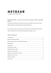
... changes, additions, and moves to be created per unit, device or via logical connection/combination • Broadcast and Multicast traffic is required 24 Port 10/100/1000 Mbps Smart Switch 1 3 5 7 9 11 13 15 17 19 21 23 LINK/ACT SPD Green = 100Mbps Yellow = 10Mbps FD X 2 4 6 8 10 12 14 16 18 20 22 ... 17 19 21 23T 14 16 18 20 22 24T 23F 24F SFP LINK SFP LINK MODEL GS724T A uto™ U pli nk Fa c to r y Defaults ProSafe VPN Wireless ADSL Gateway MODEL DGFV 338 PWR TEST IN TERN ET 10 0 D SL LINK/ACT LOC AL 10 0 1 2 3 4 5 6 7 8 W LAN Link/A CT VLANs allow ...
... changes, additions, and moves to be created per unit, device or via logical connection/combination • Broadcast and Multicast traffic is required 24 Port 10/100/1000 Mbps Smart Switch 1 3 5 7 9 11 13 15 17 19 21 23 LINK/ACT SPD Green = 100Mbps Yellow = 10Mbps FD X 2 4 6 8 10 12 14 16 18 20 22 ... 17 19 21 23T 14 16 18 20 22 24T 23F 24F SFP LINK SFP LINK MODEL GS724T A uto™ U pli nk Fa c to r y Defaults ProSafe VPN Wireless ADSL Gateway MODEL DGFV 338 PWR TEST IN TERN ET 10 0 D SL LINK/ACT LOC AL 10 0 1 2 3 4 5 6 7 8 W LAN Link/A CT VLANs allow ...
Shared access to the Internet for multiple VLANs - No routing
Page 6
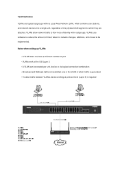
Smartswitch VLAN creation VLAN are created on the Smartswitch via the GUI (Switching, VLAN, Basic, VLAN configuration). To complete the scenarion 3 VLAN will need to complete the scenario (VLAN20, 30, 40) The two pictures below show the creation of VLAN20, and the results of the creation of all the VLAN required to be created.
Smartswitch VLAN creation VLAN are created on the Smartswitch via the GUI (Switching, VLAN, Basic, VLAN configuration). To complete the scenarion 3 VLAN will need to complete the scenario (VLAN20, 30, 40) The two pictures below show the creation of VLAN20, and the results of the creation of all the VLAN required to be created.
Shared access to the Internet for multiple VLANs - No routing
Page 7
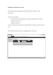
Assigning Port membership to browse through the options just continuosly click on all the ports. Tagged membership (T) In order to a VLAN Port membership can be using the U (Untagged) option on the gray box until the correct one is set. For this scenarion we will be assigned via the GUI (Switching, VLAN, Advanced , VLAN membership). Three options are available: - Untagged membership (U) - No membership (no simbol appearing in the gray box underneath the port number) -
Assigning Port membership to browse through the options just continuosly click on all the ports. Tagged membership (T) In order to a VLAN Port membership can be using the U (Untagged) option on the gray box until the correct one is set. For this scenarion we will be assigned via the GUI (Switching, VLAN, Advanced , VLAN membership). Three options are available: - Untagged membership (U) - No membership (no simbol appearing in the gray box underneath the port number) -
Shared access to the Internet for multiple VLANs - No routing
Page 8
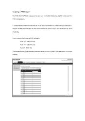
In our scenario the following PVID will apply: Ports 0/5 - 0/6 (PVID 20) Ports 0/7 - 0/8 (PVID 30) Port 0/9 (PVID 40) The below pictures show how after clicking on apply (for all 3 VLANs PVID) we obtain the correct settings: Assigning a PVID to a port The PVID (Port VLAN ID) is member of the VLAN IDs). It is important that the PVID matches the VLAN a port is assigned to multiple VLANs (in which case the PVID must still be set and be unique, but can match any of , unless such port belongs to each port via the GUI (Switching, VLAN, Advanced, Port PVID configuration).
In our scenario the following PVID will apply: Ports 0/5 - 0/6 (PVID 20) Ports 0/7 - 0/8 (PVID 30) Port 0/9 (PVID 40) The below pictures show how after clicking on apply (for all 3 VLANs PVID) we obtain the correct settings: Assigning a PVID to a port The PVID (Port VLAN ID) is member of the VLAN IDs). It is important that the PVID matches the VLAN a port is assigned to multiple VLANs (in which case the PVID must still be set and be unique, but can match any of , unless such port belongs to each port via the GUI (Switching, VLAN, Advanced, Port PVID configuration).
Shared access to the Internet for multiple VLANs - No routing
Page 10
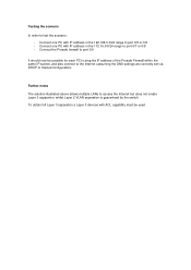
... full Layer 3 separation a Layer 3 devices with IP address in the 192.168.0.0/24 range to port 0/7 or 0/8 - Connect one PC with ACL capability must be possible for each PC to ping the IP address of the Prosafe Firewall within the same IP subnet, and also connect to the Internet (assuming the DNS... the scenario: - Testing the scenario In order to access the Internet but does not create Layer 3 separation, whilst Layer 2 VLAN separation is guaranteed by the switch.
... full Layer 3 separation a Layer 3 devices with IP address in the 192.168.0.0/24 range to port 0/7 or 0/8 - Connect one PC with ACL capability must be possible for each PC to ping the IP address of the Prosafe Firewall within the same IP subnet, and also connect to the Internet (assuming the DNS... the scenario: - Testing the scenario In order to access the Internet but does not create Layer 3 separation, whilst Layer 2 VLAN separation is guaranteed by the switch.

GS7xxTS Hardware manual
Page 2
...the regulations may occur due to certain restrictions. Bestätigung des Herstellers/Importeurs Es wird hiermit bestätigt, daß das Smart Switch gemäß der im BMPT-AmtsblVfg 243/1991 und Vfg 46/1992 aufgeführten Bestimmungen entstört ist. Support Information ...however, be subject to the use or application of product and software upgrades. Testsender) kann jedoch gewissen Beschränkungen unterliegen. FullManual. NETGEAR does not assume any liability that the GS700TS Smart Switch has been suppressed in the BMPT-AmtsblVfg 243/1991 and Vfg 46/1992.
...the regulations may occur due to certain restrictions. Bestätigung des Herstellers/Importeurs Es wird hiermit bestätigt, daß das Smart Switch gemäß der im BMPT-AmtsblVfg 243/1991 und Vfg 46/1992 aufgeführten Bestimmungen entstört ist. Support Information ...however, be subject to the use or application of product and software upgrades. Testsender) kann jedoch gewissen Beschränkungen unterliegen. FullManual. NETGEAR does not assume any liability that the GS700TS Smart Switch has been suppressed in the BMPT-AmtsblVfg 243/1991 and Vfg 46/1992.

GS7xxTS Hardware manual
Page 3
... near a radio or TV receiver, it may cause undesired operation. FCC Declaration Of Conformity We NETGEAR, Inc., 4500 Great America Parkway, Santa Clara, CA 95054, declare under our sole responsibility that the model GS700TS Smart Switch with Gigabit Ports complies with the limits for correct handling. FCC Radio Frequency Interference Warnings & Instructions This equipment has...
... near a radio or TV receiver, it may cause undesired operation. FCC Declaration Of Conformity We NETGEAR, Inc., 4500 Great America Parkway, Santa Clara, CA 95054, declare under our sole responsibility that the model GS700TS Smart Switch with Gigabit Ports complies with the limits for correct handling. FCC Radio Frequency Interference Warnings & Instructions This equipment has...

GS7xxTS Hardware manual
Page 4
...NETGEAR, Inc., could void the user's right to operate the equipment. Product and Publication Details Model Number: Publication Date: Product Family: Product Name: Home or Business Product: Language: Publication Part Number: Publication Version Number: GS700TS November 2007 Smart Switch GS700TS Smart Switch Business English 202-10332-01 1.0 iv v1.0, November 2007 GS700TS Smart Switch with Gigabit Ports... This digital apparatus (GS700TS Smart Switch with FCC Standards FOR HOME OR OFFICE USE Modifications made to Comply with Gigabit Ports) does not exceed the Class B limits for help.
...NETGEAR, Inc., could void the user's right to operate the equipment. Product and Publication Details Model Number: Publication Date: Product Family: Product Name: Home or Business Product: Language: Publication Part Number: Publication Version Number: GS700TS November 2007 Smart Switch GS700TS Smart Switch Business English 202-10332-01 1.0 iv v1.0, November 2007 GS700TS Smart Switch with Gigabit Ports... This digital apparatus (GS700TS Smart Switch with FCC Standards FOR HOME OR OFFICE USE Modifications made to Comply with Gigabit Ports) does not exceed the Class B limits for help.

GS7xxTS Hardware manual
Page 5
...2 Installation Step 1: Preparing the Site 2-29 Step 2: Installing the Switch 2-30 Installing the Switch on a Flat Surface 2-30 Installing the Switch in a Rack 2-30 Step 3: Checking the Installation 2-31 Step 4: Connecting Devices to the Switch 2-32 Step 5: Installing an SFP GBIC Module 2-32 Step 6: ...7: Applying AC Power 2-34 Step 8: Managing the Switch through a Web Browser or the PC Utility for Initial Configuration ...2-35 Chapter 3 Physical Description Front and Back Panel Configuration 3-19 GS724TS Front and Back Panels 3-19 GS748TS Front and Back Panels 3-20 v v1.0, November ...
...2 Installation Step 1: Preparing the Site 2-29 Step 2: Installing the Switch 2-30 Installing the Switch on a Flat Surface 2-30 Installing the Switch in a Rack 2-30 Step 3: Checking the Installation 2-31 Step 4: Connecting Devices to the Switch 2-32 Step 5: Installing an SFP GBIC Module 2-32 Step 6: ...7: Applying AC Power 2-34 Step 8: Managing the Switch through a Web Browser or the PC Utility for Initial Configuration ...2-35 Chapter 3 Physical Description Front and Back Panel Configuration 3-19 GS724TS Front and Back Panels 3-19 GS748TS Front and Back Panels 3-20 v v1.0, November ...
GS7xxTS Hardware manual
Page 6
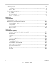
... ...3-22 System LEDs ...3-22 Device Hardware Interfaces 3-23 RJ-45 Ports ...3-23 SFP GBIC Module 3-24 Factory Defaults Button 3-24 Appendix A Troubleshooting Troubleshooting Chart A-1 Additional Troubleshooting Suggestions A-2 Network Adapter Cards A-2 Configuration ...A-2 Switch Integrity ...A-2 Auto-negotiation ...A-3 Appendix B Technical Specifications Network Protocol and Standards Compatibility B-1 Management ...B-1 Interface ...B-1 LEDs ...B-1 Performance Specifications B-2 Power Supply ...B-2 Physical Specifications...
... ...3-22 System LEDs ...3-22 Device Hardware Interfaces 3-23 RJ-45 Ports ...3-23 SFP GBIC Module 3-24 Factory Defaults Button 3-24 Appendix A Troubleshooting Troubleshooting Chart A-1 Additional Troubleshooting Suggestions A-2 Network Adapter Cards A-2 Configuration ...A-2 Switch Integrity ...A-2 Auto-negotiation ...A-3 Appendix B Technical Specifications Network Protocol and Standards Compatibility B-1 Management ...B-1 Interface ...B-1 LEDs ...B-1 Performance Specifications B-2 Power Supply ...B-2 Physical Specifications...
GS7xxTS Hardware manual
Page 7
..., CDs, URL names User input Screen text, file and server names, extensions, commands, IP addresses • Formats. Failure to install, configure and troubleshoot the smart switch. The NETGEAR® GS700TS Installation Manual describes how to take heed of importance or special interest. ix v1.0, November 2007 About This Guide Congratulations on the purchase... or death. This manual uses the following paragraphs: • Typographical Conventions. Warning: Ignoring this manual is a safety warning. The information in this type of the NETGEAR Smart Switch.
..., CDs, URL names User input Screen text, file and server names, extensions, commands, IP addresses • Formats. Failure to install, configure and troubleshoot the smart switch. The NETGEAR® GS700TS Installation Manual describes how to take heed of importance or special interest. ix v1.0, November 2007 About This Guide Congratulations on the purchase... or death. This manual uses the following paragraphs: • Typographical Conventions. Warning: Ignoring this manual is a safety warning. The information in this type of the NETGEAR Smart Switch.
GS7xxTS Hardware manual
Page 8
... requirements. • Printing a Page in the chapter you were viewing opens in the manual. • The button accesses the full NETGEAR, Inc. Each page in the HTML version of the chapter you want to print. Use the Print button on the browser toolbar to... these specifications: Product Version Manual Publication Date GS700TS Smart Switch November 2007 Note: Product updates are available on the NETGEAR, Inc. GS700TS Hardware Installation Guide • Scope. This manual is described in a browser window. - web ...
... requirements. • Printing a Page in the chapter you were viewing opens in the manual. • The button accesses the full NETGEAR, Inc. Each page in the HTML version of the chapter you want to print. Use the Print button on the browser toolbar to... these specifications: Product Version Manual Publication Date GS700TS Smart Switch November 2007 Note: Product updates are available on the NETGEAR, Inc. GS700TS Hardware Installation Guide • Scope. This manual is described in a browser window. - web ...
GS7xxTS Hardware manual
Page 10
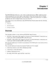
... 1 Introduction The NETGEAR Smart Switch is for the following NETGEAR Smart Switches: • GS724TS - To simplify installation, the switch is shipped ready for use a device as an introduction to the GS700TS Smart Switch and provides the following information: • Overview • Switch Features • ...Gigabit connectivity to each other with four additional SFP combo fiber ports. • GS748TS - This product offers support for 48 ports of 10/100/1000 BaseT of which four are Combo ports with four additional SFP combo fiber ports. For example: • Connecting switches...
... 1 Introduction The NETGEAR Smart Switch is for the following NETGEAR Smart Switches: • GS724TS - To simplify installation, the switch is shipped ready for use a device as an introduction to the GS700TS Smart Switch and provides the following information: • Overview • Switch Features • ...Gigabit connectivity to each other with four additional SFP combo fiber ports. • GS748TS - This product offers support for 48 ports of 10/100/1000 BaseT of which four are Combo ports with four additional SFP combo fiber ports. For example: • Connecting switches...
GS7xxTS Hardware manual
Page 11
... ports can view the switch's many features and use them in a simple and intuitive manner. In addition, all RJ-45 ports operate...mode. The NETGEAR Smart Switch can provide 2000 Mbps throughput. With full-duplex enabled, the switch port connected to the... server or PC can be free-standing, or rack mounted in half- This capability makes the switch ideal for fiber connections using SFP GBIC modules. The GS700TS Smart Switch...prioritization. GS700TS Hardware Installation Guide The GS700TS Smart Switch also provides the benefit of administrative management with...
... ports can view the switch's many features and use them in a simple and intuitive manner. In addition, all RJ-45 ports operate...mode. The NETGEAR Smart Switch can provide 2000 Mbps throughput. With full-duplex enabled, the switch port connected to the... server or PC can be free-standing, or rack mounted in half- This capability makes the switch ideal for fiber connections using SFP GBIC modules. The GS700TS Smart Switch...prioritization. GS700TS Hardware Installation Guide The GS700TS Smart Switch also provides the benefit of administrative management with...

GS7xxTS Hardware manual
Page 12
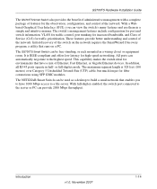
...four 10/100/1000M auto-sensing Giga switching ports on each device. GS700TS Hardware Installation Guide Figure 1-1 Switch Features The following list identifies the key features of the NETGEAR Smart Switch. • 24/48 RJ-45 10/100/1000M auto-sensing Giga switching ports. • Four Small Form-factor ...Pluggable (SFP) GBIC slots, which function as combo ports. Combo ports are single ports with fiber port taking priority if both devices are...
...four 10/100/1000M auto-sensing Giga switching ports on each device. GS700TS Hardware Installation Guide Figure 1-1 Switch Features The following list identifies the key features of the NETGEAR Smart Switch. • 24/48 RJ-45 10/100/1000M auto-sensing Giga switching ports. • Four Small Form-factor ...Pluggable (SFP) GBIC slots, which function as combo ports. Combo ports are single ports with fiber port taking priority if both devices are...
GS7xxTS Hardware manual
Page 13
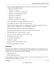
... information table. Stacking Stacking provides multiple switch management through which the stack is managed. IEEE 802.3i, (10Base-T) - IEEE 802.3u (100Base-TX, 100Base-FX) - IEEE 802.3z (1000Base-X) - Up to 192 10/100/1000 ports are accessed through a single IP address...or can operate as if all 10/100/1000 Mbps ports. • Store-and-Forward transmission to remove bad packets from the following IEEE standards: - GS700TS Hardware Installation Guide • The devices support full Netgear Smart Switch functionality and provide full compatibility with the following : &#...
... information table. Stacking Stacking provides multiple switch management through which the stack is managed. IEEE 802.3i, (10Base-T) - IEEE 802.3u (100Base-TX, 100Base-FX) - IEEE 802.3z (1000Base-X) - Up to 192 10/100/1000 ports are accessed through a single IP address...or can operate as if all 10/100/1000 Mbps ports. • Store-and-Forward transmission to remove bad packets from the following IEEE standards: - GS700TS Hardware Installation Guide • The devices support full Netgear Smart Switch functionality and provide full compatibility with the following : &#...
GS7xxTS Hardware manual
Page 14
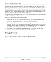
... unit runs as slave stack members, and assigned a unique Unit ID. All other devices are assigned unit IDs of 1 and 2. Switch software is downloaded separately for the configuration. • Master-Backup - If a MasterBackup becomes the Master Unit, another Master-Backup will not... the Stack-Master role. Package Contents Figure 1-2 shows the package contents of the NETGEAR Smart Switch 1-17 v1.0, November 2007 Introduction GS700TS Hardware Installation Guide During the Stacking setup, the switches will auto-select one of the following modes: • Stand-alone - The backup...
... unit runs as slave stack members, and assigned a unique Unit ID. All other devices are assigned unit IDs of 1 and 2. Switch software is downloaded separately for the configuration. • Master-Backup - If a MasterBackup becomes the Master Unit, another Master-Backup will not... the Stack-Master role. Package Contents Figure 1-2 shows the package contents of the NETGEAR Smart Switch 1-17 v1.0, November 2007 Introduction GS700TS Hardware Installation Guide During the Stacking setup, the switches will auto-select one of the following modes: • Stand-alone - The backup...
GS7xxTS Hardware manual
Page 15
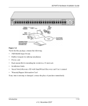
GS700TS Hardware Installation Guide Figure 1-2 Verify that the package contains the following: • NETGEAR Smart Switch • Rubber footpads for tabletop installation • Power cord • Rack-mount Kit for installing the switch in a 19-inch rack • Installation Guide • Smart Switch Resource CD with SmartWizard Discovery and User's manual • Warranty/Support Information Card If any item is missing or damaged, contact the place of purchase immediately. Introduction v1.0, November 2007 1-18
GS700TS Hardware Installation Guide Figure 1-2 Verify that the package contains the following: • NETGEAR Smart Switch • Rubber footpads for tabletop installation • Power cord • Rack-mount Kit for installing the switch in a 19-inch rack • Installation Guide • Smart Switch Resource CD with SmartWizard Discovery and User's manual • Warranty/Support Information Card If any item is missing or damaged, contact the place of purchase immediately. Introduction v1.0, November 2007 1-18

GS7xxTS Hardware manual
Page 16
...(48.3-centimeter) EIA standard equipment rack that allows access to the front panel RJ-45 ports, the ability to view the front panel LEDs, and easy safe access access to the Switch Step 5: Installing an SFP GBIC Module Step 6: Installing a Device Step 7: Applying AC Power Step 8: Managing the Switch ...through a Web Browser or the PC Utility for your NETGEAR Smart Switch. The...
...(48.3-centimeter) EIA standard equipment rack that allows access to the front panel RJ-45 ports, the ability to view the front panel LEDs, and easy safe access access to the Switch Step 5: Installing an SFP GBIC Module Step 6: Installing a Device Step 7: Applying AC Power Step 8: Managing the Switch ...through a Web Browser or the PC Utility for your NETGEAR Smart Switch. The...

