GS7xxTS Hardware manual
Page 21
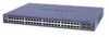
... 2-4 The device is operational. When applying power, the Power LED on the switch's front panel is by a wall switch, which can turn off power to the power receptacle on stacking see the NETGEAR Smart Switch User Guide. The method of the AC power adapter cable to apply AC power. 1. Before connecting the power cord, select a grounded 3-pronged...
... 2-4 The device is operational. When applying power, the Power LED on the switch's front panel is by a wall switch, which can turn off power to the power receptacle on stacking see the NETGEAR Smart Switch User Guide. The method of the AC power adapter cable to apply AC power. 1. Before connecting the power cord, select a grounded 3-pronged...
GS7xxTS Hardware manual
Page 27
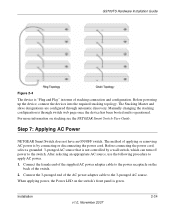
... of the attached device. This technology allows attaching devices to the switch and is occurring on the Down stacking port. • Off - When inserting a cable into an RJ-45 port, the switch automatically ascertains the maximum speed (10 or 100 or 1000 Mbps) ...Designation Indicates the Down stacking port LED designations • Off - Power is a straight-through or crossover cables. When inserting a cable into the switch's RJ-45 port, the switch automatically: • Senses whether the cable is disconnected. • Solid Green - Indicates the Down stacking port link is not ...
... of the attached device. This technology allows attaching devices to the switch and is occurring on the Down stacking port. • Off - When inserting a cable into an RJ-45 port, the switch automatically ascertains the maximum speed (10 or 100 or 1000 Mbps) ...Designation Indicates the Down stacking port LED designations • Off - Power is a straight-through or crossover cables. When inserting a cable into the switch's RJ-45 port, the switch automatically: • Senses whether the cable is disconnected. • Solid Green - Indicates the Down stacking port link is not ...
GS7xxTS User Manual
Page 44
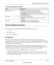
... is operating as a backup to send traffic. The Ring topology connects all copper cables. A Chain topology 3-9 Managing System Settings v1.0, June 2009 Manages the stacking configuration for all stack members. • Secondary Master - GS700TS Smart Switch Software Administration Manual • Inter-unit Stacking Link Failure • Unit Insertion • Removal of the following modes: • Standalone...
... is operating as a backup to send traffic. The Ring topology connects all copper cables. A Chain topology 3-9 Managing System Settings v1.0, June 2009 Manages the stacking configuration for all stack members. • Secondary Master - GS700TS Smart Switch Software Administration Manual • Inter-unit Stacking Link Failure • Unit Insertion • Removal of the following modes: • Standalone...
GS7xxTS User Manual
Page 221
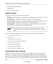
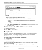
... this screen, including: • The stacking mode • The stacking cables • The Unit ID numbering To restore stacking defaults, press the reset button on the front panel of your device. Select the confirmation box to the factory defaults: 1. The stacking defaults are : - 1, 2, 3, 4, 5, 6 - Reboots the stacking member associated with the switch. GS700TS Smart Switch Software Administration Manual Figure 8-1 The...
... this screen, including: • The stacking mode • The stacking cables • The Unit ID numbering To restore stacking defaults, press the reset button on the front panel of your device. Select the confirmation box to the factory defaults: 1. The stacking defaults are : - 1, 2, 3, 4, 5, 6 - Reboots the stacking member associated with the switch. GS700TS Smart Switch Software Administration Manual Figure 8-1 The...
