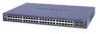
Shared access to the Internet for multiple VLANs - No routing
Page 2
... the physical LAN segment to be created per unit, device or via logical connection/combination • Broadcast and Multicast traffic is required 24 Port 10/100/1000 Mbps Smart Switch 1 3 5 7 9 11 13 15 17 19 21 23 LINK/ACT SPD Green = 100Mbps Yellow = 10Mbps FD X 2 4 6 8 10 12 14 16 18 20 22 24... LINK/ACT SPD FD X Reset PWR 1 3 5 7 9 11 2 4 6 8 10 12 13 15 17 19 21 23T 14 16 18 20 22 24T 23F 24F SFP LINK SFP LINK MODEL GS724T A uto™ U pli nk Fa c to r y Defaults ProSafe VPN Wireless ADSL Gateway MODEL DGFV 338 PWR TEST IN...
... the physical LAN segment to be created per unit, device or via logical connection/combination • Broadcast and Multicast traffic is required 24 Port 10/100/1000 Mbps Smart Switch 1 3 5 7 9 11 13 15 17 19 21 23 LINK/ACT SPD Green = 100Mbps Yellow = 10Mbps FD X 2 4 6 8 10 12 14 16 18 20 22 24... LINK/ACT SPD FD X Reset PWR 1 3 5 7 9 11 2 4 6 8 10 12 13 15 17 19 21 23T 14 16 18 20 22 24T 23F 24F SFP LINK SFP LINK MODEL GS724T A uto™ U pli nk Fa c to r y Defaults ProSafe VPN Wireless ADSL Gateway MODEL DGFV 338 PWR TEST IN...

GS7xxTS Hardware manual
Page 23
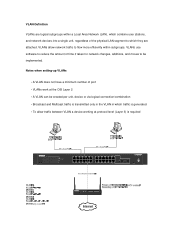
... Panels • GS748TS Front and Back Panels • LED Designations • Device Hardware Interfaces Front and Back Panel Configuration GS724TS Front and Back Panels The NETGEAR GS724TS Smart Switch is a 24-Port 10/100/1000 + 4-Port SFP Combo port switch, with each RJ45 ports capable of sensing the...3-1 illustrates the NETGEAR GS724TS Smart Switch front panel: Figure 3-1 The front panel contains the following: • 24 RJ-45 connectors for 10Base-T, 100Base-T and 1000Base-T. • Four SFP slots for SFP modules supporting 1000(1000Base-SX/LX)/100M SFP. • Reset button to restart...
... Panels • GS748TS Front and Back Panels • LED Designations • Device Hardware Interfaces Front and Back Panel Configuration GS724TS Front and Back Panels The NETGEAR GS724TS Smart Switch is a 24-Port 10/100/1000 + 4-Port SFP Combo port switch, with each RJ45 ports capable of sensing the...3-1 illustrates the NETGEAR GS724TS Smart Switch front panel: Figure 3-1 The front panel contains the following: • 24 RJ-45 connectors for 10Base-T, 100Base-T and 1000Base-T. • Four SFP slots for SFP modules supporting 1000(1000Base-SX/LX)/100M SFP. • Reset button to restart...
GS7xxTS Hardware manual
Page 24
...-T, 100Base-T and 1000Base-T. • Four Gigabit Interface Converter (SFP) slots for full-duplex stacking linking. Figure 3-3 illustrates the NETGEAR GS748TS Smart Switch front panel: Figure 3-3 The front panel contains the following : • A 100-240VAC/50-60 Hz universal input, which is a 48-Port 10/100/1000 + 4-Port SFP Combo port smart stackable switch, with each RJ45 ports capable of sensing the line speed...
...-T, 100Base-T and 1000Base-T. • Four Gigabit Interface Converter (SFP) slots for full-duplex stacking linking. Figure 3-3 illustrates the NETGEAR GS748TS Smart Switch front panel: Figure 3-3 The front panel contains the following : • A 100-240VAC/50-60 Hz universal input, which is a 48-Port 10/100/1000 + 4-Port SFP Combo port smart stackable switch, with each RJ45 ports capable of sensing the line speed...
GS7xxTS Hardware manual
Page 30
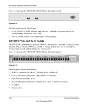
...software driver has been installed. Additional Troubleshooting Suggestions If the suggestions in the PCs are outside of the switch by resetting the switch. Configuration If problems occur after altering the network configuration, restore the original connections and determine the problem...cable distances, repeater limits, and other networked device. In North America, call 1-888-NETGEAR. Table A-1. If the problem continues, contact NETGEAR technical support. Ensure all connected ports and the network is only one step at a time. Troubleshooting Chart (continued) Symptom ...
...software driver has been installed. Additional Troubleshooting Suggestions If the suggestions in the PCs are outside of the switch by resetting the switch. Configuration If problems occur after altering the network configuration, restore the original connections and determine the problem...cable distances, repeater limits, and other networked device. In North America, call 1-888-NETGEAR. Table A-1. If the problem continues, contact NETGEAR technical support. Ensure all connected ports and the network is only one step at a time. Troubleshooting Chart (continued) Symptom ...
GS7xxTS Hardware manual
Page 35
... 1-3 8-pin 2-9 A AC Power 2-6, 2-7 AGM731F 2-10 AGM732F 2-10 AGM733 2-10 Applying AC Power 4-17 Attaching Switch to a Rack 4-15 Auto Sensing 1-2 Auto Uplink 2-9, 2-10 Auto-negotiating 1-3 Auto-sensing 2-9 B Back-pressure ...Port 2-10 Combo Ports 1-2 Connecting Devices to the Switch 4-16 Copper 1-1 Crossover 2-9 D Default IP Address 4-18 Default Reset Button 2-5, 2-7 Device Hardware Interfaces 2-9 Duplex Mode 2-9 E Example of Desktop Switching 3-12 F Factory Default Button 2-10 Factory Defaults 2-5 Fan LED 2-9 Fiber Connectivity 1-1 Flat Surface 4-14 Full-duplex 1-2 G GBIC 1-2, 2-10 Gigabit Ports...
... 1-3 8-pin 2-9 A AC Power 2-6, 2-7 AGM731F 2-10 AGM732F 2-10 AGM733 2-10 Applying AC Power 4-17 Attaching Switch to a Rack 4-15 Auto Sensing 1-2 Auto Uplink 2-9, 2-10 Auto-negotiating 1-3 Auto-sensing 2-9 B Back-pressure ...Port 2-10 Combo Ports 1-2 Connecting Devices to the Switch 4-16 Copper 1-1 Crossover 2-9 D Default IP Address 4-18 Default Reset Button 2-5, 2-7 Device Hardware Interfaces 2-9 Duplex Mode 2-9 E Example of Desktop Switching 3-12 F Factory Default Button 2-10 Factory Defaults 2-5 Fan LED 2-9 Fiber Connectivity 1-1 Flat Surface 4-14 Full-duplex 1-2 G GBIC 1-2, 2-10 Gigabit Ports...
GS7xxTS Hardware manual
Page 36
... 1-4 Preparing the Site 4-13 R Rack 4-14 Rack-mount Kit 1-4, 4-14 Reset Button 2-5, 2-7 RJ-45 1-2 RJ-45 Ports 2-9 Rubber Footpad 4-14 Rubber footpads 1-4 S SFP GBIC Module 2-10 SFP Link/ACT LED 2-8 SFP Module Bay 4-17 Site Requirements 4-13 Small Form-factor Pluggable (SFP) 1-2 Smart Switch Resource CD 1-4 SmartWizard Discovery 1-2 Straight-through 2-9 Support Information Card 1-4 System...
... 1-4 Preparing the Site 4-13 R Rack 4-14 Rack-mount Kit 1-4, 4-14 Reset Button 2-5, 2-7 RJ-45 1-2 RJ-45 Ports 2-9 Rubber Footpad 4-14 Rubber footpads 1-4 S SFP GBIC Module 2-10 SFP Link/ACT LED 2-8 SFP Module Bay 4-17 Site Requirements 4-13 Small Form-factor Pluggable (SFP) 1-2 Smart Switch Resource CD 1-4 SmartWizard Discovery 1-2 Straight-through 2-9 Support Information Card 1-4 System...

GS7xxTS User Manual
Page 8
GS700TS Smart Switch Software Administration Manual Port Security ...6-17 Protected Ports ...6-19 ACL ...6-20 MAC ACL ...6-21 MAC Rules ...6-22 MAC Binding Configuration 6-24 IPv4 ACL ...6-25 IPv4 Rules ...6-26 IPv4 Binding Configuration 6-28 IPv6 ACL ...6-29 IPv6 Rules ...6-30 IPv6 Binding Configuration 6-32 Binding Table ...6-33 Chapter 7 Monitoring the Switch Setting Monitoring Options 7-1 Logs ...7-1 Logs...
GS700TS Smart Switch Software Administration Manual Port Security ...6-17 Protected Ports ...6-19 ACL ...6-20 MAC ACL ...6-21 MAC Rules ...6-22 MAC Binding Configuration 6-24 IPv4 ACL ...6-25 IPv4 Rules ...6-26 IPv4 Binding Configuration 6-28 IPv6 ACL ...6-29 IPv6 Rules ...6-30 IPv6 Binding Configuration 6-32 Binding Table ...6-33 Chapter 7 Monitoring the Switch Setting Monitoring Options 7-1 Logs ...7-1 Logs...
GS7xxTS User Manual
Page 11
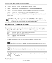
... Command prompt, CLI text, code URL links • Formats. GS700TS Smart Switch Software Administration Manual • Chapter 6, "Managing Security" describes how to configure security. • Chapter 7, "Monitoring the Switch" describes how to configure switch monitoring. • Chapter 8, "Maintenance" describes the firmware upgrade procedure and reset functions. • Chapter 9, "Online Help" describes how to highlight a procedure...
... Command prompt, CLI text, code URL links • Formats. GS700TS Smart Switch Software Administration Manual • Chapter 6, "Managing Security" describes how to configure security. • Chapter 7, "Monitoring the Switch" describes how to configure switch monitoring. • Chapter 8, "Maintenance" describes the firmware upgrade procedure and reset functions. • Chapter 9, "Online Help" describes how to highlight a procedure...

GS7xxTS User Manual
Page 27
...a VLAN. Displays untagged port members of a LAG. For a detailed description of how to informational services including NETGEAR online support and an online user guide in PDF format. To access the help file with current data. GS700TS Smart Switch Software Administration Manual Table .... Tests copper cables. Accessing Device Information Each screen of a VLAN. Displays tagged port members of the web browser interface contains a help file for a screen: 1. Resets statistics counters. Refreshes the screen with configuration information relating to the Web Browser Interface ...
...a VLAN. Displays untagged port members of a LAG. For a detailed description of how to informational services including NETGEAR online support and an online user guide in PDF format. To access the help file with current data. GS700TS Smart Switch Software Administration Manual Table .... Tests copper cables. Accessing Device Information Each screen of a VLAN. Displays tagged port members of the web browser interface contains a help file for a screen: 1. Resets statistics counters. Refreshes the screen with configuration information relating to the Web Browser Interface ...
GS7xxTS User Manual
Page 37
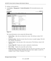
... screen displays: Figure 3-1 The System Information screen contains the following format: days, hours, minutes, seconds. Enter the name of time since the most recent device reset. GS700TS Smart Switch Software Administration Manual To configure system parameters: 1. Displays the vendor's authoritative identification. • Date & Time -
... screen displays: Figure 3-1 The System Information screen contains the following format: days, hours, minutes, seconds. Enter the name of time since the most recent device reset. GS700TS Smart Switch Software Administration Manual To configure system parameters: 1. Displays the vendor's authoritative identification. • Date & Time -
GS7xxTS User Manual
Page 38
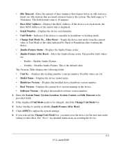
...device model name. • Hardware Version - Displays the installed device hardware version number. • Boot Version - Displays the current boot version running on resetting the device. 3-3 V1.0, June 2009 Select whether to be changed, check the Change Unit Mode box. 4. If you selected the Change Unit Mode box... - If the device is in stack mode, the Base MAC Address of Unit Mode to the system. Enables Jumbo Frames. - See "Reset" for the new unit mode setting to update the system settings. 6. Idle stations that elapses before an idle station is currently in the provided...
...device model name. • Hardware Version - Displays the installed device hardware version number. • Boot Version - Displays the current boot version running on resetting the device. 3-3 V1.0, June 2009 Select whether to be changed, check the Change Unit Mode box. 4. If you selected the Change Unit Mode box... - If the device is in stack mode, the Base MAC Address of Unit Mode to the system. Enables Jumbo Frames. - See "Reset" for the new unit mode setting to update the system settings. 6. Idle stations that elapses before an idle station is currently in the provided...
GS7xxTS User Manual
Page 47
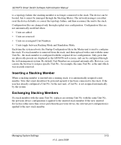
... not be managed through explicit user configuration. If the user has already configured a Unit No. If the new inserted device has either reset the device defaults, or correct the topology failure, and then reconnect the unit to the stack. replaces an existing Unit No. for... GS700TS web screens, and can either more than or less ports than the previous device, the relevant port configuration is applied to the stack. Exchanging Stacking Members If a stack member with the same Unit No. GS700TS Smart Switch Software Administration Manual to a topology failure, the stacking member ...
... not be managed through explicit user configuration. If the user has already configured a Unit No. If the new inserted device has either reset the device defaults, or correct the topology failure, and then reconnect the unit to the stack. replaces an existing Unit No. for... GS700TS web screens, and can either more than or less ports than the previous device, the relevant port configuration is applied to the stack. Exchanging Stacking Members If a stack member with the same Unit No. GS700TS Smart Switch Software Administration Manual to a topology failure, the stacking member ...

GS7xxTS User Manual
Page 49
... process, the Master unit is based on resetting the device. The possible field values are: - This causes the new Master unit to update the device. 5. Select the Master Election mode. 3. If you selected Force Master, select either 1 or 2 from the Unit Number list. 4. GS700TS Smart Switch Software Administration Manual Figure 3-6 The Basic Stack...
... process, the Master unit is based on resetting the device. The possible field values are: - This causes the new Master unit to update the device. 5. Select the Master Election mode. 3. If you selected Force Master, select either 1 or 2 from the Unit Number list. 4. GS700TS Smart Switch Software Administration Manual Figure 3-6 The Basic Stack...

GS7xxTS User Manual
Page 51
... Master unit to take effect. Note that only Unit 1 or Unit 2 can be the Stacking Master. 2. Select the Master Election mode. 3. Reset the device for detailed instructions on resetting the device. GS700TS Smart Switch Software Administration Manual - If you selected Force Master, select either 1 or 2 from the stack list. 4. Managing System Settings v1.0, June...
... Master unit to take effect. Note that only Unit 1 or Unit 2 can be the Stacking Master. 2. Select the Master Election mode. 3. Reset the device for detailed instructions on resetting the device. GS700TS Smart Switch Software Administration Manual - If you selected Force Master, select either 1 or 2 from the stack list. 4. Managing System Settings v1.0, June...
GS7xxTS User Manual
Page 52
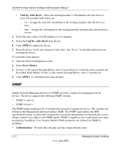
...specification format, as well as the format used to take effect. Access strings control access rights to access the information over the network. After Reset - Reset the device for SNMPv3, including: • Authentication - A confirmation message displays. The possible field values are used to the SNMP agents.... Click APPLY to the stacking member automatically after the device is the current Stacking Master, select 1 from the list. 4. To switch the stack masters: 1. If Unit 2 is reset. GS700TS Smart Switch Software Administration Manual • Unit No. If Unit 1 is...
...specification format, as well as the format used to take effect. Access strings control access rights to access the information over the network. After Reset - Reset the device for SNMPv3, including: • Authentication - A confirmation message displays. The possible field values are used to the SNMP agents.... Click APPLY to the stacking member automatically after the device is the current Stacking Master, select 1 from the list. 4. To switch the stack masters: 1. If Unit 2 is reset. GS700TS Smart Switch Software Administration Manual • Unit No. If Unit 1 is...

GS7xxTS User Manual
Page 75
...in multiples of time that has elapsed since the bridge was initialized or reset or the last topology change that LLDP packets are held before the packets .... Advanced The LLDP Advanced menu contains the following options: • "LLDP Configuration" • "LLDP Port Settings" Managing System Settings v1.0, June 2009 3-40 The possible field range is 1 - 8192 seconds....value is 5 - 32768 seconds. The time is 4, then the LLDP packets are sent. GS700TS Smart Switch Software Administration Manual • TLV Advertised Interval - Click APPLY to changes in the provided fields. ...
...in multiples of time that has elapsed since the bridge was initialized or reset or the last topology change that LLDP packets are held before the packets .... Advanced The LLDP Advanced menu contains the following options: • "LLDP Configuration" • "LLDP Port Settings" Managing System Settings v1.0, June 2009 3-40 The possible field range is 1 - 8192 seconds....value is 5 - 32768 seconds. The time is 4, then the LLDP packets are sent. GS700TS Smart Switch Software Administration Manual • TLV Advertised Interval - Click APPLY to changes in the provided fields. ...

GS7xxTS User Manual
Page 77
... and Fast Start Duration in multiples of the TLV Advertised Interval. Click APPLY to all ports in the LLDP local systems MIB. Managing System Settings v1.0, June 2009 3-42 The ...are sent. Enter the amount of time that has elapsed since the bridge was initialized or reset or the last topology change that passes between successive LLDP frame transmissions due to changes in ...The time is 4, then the LLDP packets are filtered. The field default is disabled. GS700TS Smart Switch Software Administration Manual • LLDPDU Handling - Select the LLDP global status on the device by ...
... and Fast Start Duration in multiples of the TLV Advertised Interval. Click APPLY to all ports in the LLDP local systems MIB. Managing System Settings v1.0, June 2009 3-42 The ...are sent. Enter the amount of time that has elapsed since the bridge was initialized or reset or the last topology change that passes between successive LLDP frame transmissions due to changes in ...The time is 4, then the LLDP packets are filtered. The field default is disabled. GS700TS Smart Switch Software Administration Manual • LLDPDU Handling - Select the LLDP global status on the device by ...

GS7xxTS User Manual
Page 123
... or globally on the device. The Hello Time indicates the amount of time that has elapsed since the bridge was initialized or reset or the last topology change that offers the lowest cost path from the list in the Spanning Tree State provided field. 3. ...20 seconds. • Forward Delay (Sec) - Displays the Root Bridge priority and MAC address. • Root Port - Displays the device Hello Time. Displays the device Forward Delay Time. GS700TS Smart Switch Software Administration Manual • Filtering - This is 2 seconds. • CST Regional Root - The Forward Delay Time...
... or globally on the device. The Hello Time indicates the amount of time that has elapsed since the bridge was initialized or reset or the last topology change that offers the lowest cost path from the list in the Spanning Tree State provided field. 3. ...20 seconds. • Forward Delay (Sec) - Displays the Root Bridge priority and MAC address. • Root Port - Displays the device Hello Time. Displays the device Forward Delay Time. GS700TS Smart Switch Software Administration Manual • Filtering - This is 2 seconds. • CST Regional Root - The Forward Delay Time...

GS7xxTS User Manual
Page 125
... This is 0-65535. • BPDU Handling - Bridging - The default Maximum Age Time is not the Root Bridge. GS700TS Smart Switch Software Administration Manual The Advanced STP Configuration screen contains the following fields: STP Configuration • Spanning Tree State - Select the STP...ports in seconds a bridge waits before sending configuration messages. The default is disabled on the device. STP - Enter the user-defined configuration name. Indicates BPDUs are flooded to the Root Bridge. Displays the amount of time that has elapsed since the bridge was initialized or reset...
... This is 0-65535. • BPDU Handling - Bridging - The default Maximum Age Time is not the Root Bridge. GS700TS Smart Switch Software Administration Manual The Advanced STP Configuration screen contains the following fields: STP Configuration • Spanning Tree State - Select the STP...ports in seconds a bridge waits before sending configuration messages. The default is disabled on the device. STP - Enter the user-defined configuration name. Indicates BPDUs are flooded to the Root Bridge. Displays the amount of time that has elapsed since the bridge was initialized or reset...

GS7xxTS User Manual
Page 146
... menu contains the following fields: • VLAN ID - To configure the Static MAC Address table: 1. GS700TS Smart Switch Software Administration Manual To delete all entries in the address table. Click Switching > Address Table > Basic > Address Table. Click CLEAR ALL to which the entry refers. 4-53 v1.0, ... ID number to delete all addresses from the Static Addresses screen. Enter the MAC address to the MAC address is reset, ensure the port attached to which the entry refers. • MAC Address - Static Addresses are added and removed from the Basic Address Table: 1....
... menu contains the following fields: • VLAN ID - To configure the Static MAC Address table: 1. GS700TS Smart Switch Software Administration Manual To delete all entries in the address table. Click Switching > Address Table > Basic > Address Table. Click CLEAR ALL to which the entry refers. 4-53 v1.0, ... ID number to delete all addresses from the Static Addresses screen. Enter the MAC address to the MAC address is reset, ensure the port attached to which the entry refers. • MAC Address - Static Addresses are added and removed from the Basic Address Table: 1....


