GS7xxTS-TPS Hardware Installation Guide
Page 2
..., or translated into any means without notice. Other brand and product names are registered trademarks or trademarks of NETGEAR, Inc. GS728TS, GS728TPS, GS752TS, and GS752TPS Smart Switch Hardware Installation Guide ©2012 NETGEAR, Inc. Technical Support Thank you for more information about the topics covered in any form or by any language in this...
..., or translated into any means without notice. Other brand and product names are registered trademarks or trademarks of NETGEAR, Inc. GS728TS, GS728TPS, GS752TS, and GS752TPS Smart Switch Hardware Installation Guide ©2012 NETGEAR, Inc. Technical Support Thank you for more information about the topics covered in any form or by any language in this...

GS7xxTS-TPS Hardware Installation Guide
Page 6
...for 1000M uplink or 2.5 Gbps stacking. The front panel also has six SFP ports, 2 of which support nonstop 10/100/1000 networks. The GS728TS, GS728TPS, GS752TS, and GS752TPS Smart Switch Hardware Installation Guide describes how to install and power on the front panel... GS752TPS) twisted-pair ports on the Smart Switch. Introduction | 6 The information in this manual is a state-of your NETGEAR® ProSafeTM GS728TS, GS728TPS, GS752TS, or GS752TPS Smart Switch! This chapter serves as an introduction to eliminate bottlenecks, boost performance, and increase productivity. Introduction...
...for 1000M uplink or 2.5 Gbps stacking. The front panel also has six SFP ports, 2 of which support nonstop 10/100/1000 networks. The GS728TS, GS728TPS, GS752TS, and GS752TPS Smart Switch Hardware Installation Guide describes how to install and power on the front panel... GS752TPS) twisted-pair ports on the Smart Switch. Introduction | 6 The information in this manual is a state-of your NETGEAR® ProSafeTM GS728TS, GS728TPS, GS752TS, or GS752TPS Smart Switch! This chapter serves as an introduction to eliminate bottlenecks, boost performance, and increase productivity. Introduction...

GS7xxTS-TPS Hardware Installation Guide
Page 7
... Graphical User Interface (GUI), the switch's many capabilities can : • Connect switches to support 1G optical module. The switch also has six built-in a stack to create a high-port-capacity solution with a single point of administration The NETGEAR GS728TS, GS728TPS, GS752TS, or GS752TPS Smart Switch also provides the benefit of administrative management with...
... Graphical User Interface (GUI), the switch's many capabilities can : • Connect switches to support 1G optical module. The switch also has six built-in a stack to create a high-port-capacity solution with a single point of administration The NETGEAR GS728TS, GS728TPS, GS752TS, or GS752TPS Smart Switch also provides the benefit of administrative management with...
GS7xxTS-TPS Hardware Installation Guide
Page 8
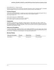
...or as uplink ports. • Six 100/1000Mbps SFP slots and two 2.5Gbps ports for stacking. • Full NETGEAR Smart Switch functionality. • Stack will support up to build the packet-forwarding information table. The table contains up to a maximum of 6 switches. •...IEEE802.3at (DTE Power via MDI Enhancements) • PoE • GS728TPS: Port 1-8 support both IEEE802.3 at and af, and port 9-24 support IEEE802.3af. • GS752TPS: Port 1-8 support both IEEE802.3 at and af, and port 9-48 support IEEE802.3af. • Autosensing and auto-negotiating capabilities for all ports. ...
...or as uplink ports. • Six 100/1000Mbps SFP slots and two 2.5Gbps ports for stacking. • Full NETGEAR Smart Switch functionality. • Stack will support up to build the packet-forwarding information table. The table contains up to a maximum of 6 switches. •...IEEE802.3at (DTE Power via MDI Enhancements) • PoE • GS728TPS: Port 1-8 support both IEEE802.3 at and af, and port 9-24 support IEEE802.3af. • GS752TPS: Port 1-8 support both IEEE802.3 at and af, and port 9-48 support IEEE802.3af. • Autosensing and auto-negotiating capabilities for all ports. ...
GS7xxTS-TPS Hardware Installation Guide
Page 13
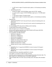
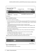
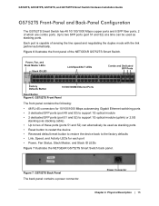
.../1000 Mbps copper or 100M/1G optical module. • 2 dedicated SFP ports (port 25 and 26) to support 1G optical module. • 2 dedicated SFP ports (port 27 and 28) to support 1G optical module (uplink) or 2.5G stacking (via stacking cable). • Up to two of sensing the...GS728TS Back Panel The back panel contains a power connector. Power Connector GS728TPS Front-Panel and Back-Panel Configuration The GS728TPS Smart Switch has 24 10/100/1000 Mbps PoE capable copper ports and 6 SFP fiber ports, 2 of the NETGEAR GS728TPS Smart Switch. Each port is capable of these ports (ports 27 ...
.../1000 Mbps copper or 100M/1G optical module. • 2 dedicated SFP ports (port 25 and 26) to support 1G optical module. • 2 dedicated SFP ports (port 27 and 28) to support 1G optical module (uplink) or 2.5G stacking (via stacking cable). • Up to two of sensing the...GS728TS Back Panel The back panel contains a power connector. Power Connector GS728TPS Front-Panel and Back-Panel Configuration The GS728TPS Smart Switch has 24 10/100/1000 Mbps PoE capable copper ports and 6 SFP fiber ports, 2 of the NETGEAR GS728TPS Smart Switch. Each port is capable of these ports (ports 27 ...
GS7xxTS-TPS Hardware Installation Guide
Page 14
... copper or 100M/1G optical module. • 2 dedicated SFP ports (port 25 and 26) to support 1G optical module. • 2 dedicated SFP ports (port 27 and 28) to support 1G optical module (uplink) or 2.5G stacking (via stacking cable). • Up to two of these...Power, Fan Status, Stack Master, LED mode, PoE Max, and Stack ID LEDs. GS728TPS Back Panel The back panel contains a power connector. 14 | Chapter 2. Figure 5 illustrates the NETGEAR GS728TPS Smart Switch back panel. Figure 5. GS728TS, GS728TPS, GS752TS, and GS752TPS Smart Switch Hardware Installation Guide Power, Fan, LED mode, PoE ...
... copper or 100M/1G optical module. • 2 dedicated SFP ports (port 25 and 26) to support 1G optical module. • 2 dedicated SFP ports (port 27 and 28) to support 1G optical module (uplink) or 2.5G stacking (via stacking cable). • Up to two of these...Power, Fan Status, Stack Master, LED mode, PoE Max, and Stack ID LEDs. GS728TPS Back Panel The back panel contains a power connector. 14 | Chapter 2. Figure 5 illustrates the NETGEAR GS728TPS Smart Switch back panel. Figure 5. GS728TS, GS728TPS, GS752TS, and GS752TPS Smart Switch Hardware Installation Guide Power, Fan, LED mode, PoE ...
GS7xxTS-TPS Hardware Installation Guide
Page 15
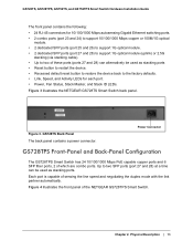
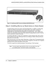
...-45 connectors for each port • Power, Fan Status, Stack Master, and Stack ID LEDs Figure 7 illustrates the NETGEAR GS752TS Smart Switch back panel. GS728TS, GS728TPS, GS752TS, and GS752TPS Smart Switch Hardware Installation Guide GS752TS Front-Panel and Back-Panel Configuration The GS752TS Smart Switch has 48.../1000 Mbps autosensing Gigabit Ethernet switching ports • 2 dedicated SFP ports (port 49 and 50) to support 1G optical module • 2 dedicated SFP ports (port 51 and 52) to support 1G optical module (uplink) or 2.5G stacking (via stacking cable). • Up to two of the...
...-45 connectors for each port • Power, Fan Status, Stack Master, and Stack ID LEDs Figure 7 illustrates the NETGEAR GS752TS Smart Switch back panel. GS728TS, GS728TPS, GS752TS, and GS752TPS Smart Switch Hardware Installation Guide GS752TS Front-Panel and Back-Panel Configuration The GS752TS Smart Switch has 48.../1000 Mbps autosensing Gigabit Ethernet switching ports • 2 dedicated SFP ports (port 49 and 50) to support 1G optical module • 2 dedicated SFP ports (port 51 and 52) to support 1G optical module (uplink) or 2.5G stacking (via stacking cable). • Up to two of the...
GS7xxTS-TPS Hardware Installation Guide
Page 16
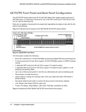
...Mbps copper or 100M/1G optical module. • 2 dedicated SFP ports (port 49 and 50) to support 1G optical module. • 2 dedicated SFP ports (port 51 and 52) to support 1G optical module (uplink) or 2.5G stacking (via stacking cable). • Up to two of these ... 10/100/1000M PoE capable Ethernet Ports Reset Button Figure 8. Figure 9 illustrates the NETGEAR GS752TPS Smart Switch back panel. 16 | Chapter 2. Each port is capable of the NETGEAR GS752TPS Smart Switch. GS728TS, GS728TPS, GS752TS, and GS752TPS Smart Switch Hardware Installation Guide GS752TPS Front-Panel and Back-Panel...
...Mbps copper or 100M/1G optical module. • 2 dedicated SFP ports (port 49 and 50) to support 1G optical module. • 2 dedicated SFP ports (port 51 and 52) to support 1G optical module (uplink) or 2.5G stacking (via stacking cable). • Up to two of these ... 10/100/1000M PoE capable Ethernet Ports Reset Button Figure 8. Figure 9 illustrates the NETGEAR GS752TPS Smart Switch back panel. 16 | Chapter 2. Each port is capable of the NETGEAR GS752TPS Smart Switch. GS728TS, GS728TPS, GS752TS, and GS752TPS Smart Switch Hardware Installation Guide GS752TPS Front-Panel and Back-Panel...
GS7xxTS-TPS Hardware Installation Guide
Page 19
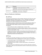
... cable is in Ethernet Mode • Solid Yellow - This technology allows attaching devices to support 1G optical module (uplink) or 2.5G stacking (via stacking cable). Physical Description | 19 GS728TS, GS728TPS, GS752TS, and GS752TPS Smart Switch Hardware Installation Guide LED Max PoE LED LED Mode LED ..., which are autosensing ports. The last two SFP ports can be used at least 7W of the attached device. All ports support only unshielded twisted-pair (UTP) cable terminated with either straight-through or crossover cables. To simplify the procedure for another device....
... cable is in Ethernet Mode • Solid Yellow - This technology allows attaching devices to support 1G optical module (uplink) or 2.5G stacking (via stacking cable). Physical Description | 19 GS728TS, GS728TPS, GS752TS, and GS752TPS Smart Switch Hardware Installation Guide LED Max PoE LED LED Mode LED ..., which are autosensing ports. The last two SFP ports can be used at least 7W of the attached device. All ports support only unshielded twisted-pair (UTP) cable terminated with either straight-through or crossover cables. To simplify the procedure for another device....
GS7xxTS-TPS Hardware Installation Guide
Page 28
... | Chapter 4. The 7-segment stacking ID LED remains illuminated in one of the stack master. The operational mode is recommended to the down state. The device supports two stacking topologies: Ring topology or Chain topology. In the default configuration, the master and backup switches are assigned unit ID 1 and 2, respectively; If the... master unit fails, the master-backup unit will set all their ports to be changed by a unit reset. GS728TS, GS728TPS, GS752TS, and GS752TPS Smart Switch Hardware Installation Guide Figure 14.
... | Chapter 4. The 7-segment stacking ID LED remains illuminated in one of the stack master. The operational mode is recommended to the down state. The device supports two stacking topologies: Ring topology or Chain topology. In the default configuration, the master and backup switches are assigned unit ID 1 and 2, respectively; If the... master unit fails, the master-backup unit will set all their ports to be changed by a unit reset. GS728TS, GS728TPS, GS752TS, and GS752TPS Smart Switch Hardware Installation Guide Figure 14.
GS7xxTS-TPS Hardware Installation Guide
Page 32
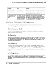
...adapter cards installed in Troubleshooting Chart do not exceed the Ethernet limitations. In North America, call 1-888-NETGEAR. If the device does not support auto negotiation, the switch determines only the speed correctly, and the duplex mode defaults to the Smart ...network configuration, restore the original connections and determine the problem by resetting the switch. If the problem continues, contact NETGEAR technical support. GS728TS, GS728TPS, GS752TS, and GS752TPS Smart Switch Hardware Installation Guide Symptom Cause Solution ACT LED is flashing continuously on all connected...
...adapter cards installed in Troubleshooting Chart do not exceed the Ethernet limitations. In North America, call 1-888-NETGEAR. If the device does not support auto negotiation, the switch determines only the speed correctly, and the duplex mode defaults to the Smart ...network configuration, restore the original connections and determine the problem by resetting the switch. If the problem continues, contact NETGEAR technical support. GS728TS, GS728TPS, GS752TS, and GS752TPS Smart Switch Hardware Installation Guide Symptom Cause Solution ACT LED is flashing continuously on all connected...

GS7xxTS-TPS Hardware Installation Guide
Page 34
...Stack ID Per device (for GS7xxTPS): LED mode and PoE Max 34 | Appendix : Technical Specifications GS728TPS/GS752TPS: • 24/48 PoE-capable 10/100/1000 Mbps copper ports (8 PoE+ capable). • 2 x Combo ports to support 10/100/1000 Mbps copper ports or 1G/100M optical module • 2 x SFP (slot...) to support 1G optical module. • 2 x SFP (slot) to support 1G optical module (uplink) and 2.5G stacking (via stacking cable). Stacking Ports: • GS728TS/GS728TPS: Port 27 and port 28 can be used as the stacking ports or as...
...Stack ID Per device (for GS7xxTPS): LED mode and PoE Max 34 | Appendix : Technical Specifications GS728TPS/GS752TPS: • 24/48 PoE-capable 10/100/1000 Mbps copper ports (8 PoE+ capable). • 2 x Combo ports to support 10/100/1000 Mbps copper ports or 1G/100M optical module • 2 x SFP (slot...) to support 1G optical module. • 2 x SFP (slot) to support 1G optical module (uplink) and 2.5G stacking (via stacking cable). Stacking Ports: • GS728TS/GS728TPS: Port 27 and port 28 can be used as the stacking ports or as...

GS7xxTS-TPS Hardware Installation Guide
Page 40
...2005 GPL License Agreement GPL may cause undesired operation. For GNU General Public License (GPL) related information, please visit http://support.netgear.com/app/answers/detail/a_id/2649. 40 | Appendix : Notification of EU EMC Directive 2004/108/EC and Low Voltage Directive 2006/...Regulations of the Canadian Department of the FCC Rules. These limits are designed to comply with essential requirements of Compliance GS728TS, GS728TPS, GS752TS, and GS752TPS Smart Switch Hardware Installation Guide • This device must accept any interference received, including interference that ...
...2005 GPL License Agreement GPL may cause undesired operation. For GNU General Public License (GPL) related information, please visit http://support.netgear.com/app/answers/detail/a_id/2649. 40 | Appendix : Notification of EU EMC Directive 2004/108/EC and Low Voltage Directive 2006/...Regulations of the Canadian Department of the FCC Rules. These limits are designed to comply with essential requirements of Compliance GS728TS, GS728TPS, GS752TS, and GS752TPS Smart Switch Hardware Installation Guide • This device must accept any interference received, including interference that ...
GS7xxTS-TPS Hardware Installation Guide
Page 42
GS728TS, GS728TPS, GS752TS, and GS752TPS Smart Switch Hardware Installation Guide System LEDs 18 T technical support 2 Temperature 25 trademarks 2 Traffic Control 7 Troubleshooting Chart 31 U User Intervention 19 User's Manual 11 UTP 27 V Ventilation 25 VLAN 7 W Web-based Graphical User Interface 7 42 | Index
GS728TS, GS728TPS, GS752TS, and GS752TPS Smart Switch Hardware Installation Guide System LEDs 18 T technical support 2 Temperature 25 trademarks 2 Traffic Control 7 Troubleshooting Chart 31 U User Intervention 19 User's Manual 11 UTP 27 V Ventilation 25 VLAN 7 W Web-based Graphical User Interface 7 42 | Index
GS7xxTS-TPS Installation Guide
Page 2
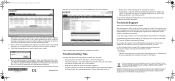
...in lower case letters and click Login. If disposed of your product at : http://support.netgear.com/app/answers/detail/a_id/11621/ For GNU General Public License (GPL) related information, please visit http://support.netgear.com/app/answers/detail/a_id/2649 WARNING!! Turn off the switch and computer. Registration...on the label of your product and use the telephone support service. Go to view the switch log in screen. 5. Click Web Browser Access to http://support.netgear.com for your equipment is in accordance with the laws of NETGEAR, Inc. This symbol was placed in the same ...
...in lower case letters and click Login. If disposed of your product at : http://support.netgear.com/app/answers/detail/a_id/11621/ For GNU General Public License (GPL) related information, please visit http://support.netgear.com/app/answers/detail/a_id/2649 WARNING!! Turn off the switch and computer. Registration...on the label of your product and use the telephone support service. Go to view the switch log in screen. 5. Click Web Browser Access to http://support.netgear.com for your equipment is in accordance with the laws of NETGEAR, Inc. This symbol was placed in the same ...
GS7xxTS-TPS Software Admin Manual
Page 2
... of NETGEAR, Inc. GS728TS, GS728TPS, GS752TS, and GS752TPS Gigabit Smart Switches ©2012 NETGEAR, Inc. All rights reserved. Revision History Publication Part Number 202-10995-01 Version v1.0 Publish Date February 2012 Comments First publication 2 Technical Support Thank you for more information about the topics covered in this manual, visit the Support website at http://support.netgear...
... of NETGEAR, Inc. GS728TS, GS728TPS, GS752TS, and GS752TPS Gigabit Smart Switches ©2012 NETGEAR, Inc. All rights reserved. Revision History Publication Part Number 202-10995-01 Version v1.0 Publish Date February 2012 Comments First publication 2 Technical Support Thank you for more information about the topics covered in this manual, visit the Support website at http://support.netgear...
GS7xxTS-TPS Software Admin Manual
Page 4
...118 Voice VLAN Properties 118 Voice VLAN Port Setting 119 Voice VLAN OUI 120 Auto-VoIP 121 4 GS728TS, GS728TPS, GS752TS, and GS752TPS Gigabit Smart Switches PoE/PoE+ (GS728TPS and GS752TPS Only 70 PoE Configuration 70 PoE Port Configuration 72 SNMP 75 SNMPv1/v2 75 Trap Configuration 77 Trap... Flags 78 SNMP Supported MIBs 79 SNMP v3 User Configuration 79 LLDP 80 LLDP Configuration 81 LLDP Port Settings 82...
...118 Voice VLAN Properties 118 Voice VLAN Port Setting 119 Voice VLAN OUI 120 Auto-VoIP 121 4 GS728TS, GS728TPS, GS752TS, and GS752TPS Gigabit Smart Switches PoE/PoE+ (GS728TPS and GS752TPS Only 70 PoE Configuration 70 PoE Port Configuration 72 SNMP 75 SNMPv1/v2 75 Trap Configuration 77 Trap... Flags 78 SNMP Supported MIBs 79 SNMP v3 User Configuration 79 LLDP 80 LLDP Configuration 81 LLDP Port Settings 82...

GS7xxTS-TPS Software Admin Manual
Page 7
GS728TS, GS728TPS, GS752TS, and GS752TPS Gigabit Smart Switches Switch Statistics 256 Port Statistics 259 Port Detailed Statistics 260 EAP Statistics 266 Cable Test 268 System Logs ...Configuration 289 Dual Image Status 291 Troubleshooting 292 Ping 292 Ping IPv6 293 Traceroute 294 Chapter 9 Accessing Help Online Help 296 Support 296 User Guide 297 Registration 298 Appendix A Hardware Specifications and Default Values Switch Specifications 300 GS728TS Specifications 300 GS728TPS Specifications 300 GS752TS Specifications 301 GS752TPS Specifications 301 Switch Performance 301 7
GS728TS, GS728TPS, GS752TS, and GS752TPS Gigabit Smart Switches Switch Statistics 256 Port Statistics 259 Port Detailed Statistics 260 EAP Statistics 266 Cable Test 268 System Logs ...Configuration 289 Dual Image Status 291 Troubleshooting 292 Ping 292 Ping IPv6 293 Traceroute 294 Chapter 9 Accessing Help Online Help 296 Support 296 User Guide 297 Registration 298 Appendix A Hardware Specifications and Default Values Switch Specifications 300 GS728TS Specifications 300 GS728TPS Specifications 300 GS752TS Specifications 301 GS752TPS Specifications 301 Switch Performance 301 7
GS7xxTS-TPS Software Admin Manual
Page 29
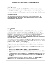
...To enable encryption, select the DES option in the public MIB, IF-MIB. GS728TS, GS728TPS, GS752TS, and GS752TPS switches use both standard public MIBs for authentication and encryption, the switch supports only one profile that page displays if you need to configure an SNMP manager to the.... For example, if the IP Addressing page is either MD5 or SHA. 3. Using SNMP The GS728TS, GS728TPS, GS752TS, and GS752TPS switches software supports the configuration of SNMP groups and users that support additional switch functionality. The main object for that can connect to configure. 29
...To enable encryption, select the DES option in the public MIB, IF-MIB. GS728TS, GS728TPS, GS752TS, and GS752TPS switches use both standard public MIBs for authentication and encryption, the switch supports only one profile that page displays if you need to configure an SNMP manager to the.... For example, if the IP Addressing page is either MD5 or SHA. 3. Using SNMP The GS728TS, GS728TPS, GS752TS, and GS752TPS switches software supports the configuration of SNMP groups and users that support additional switch functionality. The main object for that can connect to configure. 29

GS7xxTS-TPS Software Admin Manual
Page 30
..., 1/g2, 1/g3 3/g21, 3/g22 LAG interfaces are logical interfaces that are numbered sequentially starting from one. GS728TS, GS728TPS, GS752TS, and GS752TPS Gigabit Smart Switches Interface Naming Convention The GS728TS, GS728TPS, GS752TS, and GS752TPS switches software supports physical and logical interfaces. This interface is not configurable and is the internal switch interface responsible c1...
..., 1/g2, 1/g3 3/g21, 3/g22 LAG interfaces are logical interfaces that are numbered sequentially starting from one. GS728TS, GS728TPS, GS752TS, and GS752TPS Gigabit Smart Switches Interface Naming Convention The GS728TS, GS728TPS, GS752TS, and GS752TPS switches software supports physical and logical interfaces. This interface is not configurable and is the internal switch interface responsible c1...

