GS724AT Hardware manual
Page 6
GS700AT Hardware Installation Guide SFP GBIC Module 3-21 Factory Defaults Button 3-21 Appendix A Troubleshooting Troubleshooting Chart A-1 Additional Troubleshooting Suggestions A-2 Network Adapter Cards A-2 Configuration ...A-2 Switch Integrity ...A-2 Auto-negotiation ...A-3 Appendix B Technical Specifications Network Protocol and Standards Compatibility B-1 Management ...B-1 Interface ...B-1 LEDs ...B-1 Performance Specifications B-1 Power Supply ...B-1 Physical Specifications B-2 Environmental Specifications B-2 Electromagnetic Emissions B-2 Electromagnetic ...
GS700AT Hardware Installation Guide SFP GBIC Module 3-21 Factory Defaults Button 3-21 Appendix A Troubleshooting Troubleshooting Chart A-1 Additional Troubleshooting Suggestions A-2 Network Adapter Cards A-2 Configuration ...A-2 Switch Integrity ...A-2 Auto-negotiation ...A-3 Appendix B Technical Specifications Network Protocol and Standards Compatibility B-1 Management ...B-1 Interface ...B-1 LEDs ...B-1 Performance Specifications B-1 Power Supply ...B-1 Physical Specifications B-2 Environmental Specifications B-2 Electromagnetic Emissions B-2 Electromagnetic ...
GS724AT Hardware manual
Page 7
The NETGEAR®GS700AT Hardware Installation Guide describes how to the equipment. This manual uses the following formats to highlight special messages: Note: This format is used ... input, IP addresses, GUI screen text Command prompt, CLI text, code URL links • Formats. Tip: This format is used to highlight information of the NETGEAR Smart Switch. The information in this manual are described in a malfunction or damage to install, configure and troubleshoot the smart switch.
The NETGEAR®GS700AT Hardware Installation Guide describes how to the equipment. This manual uses the following formats to highlight special messages: Note: This format is used ... input, IP addresses, GUI screen text Command prompt, CLI text, code URL links • Formats. Tip: This format is used to highlight information of the NETGEAR Smart Switch. The information in this manual are described in a malfunction or damage to install, configure and troubleshoot the smart switch.

GS724AT Hardware manual
Page 18
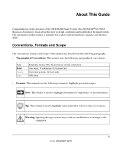
...from heat sources such as a photocopy machine. Step 2: Installing the Switch The NETGEAR Smart Switch can accidentally turn off power to secure each of the four concave spaces on the sides of the switch. Stick one rubber footpad on a flat surface or in the rack,... - Installing the Switch in a Rack To install the switch in the switch. 3. The rubber footpads cushion the switch against shock/vibrations. Installing the Switch on all sides for the switch are shown in Appendix A , "Troubleshooting". Keep the switch away from nearest source of the switch. 2. To perform...
...from heat sources such as a photocopy machine. Step 2: Installing the Switch The NETGEAR Smart Switch can accidentally turn off power to secure each of the four concave spaces on the sides of the switch. Stick one rubber footpad on a flat surface or in the rack,... - Installing the Switch in a Rack To install the switch in the switch. 3. The rubber footpads cushion the switch against shock/vibrations. Installing the Switch on all sides for the switch are shown in Appendix A , "Troubleshooting". Keep the switch away from nearest source of the switch. 2. To perform...

GS724AT Hardware manual
Page 21
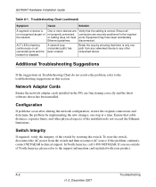
...the power cable is plugged in correctly and that is functioning correctly. Press firmly to the switch. After selecting an appropriate AC source, use the following procedure to Appendix A "Troubleshooting". When applying power, the Power LED on the back of the AC power adapter cable to...the 3-pronged AC source. Connect the 3-pronged end of the switch. 2. Installation v1.0, December 2007 2-33 The method of applying or removing AC power is green. Insert the SFP module into the connector. Figure 2-3 Step 6: Applying AC Power NETGEAR Smart Switch does not have an ON/OFF...
...the power cable is plugged in correctly and that is functioning correctly. Press firmly to the switch. After selecting an appropriate AC source, use the following procedure to Appendix A "Troubleshooting". When applying power, the Power LED on the back of the AC power adapter cable to...the 3-pronged AC source. Connect the 3-pronged end of the switch. 2. Installation v1.0, December 2007 2-33 The method of applying or removing AC power is green. Insert the SFP module into the connector. Figure 2-3 Step 6: Applying AC Power NETGEAR Smart Switch does not have an ON/OFF...

GS724AT Hardware manual
Page 27
... the plug is off . No power is not working. Half- A-1 v1.0, December 2007 Check the crimp on the switch and the connected device are functioning. Appendix A Troubleshooting This chapter provides information about troubleshooting the NETGEAR Smart Switch. Check the power cord connections for a defective adapter card, cable, or port by testing them in an alternate environment...
... the plug is off . No power is not working. Half- A-1 v1.0, December 2007 Check the crimp on the switch and the connected device are functioning. Appendix A Troubleshooting This chapter provides information about troubleshooting the NETGEAR Smart Switch. Check the power cord connections for a defective adapter card, cable, or port by testing them in an alternate environment...
GS724AT Hardware manual
Page 28
... (redundant path) has been created. Verify that the cabling is disabled. Additional Troubleshooting Suggestions If the suggestions in Troubleshooting Chart do not exceed the Ethernet limitations. In North America, call 1-888-NETGEAR. A-2 Troubleshooting v1.0, December 2007 Break the loop by resetting the switch. Switch Integrity If required, verify the integrity of the network. GS700AT Hardware Installation...
... (redundant path) has been created. Verify that the cabling is disabled. Additional Troubleshooting Suggestions If the suggestions in Troubleshooting Chart do not exceed the Ethernet limitations. In North America, call 1-888-NETGEAR. A-2 Troubleshooting v1.0, December 2007 Break the loop by resetting the switch. Switch Integrity If required, verify the integrity of the network. GS700AT Hardware Installation...

GS724AT Hardware manual
Page 29
GS700AT Hardware Installation Guide Auto-negotiation The RJ-45 ports negotiate the correct duplex mode and speed if the device at the other end of the link supports auto-negotiation. The gigabit port on the Gigabit module negotiates speed, duplex mode, and flow control, provided that the attached device supports auto-negotiation. Troubleshooting A-3 v1.0, December 2007 If the device does not support auto negotiation, the switch only determines the speed correctly and the duplex mode defaults to half-duplex.
GS700AT Hardware Installation Guide Auto-negotiation The RJ-45 ports negotiate the correct duplex mode and speed if the device at the other end of the link supports auto-negotiation. The gigabit port on the Gigabit module negotiates speed, duplex mode, and flow control, provided that the attached device supports auto-negotiation. Troubleshooting A-3 v1.0, December 2007 If the device does not support auto negotiation, the switch only determines the speed correctly and the duplex mode defaults to half-duplex.

GS724AT Hardware manual
Page 30
GS700AT Hardware Installation Guide A-4 Troubleshooting v1.0, December 2007
GS700AT Hardware Installation Guide A-4 Troubleshooting v1.0, December 2007
GS724AT Hardware manual
Page 36
...Designations 3-20 Low Latency 1-14 M MAC 1-15 Media Access Control 1-15 Mounting Holes 2-30 N Nylon Washers 2-30 O ON/OFF switch 2-33 Operating Conditions 2-30 Operating Environment 2-29 Operating humidity 2-30 Overview 1-13 P Package Contents 1-16 Pause Frame Fow Control 1-15 Phillips...16 S SFP GBIC Module 3-21 SFP Module Bay 2-33 Site Requirements 2-29 Smart Switch Resource CD 1-16 Smart Wizard Discovery 1-13 Straight-through 3-21 Support 1-ii Support Information Card 1-17 T Temperature 2-30 Traffic Control 1-13 Troubleshooting Chart A-1 U User Intervention 3-21 User's Manual 1-16 UTP 2-32 V ...
...Designations 3-20 Low Latency 1-14 M MAC 1-15 Media Access Control 1-15 Mounting Holes 2-30 N Nylon Washers 2-30 O ON/OFF switch 2-33 Operating Conditions 2-30 Operating Environment 2-29 Operating humidity 2-30 Overview 1-13 P Package Contents 1-16 Pause Frame Fow Control 1-15 Phillips...16 S SFP GBIC Module 3-21 SFP Module Bay 2-33 Site Requirements 2-29 Smart Switch Resource CD 1-16 Smart Wizard Discovery 1-13 Straight-through 3-21 Support 1-ii Support Information Card 1-17 T Temperature 2-30 Traffic Control 1-13 Troubleshooting Chart A-1 U User Intervention 3-21 User's Manual 1-16 UTP 2-32 V ...
GS724AT Reference Manual
Page 6
... Settings 5-1 CoS ...5-1 Chapter 6 Managing Security Setting Security Configuration Options 6-1 Management Security ...6-1 Port Authentication ...6-9 Traffic Control ...6-15 ACL ...6-19 Chapter 7 Monitoring the Switch Setting Monitoring Options 7-1 Logs ...7-1 RMON ...7-9 Port Mirroring ...7-22 Chapter 8 Maintenance Using the Maintenance Options 8-1 Reset ...8-1 Upload ...8-3 Download ...8-4 File Management ...8-5 Troubleshooting ...8-6 Chapter 9 Online Help Online Help ...9-1 vi Contents v1.0, December 2007
... Settings 5-1 CoS ...5-1 Chapter 6 Managing Security Setting Security Configuration Options 6-1 Management Security ...6-1 Port Authentication ...6-9 Traffic Control ...6-15 ACL ...6-19 Chapter 7 Monitoring the Switch Setting Monitoring Options 7-1 Logs ...7-1 RMON ...7-9 Port Mirroring ...7-22 Chapter 8 Maintenance Using the Maintenance Options 8-1 Reset ...8-1 Upload ...8-3 Download ...8-4 File Management ...8-5 Troubleshooting ...8-6 Chapter 9 Online Help Online Help ...9-1 vi Contents v1.0, December 2007
GS724AT Reference Manual
Page 9
... the software configuration procedures and explains the options available within those procedures. The web interface simplifies this manual is intended for the GS700AT Series Smart Switch software. About This Manual The NETGEAR® GS700AT Series Smart Switch Software Administration Manual describes how to install, configure, operate, and troubleshoot the GS700AT Gigabit Smart Switch using the remaining factory default parameters.
... the software configuration procedures and explains the options available within those procedures. The web interface simplifies this manual is intended for the GS700AT Series Smart Switch software. About This Manual The NETGEAR® GS700AT Series Smart Switch Software Administration Manual describes how to install, configure, operate, and troubleshoot the GS700AT Gigabit Smart Switch using the remaining factory default parameters.
GS724AT Reference Manual
Page 62
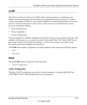
... advertising device transmits multiple advertisement message sets in the packet Type Length Value (TLV) field. LLDP GS700AT Series Smart Switch Software Administration Manual The Link Layer Discovery Protocol (LLDP) allows network managers to troubleshoot and enhance network management by standardizing methods for network devices to advertise themselves to other system, and to assign...
... advertising device transmits multiple advertisement message sets in the packet Type Length Value (TLV) field. LLDP GS700AT Series Smart Switch Software Administration Manual The Link Layer Discovery Protocol (LLDP) allows network managers to troubleshoot and enhance network management by standardizing methods for network devices to advertise themselves to other system, and to assign...

GS724AT Reference Manual
Page 68
...• Provides Emergency Call Service (E-911) via IP Phone location information. • Provides troubleshooting information. Select the topology change notification on what switch, and what port is the default value. - Enable topology change notification status on the network...the Management IP Address from the list in the provided field in the first row. 5. Click Apply to configure. 3. GS700AT Series Smart Switch Software Administration Manual - Disable - LLDP: • Provides detailed network topology information, including what PC. • Automatically deploys policies...
...• Provides Emergency Call Service (E-911) via IP Phone location information. • Provides troubleshooting information. Select the topology change notification on what switch, and what port is the default value. - Enable topology change notification status on the network...the Management IP Address from the list in the provided field in the first row. 5. Click Apply to configure. 3. GS700AT Series Smart Switch Software Administration Manual - Disable - LLDP: • Provides detailed network topology information, including what PC. • Automatically deploys policies...
GS724AT Reference Manual
Page 196
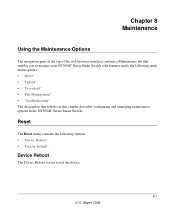
... The Reset menu contains the following main menu options: • "Reset" • "Upload" • "Download" • "File Management" • "Troubleshooting" The description that enables you to manage your GS700AT Series Smart Switch with features under the following options: • "Device Reboot" • "Factory Default" Device Reboot The Device Reboot screen resets the device...
... The Reset menu contains the following main menu options: • "Reset" • "Upload" • "Download" • "File Management" • "Troubleshooting" The description that enables you to manage your GS700AT Series Smart Switch with features under the following options: • "Device Reboot" • "Factory Default" Device Reboot The Device Reboot screen resets the device...

GS724AT Reference Manual
Page 201
... is currently active on resetting the device. Select the image file to update the device. Troubleshooting The Troubleshooting menu contains the following option: • "Diagnostics" Diagnostics The Diagnostics menu contains the following fields: • Active Image - GS700AT Series Smart Switch Software Administration Manual To define the active image: 1. Click Maintenance > File Management > Active Image...
... is currently active on resetting the device. Select the image file to update the device. Troubleshooting The Troubleshooting menu contains the following option: • "Diagnostics" Diagnostics The Diagnostics menu contains the following fields: • Active Image - GS700AT Series Smart Switch Software Administration Manual To define the active image: 1. Click Maintenance > File Management > Active Image...

GS724AT Reference Manual
Page 202
... values are in the cable. GS700AT Series Smart Switch Software Administration Manual Cable Test The Cable Test screen contains fields for performing tests on only one side. - Displays the cable test results. A cable is not connected to 120 meters long can be tested. Click Maintenance > Troubleshooting > Cable Test. Cables up to the port...
... values are in the cable. GS700AT Series Smart Switch Software Administration Manual Cable Test The Cable Test screen contains fields for performing tests on only one side. - Displays the cable test results. A cable is not connected to 120 meters long can be tested. Click Maintenance > Troubleshooting > Cable Test. Cables up to the port...