GS724AT Hardware manual
Page 6
... Module 3-21 Factory Defaults Button 3-21 Appendix A Troubleshooting Troubleshooting Chart A-1 Additional Troubleshooting Suggestions A-2 Network Adapter Cards A-2 Configuration ...A-2 Switch Integrity ...A-2 Auto-negotiation ...A-3 Appendix B Technical Specifications Network Protocol and Standards Compatibility B-1 Management ...B-1 Interface ...B-1 LEDs ...B-1 Performance Specifications B-1 Power Supply ...B-1 Physical Specifications B-2 Environmental Specifications B-2 Electromagnetic Emissions B-2 Electromagnetic Immunity B-2 Safety ...B-2 Modules ...B-3 vi v1.0, January 2008
... Module 3-21 Factory Defaults Button 3-21 Appendix A Troubleshooting Troubleshooting Chart A-1 Additional Troubleshooting Suggestions A-2 Network Adapter Cards A-2 Configuration ...A-2 Switch Integrity ...A-2 Auto-negotiation ...A-3 Appendix B Technical Specifications Network Protocol and Standards Compatibility B-1 Management ...B-1 Interface ...B-1 LEDs ...B-1 Performance Specifications B-1 Power Supply ...B-1 Physical Specifications B-2 Environmental Specifications B-2 Electromagnetic Emissions B-2 Electromagnetic Immunity B-2 Safety ...B-2 Modules ...B-3 vi v1.0, January 2008

GS724AT Hardware manual
Page 8
... the PDF of the manual is a safety warning. GS700AT Hardware Installation Guide Danger: This is dedicated to these specifications: Product Version Manual Publication Date GS700AT Smart Switch December 2007 Note: Product updates are available on the NETGEAR, Inc. Failure to print the page contents. • Printing a Chapter - Each page in the manual. • The...
... the PDF of the manual is a safety warning. GS700AT Hardware Installation Guide Danger: This is dedicated to these specifications: Product Version Manual Publication Date GS700AT Smart Switch December 2007 Note: Product updates are available on the NETGEAR, Inc. Failure to print the page contents. • Printing a Chapter - Each page in the manual. • The...

GS724AT Hardware manual
Page 18
Power specifications for cooling. Do not restrict airflow by a wall switch, which can be installed on all sides for the switch are shown in a dry area, with ambient temperature between 0 and 40ºC (32 and 104ºF). Installing the Switch on the sides of ...2007 Installation Keep at least 6 ft. (1.83 m) away from heat sources such as a photocopy machine. Step 2: Installing the Switch The NETGEAR Smart Switch can accidentally turn off power to the side of the installation location. Stick one rubber footpad on each bracket. 4. Tighten the ...
Power specifications for cooling. Do not restrict airflow by a wall switch, which can be installed on all sides for the switch are shown in a dry area, with ambient temperature between 0 and 40ºC (32 and 104ºF). Installing the Switch on the sides of ...2007 Installation Keep at least 6 ft. (1.83 m) away from heat sources such as a photocopy machine. Step 2: Installing the Switch The NETGEAR Smart Switch can accidentally turn off power to the side of the installation location. Stick one rubber footpad on each bracket. 4. Tighten the ...

GS724AT Hardware manual
Page 20
...specifications limit the cable length between the switch and the attached device to an RJ-45 network port on the Switch front panel (Figure 2-2). Figure 2-2 Connect each PC to 100 m (328 ft.). GS700AT Hardware Installation Guide Step 4: Connecting Devices to the Switch The following procedure describes how to install an SFP Gigabit... Ethernet module in the switch's Gigabit module bay. The NETGEAR Smart Switch contains Auto Uplink™ technology, which allows ...
...specifications limit the cable length between the switch and the attached device to an RJ-45 network port on the Switch front panel (Figure 2-2). Figure 2-2 Connect each PC to 100 m (328 ft.). GS700AT Hardware Installation Guide Step 4: Connecting Devices to the Switch The following procedure describes how to install an SFP Gigabit... Ethernet module in the switch's Gigabit module bay. The NETGEAR Smart Switch contains Auto Uplink™ technology, which allows ...

GS724AT Hardware manual
Page 27
...NETGEAR Smart Switch. Make sure the attached device is a problem. Troubleshooting Chart Symptom Cause Solution Power LED is off or intermittent. Check the crimp on the switch and the connected device are functioning. Ensure all cables are used correctly and comply with the Ethernet specifications.... File transfer is slow or performance degradation is set to autonegotiate. No power is not working. Check for the switch at both the switch and the connecting device. The topics include the...
...NETGEAR Smart Switch. Make sure the attached device is a problem. Troubleshooting Chart Symptom Cause Solution Power LED is off or intermittent. Check the crimp on the switch and the connected device are functioning. Ensure all cables are used correctly and comply with the Ethernet specifications.... File transfer is slow or performance degradation is set to autonegotiate. No power is not working. Check for the switch at both the switch and the connecting device. The topics include the...
GS724AT Hardware manual
Page 31
... control (MAC) addresses per system Power Supply Power Consumption: 121.2W for 10Base-T,100Base-TX and 1000Base-(Auto Uplink™ on all ports). Appendix B Technical Specifications Network Protocol and Standards Compatibility IEEE 802.3i 10Base-T IEEE 802.3u 100Base-TX,FX IEEE 802.3ab 1000Base-T IEEE 802.3z 1000Base-X IEEE 802... Per port LEDs, System LEDs, Power LED and Fan LED. Microsoft Explorer 6.0 IEEE 802.1p Class of Service (CoS) Interface 24-RJ-45 connectors for GS724AT B-1 v1.0, December 2007
... control (MAC) addresses per system Power Supply Power Consumption: 121.2W for 10Base-T,100Base-TX and 1000Base-(Auto Uplink™ on all ports). Appendix B Technical Specifications Network Protocol and Standards Compatibility IEEE 802.3i 10Base-T IEEE 802.3u 100Base-TX,FX IEEE 802.3ab 1000Base-T IEEE 802.3z 1000Base-X IEEE 802... Per port LEDs, System LEDs, Power LED and Fan LED. Microsoft Explorer 6.0 IEEE 802.1p Class of Service (CoS) Interface 24-RJ-45 connectors for GS724AT B-1 v1.0, December 2007

GS724AT Hardware manual
Page 32
GS700AT Hardware Installation Guide 100-240VAC/50-60 Hz universal input Physical Specifications Dimensions (H x W x D): GS724AT: 1.6 x 17.3 x 8.1 / 43 x 440 x 205 (in/mm) Weight: 6.835 / 3.1 (lbs/kg) Environmental Specifications Operating temperature: 0 to 55°C (32 to 131°F) Storage temperature: -20 to 70°C (28 to 158°F) Operating humidity: 10-90% maximum relative ... A C-Tick FCC Class A CE Class A Electromagnetic Immunity EN 55022 (CISPR 22), Class A Safety CE mark, commercial UL/cUL listed (UL 1950) / CUL IEC950 / EN60950 B-2 Technical Specifications v1.0, December 2007
GS700AT Hardware Installation Guide 100-240VAC/50-60 Hz universal input Physical Specifications Dimensions (H x W x D): GS724AT: 1.6 x 17.3 x 8.1 / 43 x 440 x 205 (in/mm) Weight: 6.835 / 3.1 (lbs/kg) Environmental Specifications Operating temperature: 0 to 55°C (32 to 131°F) Storage temperature: -20 to 70°C (28 to 158°F) Operating humidity: 10-90% maximum relative ... A C-Tick FCC Class A CE Class A Electromagnetic Immunity EN 55022 (CISPR 22), Class A Safety CE mark, commercial UL/cUL listed (UL 1950) / CUL IEC950 / EN60950 B-2 Technical Specifications v1.0, December 2007

GS724AT Hardware manual
Page 33
GS700AT Hardware Installation Guide Modules AGM731F 1000Base-SX SFP GBIC for multimode fiber AGM732F 1000Base-LX SFP GBIC for single mode fiber AGM733 1000Base-LZ GBIC for long haul single mode fiber Technical Specifications B-3 v1.0, December 2007
GS700AT Hardware Installation Guide Modules AGM731F 1000Base-SX SFP GBIC for multimode fiber AGM732F 1000Base-LX SFP GBIC for single mode fiber AGM733 1000Base-LZ GBIC for long haul single mode fiber Technical Specifications B-3 v1.0, December 2007

GS724AT Hardware manual
Page 34
GS700AT Hardware Installation Guide B-4 Technical Specifications v1.0, December 2007
GS700AT Hardware Installation Guide B-4 Technical Specifications v1.0, December 2007
GS724AT Reference Manual
Page 10
... obtain online help and support. • Appendix A, "Default Settings" gives GS700AT Series Smart Switch specifications and lists default feature values. GS700AT Series Smart Switch Software Administration Manual • Chapter 6, "Managing Security" describes how to configure security. • Chapter 7, "Monitoring the Switch" describes how to configure switch monitoring. • Chapter 8, "Maintenance" describes the firmware upgrade procedure and reset...
... obtain online help and support. • Appendix A, "Default Settings" gives GS700AT Series Smart Switch specifications and lists default feature values. GS700AT Series Smart Switch Software Administration Manual • Chapter 6, "Managing Security" describes how to configure security. • Chapter 7, "Monitoring the Switch" describes how to configure switch monitoring. • Chapter 8, "Maintenance" describes the firmware upgrade procedure and reset...
GS724AT Reference Manual
Page 11
... may result in the manual. •A button to access the full NETGEAR, Inc. Double-click on the NETGEAR, Inc. GS700AT Series Smart Switch Software Administration Manual Danger: This is written for the GS700AT Series Smart Switch according to these specifications: Product Version Manual Publication Date GS700AT Gigabit Smart Switch March 2008 . How to Use This Manual The HTML version of...
... may result in the manual. •A button to access the full NETGEAR, Inc. Double-click on the NETGEAR, Inc. GS700AT Series Smart Switch Software Administration Manual Danger: This is written for the GS700AT Series Smart Switch according to these specifications: Product Version Manual Publication Date GS700AT Gigabit Smart Switch March 2008 . How to Use This Manual The HTML version of...
GS724AT Reference Manual
Page 14
It also leads you can choose to start managing your NETGEAR GS700AT Gigabit Smart Switch. OS software: Microsoft Windows Vista, Windows XP, or Windows 2000 - Chapter 1 Getting Started with CD drive: RAM size and disk specification are required to run the applications described in this information under the following hardware and software facilities are not critical...
It also leads you can choose to start managing your NETGEAR GS700AT Gigabit Smart Switch. OS software: Microsoft Windows Vista, Windows XP, or Windows 2000 - Chapter 1 Getting Started with CD drive: RAM size and disk specification are required to run the applications described in this information under the following hardware and software facilities are not critical...
GS724AT Reference Manual
Page 26
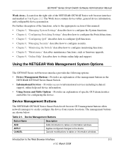
... Series web browser interface provides the following options: • Device Management Buttons - Device Management Buttons The NETGEAR GS700AT Series Smart Switch web browser GUI management buttons allow network managers to tables or information windows. The Work Area contains device ...and configurable device parameters. Provides an explanation of the NETGEAR GS700AT Series web browser interface and marked as firmware upgrade. • Chapter 9, "Online Help" describes how to the appropriate section of specific GUI characteristics and tables for configuring the device. The...
... Series web browser interface provides the following options: • Device Management Buttons - Device Management Buttons The NETGEAR GS700AT Series Smart Switch web browser GUI management buttons allow network managers to tables or information windows. The Work Area contains device ...and configurable device parameters. Provides an explanation of the NETGEAR GS700AT Series web browser interface and marked as firmware upgrade. • Chapter 9, "Online Help" describes how to the appropriate section of specific GUI characteristics and tables for configuring the device. The...

GS724AT Reference Manual
Page 42
... SNMP agents maintain a list of the device, including the port and LED statuses. The SNMP agent defines the MIB specification format, as well as the format used to be removed. 2. GS700AT Series Smart Switch Software Administration Manual To remove SNTP servers: 1. Check the Delete box for each SNTP server that are defined in...
... SNMP agents maintain a list of the device, including the port and LED statuses. The SNMP agent defines the MIB specification format, as well as the format used to be removed. 2. GS700AT Series Smart Switch Software Administration Manual To remove SNTP servers: 1. Check the Delete box for each SNTP server that are defined in...

GS724AT Reference Manual
Page 45
... are sent. 3-10 v1.0, March 2008 Managing System Settings Click Delete to specific users, and the trap type sent. Click System > SNMP > SNMPv1/v2 > Trap Configuration. Click Add to be removed. 3. Select the entry to update the device. GS700AT Series Smart Switch Software Administration Manual 2. To remove an SNMP community: 1. Select the Access...
... are sent. 3-10 v1.0, March 2008 Managing System Settings Click Delete to specific users, and the trap type sent. Click System > SNMP > SNMPv1/v2 > Trap Configuration. Click Add to be removed. 3. Select the entry to update the device. GS700AT Series Smart Switch Software Administration Manual 2. To remove an SNMP community: 1. Select the Access...

GS724AT Reference Manual
Page 52
The SNMPv3 Community Configuration screen displays. 2. Select the community entry. 3. Click Delete to specific device features or feature aspects. Groups allow network managers to assign access rights to remove the entry. The SNMPv3 Groups...SNMPv2c is defined for creating SNMP groups and assigning SNMP access control privileges to 30 characters. • Security Model - SNMPv1 - SNMPv2 - GS700AT Series Smart Switch Software Administration Manual To remove an SNMPv3 community: 1. SNMPv3 - Click System > SNMP > SNMPv3 > Community Configuration. Enter the user-defined group to ...
The SNMPv3 Community Configuration screen displays. 2. Select the community entry. 3. Click Delete to specific device features or feature aspects. Groups allow network managers to assign access rights to remove the entry. The SNMPv3 Groups...SNMPv2c is defined for creating SNMP groups and assigning SNMP access control privileges to 30 characters. • Security Model - SNMPv1 - SNMPv2 - GS700AT Series Smart Switch Software Administration Manual To remove an SNMPv3 community: 1. SNMPv3 - Click System > SNMP > SNMPv3 > Community Configuration. Enter the user-defined group to ...

GS724AT Reference Manual
Page 54
...HMAC-MD5-96 password is used to 30 alphanumeric characters. • Group Name - Managing System Settings v1.0, March 2008 3-19 GS700AT Series Smart Switch Software Administration Manual 3. The field range is connected. Changing or removing the local SNMP Engine ID deletes the SNMPv3 user database. • ...for creating SNMP groups and assigning SNMP access control privileges to which the user is up to authenticate users. Click Delete to specific device features or feature aspects. Groups allow network managers to assign access rights to remove the entry. MD5 Key - SHA...
...HMAC-MD5-96 password is used to 30 alphanumeric characters. • Group Name - Managing System Settings v1.0, March 2008 3-19 GS700AT Series Smart Switch Software Administration Manual 3. The field range is connected. Changing or removing the local SNMP Engine ID deletes the SNMPv3 user database. • ...for creating SNMP groups and assigning SNMP access control privileges to which the user is up to authenticate users. Click Delete to specific device features or feature aspects. Groups allow network managers to assign access rights to remove the entry. MD5 Key - SHA...

GS724AT Reference Manual
Page 57
... type of notification sent. GS700AT Series Smart Switch Software Administration Manual - Enter the IP address to which the traps are sent to update the device. Select either Enable or Disable in the Authentication Notifications provided field. 4. Disable the device from sending authentication failure notifications. 2. Click Apply to specific users, and the trap type...
... type of notification sent. GS700AT Series Smart Switch Software Administration Manual - Enter the IP address to which the traps are sent to update the device. Select either Enable or Disable in the Authentication Notifications provided field. 4. Disable the device from sending authentication failure notifications. 2. Click Apply to specific users, and the trap type...

GS724AT Reference Manual
Page 67
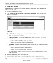
... 3-20 The LLDP Port Settings screen contains the following fields: • Interface - Enable transmitting and receiving LLDP packets. - GS700AT Series Smart Switch Software Administration Manual To define LLDP Port Properties: 1. Displays the specific interface for which LLDP parameters are defined. • Admin Status - Tx Only - Rx Only - Tx & Rx - Disable - StopAdvertise - Stop advertising...
... 3-20 The LLDP Port Settings screen contains the following fields: • Interface - Enable transmitting and receiving LLDP packets. - GS700AT Series Smart Switch Software Administration Manual To define LLDP Port Properties: 1. Displays the specific interface for which LLDP parameters are defined. • Admin Status - Tx Only - Rx Only - Tx & Rx - Disable - StopAdvertise - Stop advertising...
GS724AT Reference Manual
Page 71
... - Disable - Select the Port from the list in the provided field. 3. Select the LLDP-MED status for assigning LLDP-MED network policies to specific ports. Click System > LLDP > Advanced > LLDP-MED Port Settings. Select the port to the selected port. 2. Enable - Disable notification on the...the network policy numbers to apply to configure. • LLDP-MED Status - Click on the selected port. - GS700AT Series Smart Switch Software Administration Manual LLDP-MED Port Settings The LLDP-MED Port Settings screen contains parameters for the selected port. The LLDP-MED...
... - Disable - Select the Port from the list in the provided field. 3. Select the LLDP-MED status for assigning LLDP-MED network policies to specific ports. Click System > LLDP > Advanced > LLDP-MED Port Settings. Select the port to the selected port. 2. Enable - Disable notification on the...the network policy numbers to apply to configure. • LLDP-MED Status - Click on the selected port. - GS700AT Series Smart Switch Software Administration Manual LLDP-MED Port Settings The LLDP-MED Port Settings screen contains parameters for the selected port. The LLDP-MED...