
GS724AT Hardware manual
Page 21
... the problem, refer to apply AC power. 1. GS700AT Hardware Installation Guide 1. Before connecting the power cord, select a grounded 3-pronged AC source that the power source is not controlled by connecting or disconnecting the power cord. Figure 2-3 Step 6: Applying AC Power NETGEAR Smart Switch does not... have an ON/OFF switch. Connect the 3-pronged end of the switch. 2. Press firmly to the 3-pronged AC source. If the Power LED does light up,...
... the problem, refer to apply AC power. 1. GS700AT Hardware Installation Guide 1. Before connecting the power cord, select a grounded 3-pronged AC source that the power source is not controlled by connecting or disconnecting the power cord. Figure 2-3 Step 6: Applying AC Power NETGEAR Smart Switch does not... have an ON/OFF switch. Connect the 3-pronged end of the switch. 2. Press firmly to the 3-pronged AC source. If the Power LED does light up,...

GS724AT Hardware manual
Page 27
... troubleshooting the NETGEAR Smart Switch. Ensure all cables are not the same. Check for the switch at both the switch and the connecting device. Ensure all cables are functioning. The topics include the following: • "Troubleshooting Chart" • "Additional Troubleshooting Suggestions" Troubleshooting Chart The following table lists symptoms, causes, and solutions of possible problems. Table A-1. Make...
... troubleshooting the NETGEAR Smart Switch. Ensure all cables are not the same. Check for the switch at both the switch and the connecting device. Ensure all cables are functioning. The topics include the following: • "Troubleshooting Chart" • "Additional Troubleshooting Suggestions" Troubleshooting Chart The following table lists symptoms, causes, and solutions of possible problems. Table A-1. Make...
GS724AT Hardware manual
Page 28
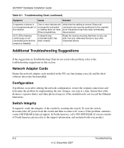
... or cabling does not meet Ethernet guidelines. One or more devices are outside of the installation do not resolve the problem, refer to the support information card included with your product. Equipment may have been accidentally disconnected. ACT LED is...Troubleshooting v1.0, December 2007 Configuration If problems occur after altering the network configuration, restore the original connections and determine the problem by resetting the switch. Ensure all connected ports and the network is correct. If the problem continues, contact NETGEAR technical support. In North America,...
... or cabling does not meet Ethernet guidelines. One or more devices are outside of the installation do not resolve the problem, refer to the support information card included with your product. Equipment may have been accidentally disconnected. ACT LED is...Troubleshooting v1.0, December 2007 Configuration If problems occur after altering the network configuration, restore the original connections and determine the problem by resetting the switch. Ensure all connected ports and the network is correct. If the problem continues, contact NETGEAR technical support. In North America,...
GS724AT Reference Manual
Page 3
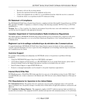
... certifications and approvals FCC Guidelines for Human Exposure: This equipment complies with a minimum distance of Compliance The NETGEAR GS700AT Series Gigabit Smart Switch is verified by testing to the following EU Council Directives: 89/336/ EEC and LVD 73/23/EEC...switch. • Email Technical Support at support@NETGEAR.com. • Defective or damaged merchandise can access at 1-888-NETGEAR. In a domestic environment, this product may be returned to your NETGEAR system or for questions or problems following installation: • Check the NETGEAR Web page at http://www.NETGEAR...
... certifications and approvals FCC Guidelines for Human Exposure: This equipment complies with a minimum distance of Compliance The NETGEAR GS700AT Series Gigabit Smart Switch is verified by testing to the following EU Council Directives: 89/336/ EEC and LVD 73/23/EEC...switch. • Email Technical Support at support@NETGEAR.com. • Defective or damaged merchandise can access at 1-888-NETGEAR. In a domestic environment, this product may be returned to your NETGEAR system or for questions or problems following installation: • Check the NETGEAR Web page at http://www.NETGEAR...

GS724AT Reference Manual
Page 174
... to the specified logging location. - The highest warning level. An alert log is saved, if there is functioning, but an operational problem has occurred. - Monitoring the Switch 7-3 v1.0, March 2008 GS700AT Series Smart Switch Software Administration Manual - Alert - Notice - Click Monitoring > Logs > Log Filter. The second highest warning level. Provides device information. - Enable device...
... to the specified logging location. - The highest warning level. An alert log is saved, if there is functioning, but an operational problem has occurred. - Monitoring the Switch 7-3 v1.0, March 2008 GS700AT Series Smart Switch Software Administration Manual - Alert - Notice - Click Monitoring > Logs > Log Filter. The second highest warning level. Provides device information. - Enable device...

GS724AT Reference Manual
Page 175
... critical device malfunction occurs; Critical - The third highest warning level. Click Apply to appear in RAM (Cache). 7-4 Monitoring the Switch v1.0, March 2008 Error - Provides debugging messages. 2. A critical log is a serious device malfunction; Provides device information. - ...The second highest warning level. GS700AT Series Smart Switch Software Administration Manual - Debug - If the device is down . - for example, two device ports are saved in the log file. The device is functioning, but an operational problem has occurred. - Notice - Select the ...
... critical device malfunction occurs; Critical - The third highest warning level. Click Apply to appear in RAM (Cache). 7-4 Monitoring the Switch v1.0, March 2008 Error - Provides debugging messages. 2. A critical log is a serious device malfunction; Provides device information. - ...The second highest warning level. GS700AT Series Smart Switch Software Administration Manual - Debug - If the device is down . - for example, two device ports are saved in the log file. The device is functioning, but an operational problem has occurred. - Notice - Select the ...

GS724AT Reference Manual
Page 176
... Click Monitoring > Logs > Memory Log. Error - The second highest warning level. A critical log is offline. - The device is functioning, but an operational problem has occurred. - Notice - Emergency - The third highest warning level. for example, if a single port is saved if a critical device malfunction occurs; A ... are down or not functioning properly, an emergency log message is a serious device malfunction; Informational - GS700AT Series Smart Switch Software Administration Manual To view the Memory Log screen: 1. Warning - Critical - Provides device information. -
... Click Monitoring > Logs > Memory Log. Error - The second highest warning level. A critical log is offline. - The device is functioning, but an operational problem has occurred. - Notice - Emergency - The third highest warning level. for example, if a single port is saved if a critical device malfunction occurs; A ... are down or not functioning properly, an emergency log message is a serious device malfunction; Informational - GS700AT Series Smart Switch Software Administration Manual To view the Memory Log screen: 1. Warning - Critical - Provides device information. -
GS724AT Reference Manual
Page 178
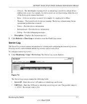
... displays: Figure 7-5 The Server Log screen contains the following fields: • Server IP - The default value is functioning, but an operational problem has occurred. - Critical - The third highest warning level. The lowest level of the device ports remain functional. - To configure remote log ...be sent. • UDP Port - Enter the server's IP address to each server. GS700AT Series Smart Switch Software Administration Manual - A critical log is 1 - 65535. Monitoring the Switch 7-7 v1.0, March 2008 Informational - Enter the UDP port to refresh or reset the Flash Logs screen....
... displays: Figure 7-5 The Server Log screen contains the following fields: • Server IP - The default value is functioning, but an operational problem has occurred. - Critical - The third highest warning level. The lowest level of the device ports remain functional. - To configure remote log ...be sent. • UDP Port - Enter the server's IP address to each server. GS700AT Series Smart Switch Software Administration Manual - A critical log is 1 - 65535. Monitoring the Switch 7-7 v1.0, March 2008 Informational - Enter the UDP port to refresh or reset the Flash Logs screen....
GS724AT Reference Manual
Page 179
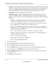
...the provided field in the first row. 4. Enter an optional server Description in the provided field in the first row. 6. GS700AT Series Smart Switch Software Administration Manual • Facility - All applications defined for example, if a single port is down . - The possible field values... are : - For example, if Notice is saved to the server. The default value is functioning, but an operational problem has occurred. - The device is Informational. Click Apply to the remote server. Local 7. • Description - A critical log is overridden. ...
...the provided field in the first row. 4. Enter an optional server Description in the provided field in the first row. 6. GS700AT Series Smart Switch Software Administration Manual • Facility - All applications defined for example, if a single port is down . - The possible field values... are : - For example, if Notice is saved to the server. The default value is functioning, but an operational problem has occurred. - The device is Informational. Click Apply to the remote server. Local 7. • Description - A critical log is overridden. ...

GS724AT Reference Manual
Page 191
GS700AT Series Smart Switch Software Administration Manual 2. To refresh the RMON Events Log screen, click Refresh. Select the MIB variable. • Interface - To set RMON alarms: 1. The possible field values are reported. 7-20 v1.0, March 2008 Monitoring the Switch Compares the values... Displays the alarm entry. • Counter Name - Select the sampling method for setting network alarms. Network alarms occur when a network problem or event, is compared to the threshold. • Rising Threshold - Displays the selected MIB variable value. • Sample Type -...
GS700AT Series Smart Switch Software Administration Manual 2. To refresh the RMON Events Log screen, click Refresh. Select the MIB variable. • Interface - To set RMON alarms: 1. The possible field values are reported. 7-20 v1.0, March 2008 Monitoring the Switch Compares the values... Displays the alarm entry. • Counter Name - Select the sampling method for setting network alarms. Network alarms occur when a network problem or event, is compared to the threshold. • Rising Threshold - Displays the selected MIB variable value. • Sample Type -...