Hardware Installation Guide
Page 2
... Part Number: Publication Version Number: GS716T and GS724T January 2011 GS716T/GS724T Series Smart Switch Smart Switch Business English 202-10510-02 1.0 ii v1.0, January 2011 Trademarks NETGEAR, the NETGEAR logo, and Auto Uplink are copyright Intoto, Inc. NETGEAR does not assume any liability that the Smart Switch has been suppressed in accordance with the conditions set out in the operating instructions. Portions of this document without...
... Part Number: Publication Version Number: GS716T and GS724T January 2011 GS716T/GS724T Series Smart Switch Smart Switch Business English 202-10510-02 1.0 ii v1.0, January 2011 Trademarks NETGEAR, the NETGEAR logo, and Auto Uplink are copyright Intoto, Inc. NETGEAR does not assume any liability that the Smart Switch has been suppressed in accordance with the conditions set out in the operating instructions. Portions of this document without...

Hardware Installation Guide
Page 4
GS716T/GS724T Hardware Installation Guide Step 3: Checking the Installation 4-15 Step 4: Connecting Devices to the Switch 4-16 Step 5: Installing an SFP GBIC Module 4-16 Step 6: Applying AC Power 4-17 Step 7: Managing the Switch using a Web Browser or the PC Utility 4-18 Appendix A Troubleshooting Troubleshooting Chart A-19 Additional Troubleshooting Suggestions A-20 Network Adapter Cards A-20 Configuration ...A-20 Switch Integrity ...A-20 Auto-Negotiation A-21 Appendix B Technical Specifications Index iv v1.0, January 2011
GS716T/GS724T Hardware Installation Guide Step 3: Checking the Installation 4-15 Step 4: Connecting Devices to the Switch 4-16 Step 5: Installing an SFP GBIC Module 4-16 Step 6: Applying AC Power 4-17 Step 7: Managing the Switch using a Web Browser or the PC Utility 4-18 Appendix A Troubleshooting Troubleshooting Chart A-19 Additional Troubleshooting Suggestions A-20 Network Adapter Cards A-20 Configuration ...A-20 Switch Integrity ...A-20 Auto-Negotiation A-21 Appendix B Technical Specifications Index iv v1.0, January 2011
Hardware Installation Guide
Page 5
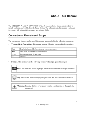
... this manual is used to highlight a procedure that will save time or resources. The information in a malfunction or damage to install, configure and troubleshoot the Smart Switch. About This Manual The NETGEAR® ProSafeTM GS716T/GS724T Hardware Installation Guide describes how to the equipment. This manual uses the following paragraphs: • Typographical Conventions. Tip: This format is intended for readers with intermediate computer and Internet skills...
... this manual is used to highlight a procedure that will save time or resources. The information in a malfunction or damage to install, configure and troubleshoot the Smart Switch. About This Manual The NETGEAR® ProSafeTM GS716T/GS724T Hardware Installation Guide describes how to the equipment. This manual uses the following paragraphs: • Typographical Conventions. Tip: This format is intended for readers with intermediate computer and Internet skills...
Hardware Installation Guide
Page 7
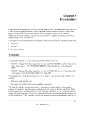
... port and switch information, VLAN for traffic control, port trunking for the observation, configuration, and control of 10/100/1000 Mbps and two Form-factor slots, which support 1000 (1000BASE-SX/LX)/100 Mbps SFP. This chapter serves as an introduction to the Smart Switch and provides the following NETGEAR Smart Switches: • GS716T - Using Gigabit ports, high-speed connections can be made to a server or network backbone. For example: • Linking to high-speed servers...
... port and switch information, VLAN for traffic control, port trunking for the observation, configuration, and control of 10/100/1000 Mbps and two Form-factor slots, which support 1000 (1000BASE-SX/LX)/100 Mbps SFP. This chapter serves as an introduction to the Smart Switch and provides the following NETGEAR Smart Switches: • GS716T - Using Gigabit ports, high-speed connections can be made to a server or network backbone. For example: • Linking to high-speed servers...
Hardware Installation Guide
Page 8
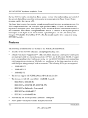
... the highest speed. GS716T/GS724T Hardware Installation Guide Service (CoS) for fiber connections using SFP GBIC modules. The following list identifies the key features of the network. These features provide better understanding and control of the NETGEAR Smart Switch. • 16/24 RJ-45 10/100/1000 Mbps auto sensing Giga switching ports. • 2 Small Form-factor Pluggable (SFP) GBIC slots which function as combo ports. All ports can be free-standing, or rack mounted in...
... the highest speed. GS716T/GS724T Hardware Installation Guide Service (CoS) for fiber connections using SFP GBIC modules. The following list identifies the key features of the network. These features provide better understanding and control of the NETGEAR Smart Switch. • 16/24 RJ-45 10/100/1000 Mbps auto sensing Giga switching ports. • 2 Small Form-factor Pluggable (SFP) GBIC slots which function as combo ports. All ports can be free-standing, or rack mounted in...
Hardware Installation Guide
Page 9
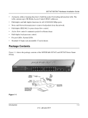
.../1000 Mbps ports. • Store-and-Forward transmission to remove bad packets from the network. • Full-duplex IEEE 802.3x pause frame flow control. • Active flow control to build the packet-forwarding information table. Figure 1-1 Introduction 1-3 v1.0, January 2011 Package Contents Figure 1-1 shows the package contents of the NETGEAR GS716T and GS724T Series Smart Switch. GS716T/GS724T Hardware Installation Guide • Automatic address learning function...
.../1000 Mbps ports. • Store-and-Forward transmission to remove bad packets from the network. • Full-duplex IEEE 802.3x pause frame flow control. • Active flow control to build the packet-forwarding information table. Figure 1-1 Introduction 1-3 v1.0, January 2011 Package Contents Figure 1-1 shows the package contents of the NETGEAR GS716T and GS724T Series Smart Switch. GS716T/GS724T Hardware Installation Guide • Automatic address learning function...
Hardware Installation Guide
Page 11
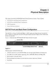
... link partner automatically Figure 2-1 illustrates the NETGEAR GS716T Smart Switch front panel: System LEDs Figure 2-1 10/100/1000 Mbps Ethernet Ports SFP Ports The front panel contains the following: • 16 RJ-45 connectors for 10/100/1000 Mbps auto sensing Gigabit Ethernet switching ports. • Two SFP slots for SFP modules supporting 1000 (1000BASE-SX/LX)/100 Mbps SFP. • Reset button to restart the device. • Recessed default reset button to restore the device back to the factory defaults...
... link partner automatically Figure 2-1 illustrates the NETGEAR GS716T Smart Switch front panel: System LEDs Figure 2-1 10/100/1000 Mbps Ethernet Ports SFP Ports The front panel contains the following: • 16 RJ-45 connectors for 10/100/1000 Mbps auto sensing Gigabit Ethernet switching ports. • Two SFP slots for SFP modules supporting 1000 (1000BASE-SX/LX)/100 Mbps SFP. • Reset button to restart the device. • Recessed default reset button to restore the device back to the factory defaults...
Hardware Installation Guide
Page 12
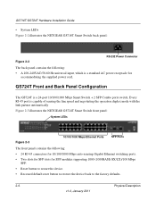
.../100/1000 Mbps auto-sensing Gigabit Ethernet switching ports. • Two slots for SFP slots for accommodating the supplied power cord. Every RJ-45 port is a standard AC power receptacle for SFP modules supporting 1000 (1000BASE-SX/LX)/100 Mbps SFP. • Reset button to restart the device. • Recessed default reset button to restore the device back to the factory defaults. 2-6 Physical Description v1.0, January 2011 GS724T Front and Back Panel Configuration The GS724T is...
.../100/1000 Mbps auto-sensing Gigabit Ethernet switching ports. • Two slots for SFP slots for accommodating the supplied power cord. Every RJ-45 port is a standard AC power receptacle for SFP modules supporting 1000 (1000BASE-SX/LX)/100 Mbps SFP. • Reset button to restart the device. • Recessed default reset button to restore the device back to the factory defaults. 2-6 Physical Description v1.0, January 2011 GS724T Front and Back Panel Configuration The GS724T is...
Hardware Installation Guide
Page 14
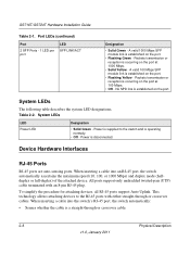
... port. • Flashing Green - All ports support only unshielded twisted-pair (UTP) cable terminated with either straight-through or crossover cable. 2-8 Physical Description v1.0, January 2011 A valid 1000 Mbps SFP module link is disconnected. Packets transmission or reception is operating normally. • Off - System LEDs The following table describes the system LED designations. Power is supplied to the RJ-45 ports with an 8-pin RJ-45 plug. Device Hardware Interfaces...
... port. • Flashing Green - All ports support only unshielded twisted-pair (UTP) cable terminated with either straight-through or crossover cable. 2-8 Physical Description v1.0, January 2011 A valid 1000 Mbps SFP module link is disconnected. Packets transmission or reception is operating normally. • Off - System LEDs The following table describes the system LED designations. Power is supplied to the RJ-45 ports with an 8-pin RJ-45 plug. Device Hardware Interfaces...
Hardware Installation Guide
Page 15
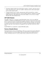
... the link to the attached device requires a "normal" connection (such as when connecting the port to a PC) or an "uplink" connection (such as the AGM731F, AGM732F, or AGM733 from NETGEAR, allowing fiber connections on the network. The SFP GBIC bay accommodates a standard SFP GBIC module. Factory Defaults Button The Smart Switch has a Factory Default button so that you enable the Factory Default button, all settings, including the password, VLAN settings and port configurations will be used at any given time. For example, both...
... the link to the attached device requires a "normal" connection (such as when connecting the port to a PC) or an "uplink" connection (such as the AGM731F, AGM732F, or AGM733 from NETGEAR, allowing fiber connections on the network. The SFP GBIC bay accommodates a standard SFP GBIC module. Factory Defaults Button The Smart Switch has a Factory Default button so that you enable the Factory Default button, all settings, including the password, VLAN settings and port configurations will be used at any given time. For example, both...

Hardware Installation Guide
Page 18
The rack-mount kit supplied with the switch is grounded and physically secure. Provide a flat table or shelf surface. • Rack-mount installations - Locate the switch in the following steps: Step 1: Preparing the Site Step 2: Installing the Switch Step 3: Checking the Installation Step 4: Connecting Devices to the front panel RJ-45 ports, view the front panel LEDs, and access power connector. Site Requirements Characteristics Requirements Mounting Access • Desktop installations - Table 4-1. v1.0, January 2011 4-13 Use a 17-inch (48.3-centimeter...
The rack-mount kit supplied with the switch is grounded and physically secure. Provide a flat table or shelf surface. • Rack-mount installations - Locate the switch in the following steps: Step 1: Preparing the Site Step 2: Installing the Switch Step 3: Checking the Installation Step 4: Connecting Devices to the front panel RJ-45 ports, view the front panel LEDs, and access power connector. Site Requirements Characteristics Requirements Mounting Access • Desktop installations - Table 4-1. v1.0, January 2011 4-13 Use a 17-inch (48.3-centimeter...

Hardware Installation Guide
Page 21
... ft.). Note: Ethernet specifications limit the cable length between the switch and the attached device to make these connections. If an SFP GBIC module is not being installed at this time, skip this procedure. To install an SFP GBIC module: 4-16 v1.0, January 2011 Installation GS716T/GS724T Hardware Installation Guide Step 4: Connecting Devices to the Switch The following procedure describes how to install an SFP Gigabit Ethernet module in the switch's Gigabit module bay. Step 5: Installing an SFP GBIC Module The following...
... ft.). Note: Ethernet specifications limit the cable length between the switch and the attached device to make these connections. If an SFP GBIC module is not being installed at this time, skip this procedure. To install an SFP GBIC module: 4-16 v1.0, January 2011 Installation GS716T/GS724T Hardware Installation Guide Step 4: Connecting Devices to the Switch The following procedure describes how to install an SFP Gigabit Ethernet module in the switch's Gigabit module bay. Step 5: Installing an SFP GBIC Module The following...
Hardware Installation Guide
Page 22
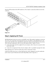
... of applying or removing AC power is Green. Installation v1.0, January 2011 4-17 Connect the female end of the supplied AC power adapter cable to the switch. Press firmly to apply AC power. 1. Connect the 3-pronged end of the AC power adapter cable to Appendix A . After selecting an appropriate outlet, use the following procedure to ensure the module seats into the SFP module bay. GS716T/GS724T Hardware Installation Guide Insert the SFP module into the...
... of applying or removing AC power is Green. Installation v1.0, January 2011 4-17 Connect the female end of the supplied AC power adapter cable to the switch. Press firmly to apply AC power. 1. Connect the 3-pronged end of the AC power adapter cable to Appendix A . After selecting an appropriate outlet, use the following procedure to ensure the module seats into the SFP module bay. GS716T/GS724T Hardware Installation Guide Insert the SFP module into the...
Hardware Installation Guide
Page 23
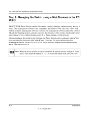
... managing the switch, see the GS716T/GS724T Series Software Administration Manual on the device. The default IP address is not required for the switch to work. However, the management software enables the setup of VLAN and Trunking features, and also improves the efficiency of the switch, which results in the improvement of its overall performance as well as the performance of the network. After powering up , there is a default IP address already configured...
... managing the switch, see the GS716T/GS724T Series Software Administration Manual on the device. The default IP address is not required for the switch to work. However, the management software enables the setup of VLAN and Trunking features, and also improves the efficiency of the switch, which results in the improvement of its overall performance as well as the performance of the network. After powering up , there is a default IP address already configured...

Hardware Installation Guide
Page 24
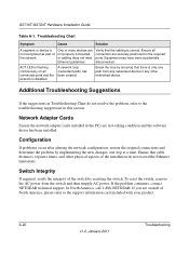
... intermittent. Check the power cord connections for a defective adapter card, cable, or port by testing them in an alternate environment where all products are correct and comply with Ethernet specifications. File transfer is slow or performance degradation is not working. Ensure all cables used are functioning. Troubleshooting v1.0, January 2011 A-19 Topics include the following: • Troubleshooting Chart • Additional Troubleshooting Suggestions Troubleshooting Chart The following table lists symptoms, causes...
... intermittent. Check the power cord connections for a defective adapter card, cable, or port by testing them in an alternate environment where all products are correct and comply with Ethernet specifications. File transfer is slow or performance degradation is not working. Ensure all cables used are functioning. Troubleshooting v1.0, January 2011 A-19 Topics include the following: • Troubleshooting Chart • Additional Troubleshooting Suggestions Troubleshooting Chart The following table lists symptoms, causes...
Hardware Installation Guide
Page 25
... problem, refer to the support information card included with your product. In North America, call 1-888-NETGEAR. A network loop (redundant path) has been created. Ensure that cable distances, repeater limits, and other networked device. To reset the switch, remove the AC power from any networked device to any other physical aspects of the switch by implementing the new changes, one path from the switch and then reapply AC power. GS716T/GS724T Hardware Installation Guide Table A-1. Troubleshooting...
... problem, refer to the support information card included with your product. In North America, call 1-888-NETGEAR. A network loop (redundant path) has been created. Ensure that cable distances, repeater limits, and other networked device. To reset the switch, remove the AC power from any networked device to any other physical aspects of the switch by implementing the new changes, one path from the switch and then reapply AC power. GS716T/GS724T Hardware Installation Guide Table A-1. Troubleshooting...

Hardware Installation Guide
Page 27
...-T (Auto Uplink™ on all ports). 2 Small Form-factor Pluggable (SFP) slots for SFP module. Appendix B Technical Specifications Network Protocol and Standards Compatibility IEEE 802.3i 10BASE-T IEEE 802.3u 100BASE-TX,FX IEEE 802.3ab 1000BASE-T IEEE 802.3z 1000BASE-X IEEE 802.3x flow control Management Windows 2000 + XP, Vista; LEDs Per port (Gigabit): Link/Activity, Speed Per device: Power Technical Specifications v1.0, January 2011 B-23 Disabled by default. Microsoft...
...-T (Auto Uplink™ on all ports). 2 Small Form-factor Pluggable (SFP) slots for SFP module. Appendix B Technical Specifications Network Protocol and Standards Compatibility IEEE 802.3i 10BASE-T IEEE 802.3u 100BASE-TX,FX IEEE 802.3ab 1000BASE-T IEEE 802.3z 1000BASE-X IEEE 802.3x flow control Management Windows 2000 + XP, Vista; LEDs Per port (Gigabit): Link/Activity, Speed Per device: Power Technical Specifications v1.0, January 2011 B-23 Disabled by default. Microsoft...

Hardware Installation Guide
Page 28
GS716T/GS724T Hardware Installation Guide Performance Specifications Forwarding modes: Store-and-forward Bandwidth: 32 Gbps (for GS716T); 48 Gbps (for GS724T) Address database size: 8K media access control (MAC) addresses per system Mean Time Between Failure (MTBF): 307,681 hours for GS716T; 282,516 hours for GS724T Power Supply Power Consumption: 16.5W for GS716T, 21.5W for GS724T 100-240VAC/50-60 Hz universal input Physical Specifications Dimensions (H x W x D): 1.7 x 17.3 x 10.2 / 43 x 440...
GS716T/GS724T Hardware Installation Guide Performance Specifications Forwarding modes: Store-and-forward Bandwidth: 32 Gbps (for GS716T); 48 Gbps (for GS724T) Address database size: 8K media access control (MAC) addresses per system Mean Time Between Failure (MTBF): 307,681 hours for GS716T; 282,516 hours for GS724T Power Supply Power Consumption: 16.5W for GS716T, 21.5W for GS724T 100-240VAC/50-60 Hz universal input Physical Specifications Dimensions (H x W x D): 1.7 x 17.3 x 10.2 / 43 x 440...

Hardware Installation Guide
Page 30
... Auto Sensing 1-2 Auto Uplink 2-8, 2-9 Auto-negotiating 1-2 Auto-sensing 2-8 B Back-pressure 1-3 Brackets 4-14 C Category 5 Unshielded Twisted-Pair 1-2 Checking the Installation 4-15 Class of Service 1-1 Combo Port 2-9 Combo Ports 1-2 Connecting Devices to the Switch 4-16 Copper 1-1 Crossover 2-8 D Default IP Address 4-18 Default Reset Button 2-5, 2-6 Device Hardware Interfaces 2-8 Duplex Mode 2-8 E Example of Desktop Switching 3-11 F Factory Default Button 2-9 Factory Defaults 2-5 Fiber Connectivity 1-1 Flat Surface 4-14 Full-duplex 1-2 G GBIC 1-2, 2-9 Gigabit Ports 1-1 H High-speed Servers...
... Auto Sensing 1-2 Auto Uplink 2-8, 2-9 Auto-negotiating 1-2 Auto-sensing 2-8 B Back-pressure 1-3 Brackets 4-14 C Category 5 Unshielded Twisted-Pair 1-2 Checking the Installation 4-15 Class of Service 1-1 Combo Port 2-9 Combo Ports 1-2 Connecting Devices to the Switch 4-16 Copper 1-1 Crossover 2-8 D Default IP Address 4-18 Default Reset Button 2-5, 2-6 Device Hardware Interfaces 2-8 Duplex Mode 2-8 E Example of Desktop Switching 3-11 F Factory Default Button 2-9 Factory Defaults 2-5 Fiber Connectivity 1-1 Flat Surface 4-14 Full-duplex 1-2 G GBIC 1-2, 2-9 Gigabit Ports 1-1 H High-speed Servers...

Hardware Installation Guide
Page 31
... 1-3 Phillips Screwdriver 4-14 Index-28 Port LEDs 2-7 Power cord 1-4 Preparing the Site 4-13 R Rack 4-14 Rack-mount Kit 1-4, 4-14 Reset Button 2-5, 2-6 RJ-45 1-2 RJ-45 Ports 2-8 Rubber footpads 1-4, 4-14 S SFP GBIC Module 2-9 SFP LINK/ACT LED 2-8 SFP Module Bay 4-17 Site Requirements 4-13 Small Form-factor Pluggable (SFP) 1-2 Smart Switch Resource CD 1-4 Smart Control Center 1-2 Straight-through 2-8 Support Information Card 1-4 System LEDs 2-8 T Temperature 4-14 Traffic Control 1-1 Troubleshooting Chart A-19 U User Intervention 2-9 User's Manual 1-4 UTP 4-16 V Ventilation 4-14 v1.0, January...
... 1-3 Phillips Screwdriver 4-14 Index-28 Port LEDs 2-7 Power cord 1-4 Preparing the Site 4-13 R Rack 4-14 Rack-mount Kit 1-4, 4-14 Reset Button 2-5, 2-6 RJ-45 1-2 RJ-45 Ports 2-8 Rubber footpads 1-4, 4-14 S SFP GBIC Module 2-9 SFP LINK/ACT LED 2-8 SFP Module Bay 4-17 Site Requirements 4-13 Small Form-factor Pluggable (SFP) 1-2 Smart Switch Resource CD 1-4 Smart Control Center 1-2 Straight-through 2-8 Support Information Card 1-4 System LEDs 2-8 T Temperature 4-14 Traffic Control 1-1 Troubleshooting Chart A-19 U User Intervention 2-9 User's Manual 1-4 UTP 4-16 V Ventilation 4-14 v1.0, January...


