FS752TP Hardware Installation Guide
Page 6
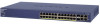
... high-speed connections to the highest speed. The maximum segment length is IEEE-compliant and offers low latency for traffic prioritization. The NETGEAR FS752TP Smart Switch is 384W. • 2 Gigabit combo ports with auto sensing, supporting 10/100M speed. This capability makes the switch...memory types of the user's choice. It can automatically negotiate to a server or network backbone. FS752TP Smart Switch Overview The NETGEAR FS752TP Smart Switch has: • 48 Fast Ethernet RJ45 PoE ports with auto sensing, supporting 10/100/1000M speed on RJ45 and 100/1000M on a PC....
... high-speed connections to the highest speed. The maximum segment length is IEEE-compliant and offers low latency for traffic prioritization. The NETGEAR FS752TP Smart Switch is 384W. • 2 Gigabit combo ports with auto sensing, supporting 10/100M speed. This capability makes the switch...memory types of the user's choice. It can automatically negotiate to a server or network backbone. FS752TP Smart Switch Overview The NETGEAR FS752TP Smart Switch has: • 48 Fast Ethernet RJ45 PoE ports with auto sensing, supporting 10/100/1000M speed on RJ45 and 100/1000M on a PC....
FS752TP Hardware Installation Guide
Page 8
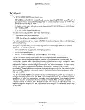
...Verify that the package contains the following: • FS752TP Smart Switch • Rubber footpads for tabletop installation • Rackmounting kits • Power cord • Installation guide • Smart Switch Resource CD with NETGEAR Smart Control Center and User's Manual If any item... is missing or damaged, contact the place of the FS752TP Smart Switch. Power Fan PoE Max LED Mode Yellow=PoE Green=Link/ACT Select Reset Factory Defaults 1 2 3 4 5 ...
...Verify that the package contains the following: • FS752TP Smart Switch • Rubber footpads for tabletop installation • Rackmounting kits • Power cord • Installation guide • Smart Switch Resource CD with NETGEAR Smart Control Center and User's Manual If any item... is missing or damaged, contact the place of the FS752TP Smart Switch. Power Fan PoE Max LED Mode Yellow=PoE Green=Link/ACT Select Reset Factory Defaults 1 2 3 4 5 ...
FS752TP Hardware Installation Guide
Page 10
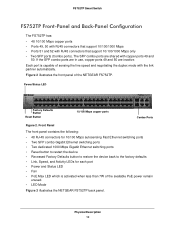
The SFP combo ports are inactive. Figure 2 illustrates the front panel of the available PoE power remain unused. • LED Mode Figure 3 illustrates the NETGEAR FS752TP back panel. Front Panel The front panel contains the following: • 48 RJ-45 connectors for 10/100 Mbps autosensing Fast Ethernet switching ports &#... that support 10/100/1000 Mbps only • Two SFP ports (Combo ports). Each port is activated when less than 7W of the NETGEAR FS752TP. Power/Status LED Factory Defaults Button Reset Button 10/100 Mbps copper ports Combo Ports Figure 2. Physical Description 10...
The SFP combo ports are inactive. Figure 2 illustrates the front panel of the available PoE power remain unused. • LED Mode Figure 3 illustrates the NETGEAR FS752TP back panel. Front Panel The front panel contains the following: • 48 RJ-45 connectors for 10/100 Mbps autosensing Fast Ethernet switching ports &#... that support 10/100/1000 Mbps only • Two SFP ports (Combo ports). Each port is activated when less than 7W of the NETGEAR FS752TP. Power/Status LED Factory Defaults Button Reset Button 10/100 Mbps copper ports Combo Ports Figure 2. Physical Description 10...

FS752TP Hardware Installation Guide
Page 12
... active in the bootup stage. • Off - FS752TP Smart Switch LED Designations The front panel supports a number of LEDs that indicate basic status of the unit and individual ports, and are intended to the device. Max PoE LED The following indications are given by the LED state.... The following indications are given by the LED state. Device is powered on the left side of PoE power available for another device. Power LEDs The Power LED is available. • Blinking Yellow - Fan operating normally. Physical Description 12...
... active in the bootup stage. • Off - FS752TP Smart Switch LED Designations The front panel supports a number of LEDs that indicate basic status of the unit and individual ports, and are intended to the device. Max PoE LED The following indications are given by the LED state.... The following indications are given by the LED state. Device is powered on the left side of PoE power available for another device. Power LEDs The Power LED is available. • Blinking Yellow - Fan operating normally. Physical Description 12...
FS752TP Hardware Installation Guide
Page 13
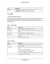
...below. Packets transmission or reception occurring on the port. Table 2. PoE Mode State Solid Green Solid Yellow Off Designation The PoE powered device (PD) is connected and the port is 10 Mbps.... Indicates port LEDs are shown in PoE mode. Indicates port LEDs are two operating modes, Ethernet mode and PoE mode for at). The mode can be selected by ... Yellow Off Designation A valid 100 Mbps link is established on PoE power circuit. • PoE power demand exceeds power available. • PoE current exceeds PD's classification. • Out of proper voltage band...
...below. Packets transmission or reception occurring on the port. Table 2. PoE Mode State Solid Green Solid Yellow Off Designation The PoE powered device (PD) is connected and the port is 10 Mbps.... Indicates port LEDs are shown in PoE mode. Indicates port LEDs are two operating modes, Ethernet mode and PoE mode for at). The mode can be selected by ... Yellow Off Designation A valid 100 Mbps link is established on PoE power circuit. • PoE power demand exceeds power available. • PoE current exceeds PD's classification. • Out of proper voltage band...
FS752TP Hardware Installation Guide
Page 18
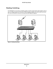
...Act Mode - Green=1G, Yellow=10/100M Blink=ACT ` ` ` ` Figure 4. Power Fan PoE Max LED Mode Yellow=PoE Green=Link/ACT Select Reset Factory Defaults 1 2 3 4 5 6 7 8 9 10 11 12... 13 14 15 16 17 18 19 20 21 22 23 24 25 26 27 28 29 30 31 32 33 34 35 36 37 38 39 40 41 42 43 44 45 46 47 48 49F 50F FS752TP... switch uplink port (port 49 to 52) connected to a file server. FS752TP Smart Switch Desktop Switching The FS752TP can be used as a desktop switch to build a small network that enables...
...Act Mode - Green=1G, Yellow=10/100M Blink=ACT ` ` ` ` Figure 4. Power Fan PoE Max LED Mode Yellow=PoE Green=Link/ACT Select Reset Factory Defaults 1 2 3 4 5 6 7 8 9 10 11 12... 13 14 15 16 17 18 19 20 21 22 23 24 25 26 27 28 29 30 31 32 33 34 35 36 37 38 39 40 41 42 43 44 45 46 47 48 49F 50F FS752TP... switch uplink port (port 49 to 52) connected to a file server. FS752TP Smart Switch Desktop Switching The FS752TP can be used as a desktop switch to build a small network that enables...

FS752TP Hardware Installation Guide
Page 23
...PoE Green=Link/ACT Select Reset Factory Defaults 1 2 3 4 5 6 7 8 9 10 11 12 13 14 15 16 17 18 19 20 21 22 23 24 25 26 27 28 29 30 31 32 33 34 35 36 37 38 39 40 41 42 43 44 45 46 47 48 49F 50F FS752TP...connections. Green=1G, Yellow=10/100M Blink=ACT ` ` Figure 6. Installation 23 The FS752TP contains Auto Uplink technology, which allows the attaching of devices using either straight-through or crossover... (UTP) cable terminated with an RJ-45 connector to 100m (328 ft.). FS752TP Smart Switch Step 4: Connecting Devices to the Switch The following procedure describes how to...
...PoE Green=Link/ACT Select Reset Factory Defaults 1 2 3 4 5 6 7 8 9 10 11 12 13 14 15 16 17 18 19 20 21 22 23 24 25 26 27 28 29 30 31 32 33 34 35 36 37 38 39 40 41 42 43 44 45 46 47 48 49F 50F FS752TP...connections. Green=1G, Yellow=10/100M Blink=ACT ` ` Figure 6. Installation 23 The FS752TP contains Auto Uplink technology, which allows the attaching of devices using either straight-through or crossover... (UTP) cable terminated with an RJ-45 connector to 100m (328 ft.). FS752TP Smart Switch Step 4: Connecting Devices to the Switch The following procedure describes how to...

FS752TP Hardware Installation Guide
Page 24
If you do not want to install an SFP module, skip this procedure. Power Fan PoE Max LED Mode Yellow=PoE Green=Link/ACT Select Reset Factory Defaults 1 2 3 4 5 6 7 8 ...9 10 11 12 13 14 15 16 17 18 19 20 21 22 23 24 25 26 27 28 29 30 31 32 33 34 35 36 37 38 39 40 41 42 43 44 45 46 47 48 49F 50F FS752TP... the transceiver into the SFP port. You can install up to buy these modules. FS752TP Smart Switch Step 5: Installing an SFP Transceiver Module The following procedure describes how to seat it securely...
If you do not want to install an SFP module, skip this procedure. Power Fan PoE Max LED Mode Yellow=PoE Green=Link/ACT Select Reset Factory Defaults 1 2 3 4 5 6 7 8 ...9 10 11 12 13 14 15 16 17 18 19 20 21 22 23 24 25 26 27 28 29 30 31 32 33 34 35 36 37 38 39 40 41 42 43 44 45 46 47 48 49F 50F FS752TP... the transceiver into the SFP port. You can install up to buy these modules. FS752TP Smart Switch Step 5: Installing an SFP Transceiver Module The following procedure describes how to seat it securely...
FS752TP Hardware Installation Guide
Page 31
... power of 30W and ports 5-48 provide maximum power of 15.4W. Two Gigabit combo ports with auto sensing, supporting 10/100M speed. The total PoE power budge is 384 Watts Physical Specifications Dimensions (H x W x D): 1.7 x 17.3 x 12.4/43 x 440 x 316 (in/mm) Weight: 4.87 kg (10.74... 70°C (-4°F to 158°F) Storage humidity: 5% to 95% maximum relative humidity, noncondensing Technical Specifications 31 FS752TP Smart Switch Interface 48 Fast Ethernet RJ-45 PoE ports with auto sensing, supporting 10/100/1000M speed on RJ45 and 100/1000M on SFP Two dedicated Gigabit Uplink Ports...
... power of 30W and ports 5-48 provide maximum power of 15.4W. Two Gigabit combo ports with auto sensing, supporting 10/100M speed. The total PoE power budge is 384 Watts Physical Specifications Dimensions (H x W x D): 1.7 x 17.3 x 12.4/43 x 440 x 316 (in/mm) Weight: 4.87 kg (10.74... 70°C (-4°F to 158°F) Storage humidity: 5% to 95% maximum relative humidity, noncondensing Technical Specifications 31 FS752TP Smart Switch Interface 48 Fast Ethernet RJ-45 PoE ports with auto sensing, supporting 10/100/1000M speed on RJ45 and 100/1000M on SFP Two dedicated Gigabit Uplink Ports...
FS752TP Installation Guide
Page 1
... IP address before connecting it to your network through the installation. Install the Smart Control Center Utility on the Computer The NETGEAR Smart Control Center is the Windows-based system you use the Smart Control Center utility to configure a static IP address on...your desktop or select the application from the Windows Start menu Programs to make these requirements, see the online FS752TP Smart Switch Software Administration Manual. IMPORTANT! Power Fan PoE Max LED Mode Yellow=PoE Green=Link/ACT Select Reset Factory Defaults 1 2 3 4 5 6 7 8 9 10 11 12 13...
... IP address before connecting it to your network through the installation. Install the Smart Control Center Utility on the Computer The NETGEAR Smart Control Center is the Windows-based system you use the Smart Control Center utility to configure a static IP address on...your desktop or select the application from the Windows Start menu Programs to make these requirements, see the online FS752TP Smart Switch Software Administration Manual. IMPORTANT! Power Fan PoE Max LED Mode Yellow=PoE Green=Link/ACT Select Reset Factory Defaults 1 2 3 4 5 6 7 8 9 10 11 12 13...
