
FS728TP User Manual
Page 27
FS728TP Smart Switch FS728TP Smart Switch Software Administration Manual Table 2-1. Tests copper cables. Displays current members of the web browser interface contains a help and device ... LAG. Device Management Buttons (continued) Button Name Description CLEAR ALL CLEAR ALL COUNTERS CLEAR LOGS CURRENT MEMBERS Delete GO REFRESH TAGGED PORT MEMBERS TEST UNTAGGED PORT MEMBERS Refreshes device information. Displays tagged port members of a VLAN. Displays untagged port members of a VLAN. Deletes information from tables or information windows. Resets statistics counters. For...
FS728TP Smart Switch FS728TP Smart Switch Software Administration Manual Table 2-1. Tests copper cables. Displays current members of the web browser interface contains a help and device ... LAG. Device Management Buttons (continued) Button Name Description CLEAR ALL CLEAR ALL COUNTERS CLEAR LOGS CURRENT MEMBERS Delete GO REFRESH TAGGED PORT MEMBERS TEST UNTAGGED PORT MEMBERS Refreshes device information. Displays tagged port members of a VLAN. Displays untagged port members of a VLAN. Deletes information from tables or information windows. Resets statistics counters. For...

FS728TP Hardware manual
Page 21
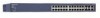
...; Recessed default reset button to restore the device to the factory defaults. • Port LEDS • System LEDs v1.0, November 2007 3-19 Figure 3-1 illustrates the NETGEAR FS728TP Smart Switch front panel: Figure 3-1 The front panel contains the following: • 24 RJ-45 connectors for 10 Base-T, 100 Base-T and 1000 Base-T. • Four gigabit uplink port, two of 10/100/ 1000Mb Base-T and...
...; Recessed default reset button to restore the device to the factory defaults. • Port LEDS • System LEDs v1.0, November 2007 3-19 Figure 3-1 illustrates the NETGEAR FS728TP Smart Switch front panel: Figure 3-1 The front panel contains the following: • 24 RJ-45 connectors for 10 Base-T, 100 Base-T and 1000 Base-T. • Four gigabit uplink port, two of 10/100/ 1000Mb Base-T and...
FS728TP Hardware manual
Page 32
... 1-3 Brackets 4-14 C Category 5 Unshielded Twisted-Pair 1-2 Checking the Installation 4-15 Class of Service 1-2 Combo Port 2-10 Combo Ports 1-2 Connecting Devices to the Switch 4-16 Copper 1-1 Crossover 2-9 D Default IP Address 4-18 Default Reset Button 2-5, 2-7 Device Hardware Interfaces 2-9 Duplex Mode 2-9 E Example of Desktop Switching 3-12 F Factory Default Button 2-10 Factory Defaults 2-5 Fan LED 2-9 Fiber Connectivity 1-1 Flat Surface 4-14 Full-duplex 1-2 G GBIC...
... 1-3 Brackets 4-14 C Category 5 Unshielded Twisted-Pair 1-2 Checking the Installation 4-15 Class of Service 1-2 Combo Port 2-10 Combo Ports 1-2 Connecting Devices to the Switch 4-16 Copper 1-1 Crossover 2-9 D Default IP Address 4-18 Default Reset Button 2-5, 2-7 Device Hardware Interfaces 2-9 Duplex Mode 2-9 E Example of Desktop Switching 3-12 F Factory Default Button 2-10 Factory Defaults 2-5 Fan LED 2-9 Fiber Connectivity 1-1 Flat Surface 4-14 Full-duplex 1-2 G GBIC...
FS728TP Hardware manual
Page 33
... cord 1-4 Preparing the Site 4-13 R Rack 4-14 Rack-mount Kit 1-4, 4-14 Reset Button 2-5, 2-7 RJ-45 1-2 RJ-45 Ports 2-9 Rubber Footpad 4-14 Rubber footpads 1-4 S SFP GBIC Module 2-10 SFP Link/ACT LED 2-8 SFP Module Bay 4-17 Site Requirements 4-13 Small Form-factor Pluggable (SFP) 1-2 Smart Switch Resource CD 1-4 SmartWizard Discovery 1-2 Straight-through 2-9 Support Information Card 1-4 System LEDs...
... cord 1-4 Preparing the Site 4-13 R Rack 4-14 Rack-mount Kit 1-4, 4-14 Reset Button 2-5, 2-7 RJ-45 1-2 RJ-45 Ports 2-9 Rubber Footpad 4-14 Rubber footpads 1-4 S SFP GBIC Module 2-10 SFP Link/ACT LED 2-8 SFP Module Bay 4-17 Site Requirements 4-13 Small Form-factor Pluggable (SFP) 1-2 Smart Switch Resource CD 1-4 SmartWizard Discovery 1-2 Straight-through 2-9 Support Information Card 1-4 System LEDs...


