
FS728TP User Manual
Page 9
FS728TP Smart Switch FS728TP Smart Switch Software Administration Manual Flash Log ...7-6 Server Log ...7-7 RMON ...7-9 Basic ...7-9 Advanced ...7-11 Port Mirroring ...7-22 Port Mirroring ...7-23 Chapter 8 Maintenance Using the Maintenance Options 8-1 Reset ...8-1 Device Reboot ...8-1 Factory Default ...8-2 Upload ...8-3 Upload ...8-3 Download ...8-4 Download ...8-4 File Management ...8-5 Active Image ...8-5 Troubleshooting ...8-6 Diagnostics ...8-6 Chapter 9 Online Help Online Help ...9-1 Support ...9-1 User Guide ...9-2 Appendix A Default Settings Index ix Contents v1.0, December 2007
FS728TP Smart Switch FS728TP Smart Switch Software Administration Manual Flash Log ...7-6 Server Log ...7-7 RMON ...7-9 Basic ...7-9 Advanced ...7-11 Port Mirroring ...7-22 Port Mirroring ...7-23 Chapter 8 Maintenance Using the Maintenance Options 8-1 Reset ...8-1 Device Reboot ...8-1 Factory Default ...8-2 Upload ...8-3 Upload ...8-3 Download ...8-4 Download ...8-4 File Management ...8-5 Active Image ...8-5 Troubleshooting ...8-6 Diagnostics ...8-6 Chapter 9 Online Help Online Help ...9-1 Support ...9-1 User Guide ...9-2 Appendix A Default Settings Index ix Contents v1.0, December 2007
FS728TP User Manual
Page 10
... Chapter 4, "Configuring Switching Settings" describes how to configure the Switching functions. • ...FS728TP Smart Switch in this configuration at all of Ethernet and networking concepts. How to Use This Book This document describes configuration commands for the FS728TP Smart Switch software. x v1.0, December 2007 About This Manual The NETGEAR® FS728TP Smart Switch FS728TP Smart Switch Software Administration Manual describes how to install, configure, operate, and troubleshoot the FS728TP 10/100 PoE Smart Switch with Gigabit Ports using the remaining factory default...
... Chapter 4, "Configuring Switching Settings" describes how to configure the Switching functions. • ...FS728TP Smart Switch in this configuration at all of Ethernet and networking concepts. How to Use This Book This document describes configuration commands for the FS728TP Smart Switch software. x v1.0, December 2007 About This Manual The NETGEAR® FS728TP Smart Switch FS728TP Smart Switch Software Administration Manual describes how to install, configure, operate, and troubleshoot the FS728TP 10/100 PoE Smart Switch with Gigabit Ports using the remaining factory default...

FS728TP User Manual
Page 25
...FS728TP Smart Switch FS728TP Smart Switch Software Administration Manual 2. Each feature expands to the Web Browser Interface v1.0, December 2007 Located on the top of the different features that can be configured as part of the NETGEAR FS728TP web browser interface and marked as 1 in Figure 2-2. Enter the password (the factory default... is password) and click Login. The home screen of the FS728TP Smart Switch browser interface displays.
...FS728TP Smart Switch FS728TP Smart Switch Software Administration Manual 2. Each feature expands to the Web Browser Interface v1.0, December 2007 Located on the top of the different features that can be configured as part of the NETGEAR FS728TP web browser interface and marked as 1 in Figure 2-2. Enter the password (the factory default... is password) and click Login. The home screen of the FS728TP Smart Switch browser interface displays.

FS728TP User Manual
Page 115
... in the interface entry row. 5-4 Configuring QoS v1.0, December 2007 FS728TP Smart Switch FS728TP Smart Switch Software Administration Manual To configure CoS interface parameters: 1. Checked - Select the default CoS value for incoming packets for which a VLAN priority (VPT) is not defined. • Restore Defaults - Restore the factory CoS default settings to the ports. - Select the interface. 3. Check or uncheck the Restore...
... in the interface entry row. 5-4 Configuring QoS v1.0, December 2007 FS728TP Smart Switch FS728TP Smart Switch Software Administration Manual To configure CoS interface parameters: 1. Checked - Select the default CoS value for incoming packets for which a VLAN priority (VPT) is not defined. • Restore Defaults - Restore the factory CoS default settings to the ports. - Select the interface. 3. Check or uncheck the Restore...

FS728TP User Manual
Page 119
FS728TP Smart Switch FS728TP Smart Switch Software Administration Manual To map CoS values to Queue Mapping • CoS - The CoS to Queue Mapping screen displays: Figure 5-5 The CoS to Queue Mapping ... values are supported (Lowest, Low, Normal and High). Check or uncheck the Restore Defaults box in the provided fields. 3. Restore the factory default settings for mapping CoS values to a forwarding queue. - Four traffic priority queues are : - Restore the device factory defaults for mapping CoS values to a forwarding queue. Displays the CoS priority tag values, where...
FS728TP Smart Switch FS728TP Smart Switch Software Administration Manual To map CoS values to Queue Mapping • CoS - The CoS to Queue Mapping screen displays: Figure 5-5 The CoS to Queue Mapping ... values are supported (Lowest, Low, Normal and High). Check or uncheck the Restore Defaults box in the provided fields. 3. Restore the factory default settings for mapping CoS values to a forwarding queue. - Four traffic priority queues are : - Restore the device factory defaults for mapping CoS values to a forwarding queue. Displays the CoS priority tag values, where...

FS728TP User Manual
Page 121
Check or uncheck the Restore Defaults box in the provided fields. 3. FS728TP Smart Switch FS728TP Smart Switch Software Administration Manual • Restore Defaults- Restore the factory default settings for each DSCP In value in the provided field. 4. The possible field values are: - Unchecked - Checked - Maintain the current DSCP mapping settings. 2. Select the Queue values for DSCP mapping values. - Restore the DSCP Mapping device factory default values. Click Apply to update the device. 5-10 v1.0, December 2007 Configuring QoS
Check or uncheck the Restore Defaults box in the provided fields. 3. FS728TP Smart Switch FS728TP Smart Switch Software Administration Manual • Restore Defaults- Restore the factory default settings for each DSCP In value in the provided field. 4. The possible field values are: - Unchecked - Checked - Maintain the current DSCP mapping settings. 2. Select the Queue values for DSCP mapping values. - Restore the DSCP Mapping device factory default values. Click Apply to update the device. 5-10 v1.0, December 2007 Configuring QoS

FS728TP User Manual
Page 172
... The navigation pane at the top of the web browser interface contains a Maintenance tab that enables you to manage your FS728TP Smart Switch with features under the following options: • "Device Reboot" • "Factory Default" Device Reboot The Device Reboot screen resets the device. 8-1 v1.0, December 2007 Reset The Reset menu contains the following main...
... The navigation pane at the top of the web browser interface contains a Maintenance tab that enables you to manage your FS728TP Smart Switch with features under the following options: • "Device Reboot" • "Factory Default" Device Reboot The Device Reboot screen resets the device. 8-1 v1.0, December 2007 Reset The Reset menu contains the following main...

FS728TP User Manual
Page 173
... following field: 8-2 v1.0, December 2007 Maintenance Confirm the rebooting operation. 3. Restoring factory defaults results in erasing the configuration file.To reset the device to reset the device. The Factory Default screen displays: Figure 8-2 The Factory Default screen contains the following field: 2. Click Apply to the factory defaults: 1. FS728TP Smart Switch FS728TP Smart Switch Software Administration Manual To reset the device: 1. Check the confirmation box...
... following field: 8-2 v1.0, December 2007 Maintenance Confirm the rebooting operation. 3. Restoring factory defaults results in erasing the configuration file.To reset the device to reset the device. The Factory Default screen displays: Figure 8-2 The Factory Default screen contains the following field: 2. Click Apply to the factory defaults: 1. FS728TP Smart Switch FS728TP Smart Switch Software Administration Manual To reset the device: 1. Check the confirmation box...

FS728TP User Manual
Page 174
... Server IP Address to the factory defaults. Upload The Upload menu contains the following fields: • File Type - Firmware - Click Maintenance > Upload. To back up using the Upload screen. Click Apply to reset the device to which the Firmware or Configuration file is uploaded. • Remote Filename - FS728TP Smart Switch FS728TP Smart Switch Software Administration Manual • Note...
... Server IP Address to the factory defaults. Upload The Upload menu contains the following fields: • File Type - Firmware - Click Maintenance > Upload. To back up using the Upload screen. Click Apply to reset the device to which the Firmware or Configuration file is uploaded. • Remote Filename - FS728TP Smart Switch FS728TP Smart Switch Software Administration Manual • Note...
FS728TP User Manual
Page 182
...) Auto-negotiation Auto-negotiation Disabled Disabled DHCP enabled password 802.1q based VLAN Disabled Optimized for the NETGEAR Model FS728TP Smart Switch. Table A-1. You can always configure the switch to default settings by using the Factory Reset function from a Web browser. Appendix A Default Settings This appendix provides default settings for flow control, all ports set normal priority A-1 v1.0, December 2007
...) Auto-negotiation Auto-negotiation Disabled Disabled DHCP enabled password 802.1q based VLAN Disabled Optimized for the NETGEAR Model FS728TP Smart Switch. Table A-1. You can always configure the switch to default settings by using the Factory Reset function from a Web browser. Appendix A Default Settings This appendix provides default settings for flow control, all ports set normal priority A-1 v1.0, December 2007
FS728TP Hardware manual
Page 6
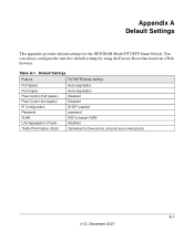
Device Hardware Interfaces 3-22 RJ-45 Ports ...3-22 SFP GBIC Module 3-23 Factory Defaults Button 3-23 Appendix A Troubleshooting Troubleshooting Chart A-1 Additional Troubleshooting Suggestions A-2 Network Adapter Cards A-2 Configuration ...A-2 Switch Integrity ...A-2 Auto-negotiation ...A-3 Appendix B Technical Specifications Network Protocol and Standards Compatibility B-1 Management ...B-1 Interface ...B-1 LEDs ...B-1 Performance Specifications B-2 Power Supply ...B-2 Physical Specifications B-2 Environmental Specifications B-2 Electromagnetic Emissions B-2 Electromagnetic ...
Device Hardware Interfaces 3-22 RJ-45 Ports ...3-22 SFP GBIC Module 3-23 Factory Defaults Button 3-23 Appendix A Troubleshooting Troubleshooting Chart A-1 Additional Troubleshooting Suggestions A-2 Network Adapter Cards A-2 Configuration ...A-2 Switch Integrity ...A-2 Auto-negotiation ...A-3 Appendix B Technical Specifications Network Protocol and Standards Compatibility B-1 Management ...B-1 Interface ...B-1 LEDs ...B-1 Performance Specifications B-2 Power Supply ...B-2 Physical Specifications B-2 Environmental Specifications B-2 Electromagnetic Emissions B-2 Electromagnetic ...

FS728TP Hardware manual
Page 21
... 10/100/ 1000Mb Base-T and 2GbE combo (Copper/Fiber) ports. Figure 3-1 illustrates the NETGEAR FS728TP Smart Switch front panel: Figure 3-1 The front panel contains the following: • 24 RJ-45 connectors for SFP modules supporting 1000(1000Base-SX/LX)/100M SFP. • Reset button to restart the device. • Recessed default reset button to restore the device to the factory defaults...
... 10/100/ 1000Mb Base-T and 2GbE combo (Copper/Fiber) ports. Figure 3-1 illustrates the NETGEAR FS728TP Smart Switch front panel: Figure 3-1 The front panel contains the following: • 24 RJ-45 connectors for SFP modules supporting 1000(1000Base-SX/LX)/100M SFP. • Reset button to restart the device. • Recessed default reset button to restore the device to the factory defaults...
FS728TP Hardware manual
Page 24
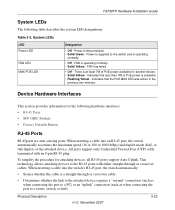
FS728TP Hardware Installation Guide System LEDs The following hardware interfaces: • RJ-45 Ports • SFP GBIC Module • Factory Defaults Button RJ-45 Ports RJ-45ports are auto-sensing ports. Table 3-2. Power is supplied to the RJ-45 ports with an 8-pin RJ-45 plug. There is ... is operating normally. • Solid Yellow - This technology allows attaching devices to the switch and is available. • Flashing Yellow - When inserting a cable into an RJ-45 port, the switch automatically ascertains the maximum speed (10 or 100 or 1000 Mbps) and duplex mode (half-
FS728TP Hardware Installation Guide System LEDs The following hardware interfaces: • RJ-45 Ports • SFP GBIC Module • Factory Defaults Button RJ-45 Ports RJ-45ports are auto-sensing ports. Table 3-2. Power is supplied to the RJ-45 ports with an 8-pin RJ-45 plug. There is ... is operating normally. • Solid Yellow - This technology allows attaching devices to the switch and is available. • Flashing Yellow - When inserting a cable into an RJ-45 port, the switch automatically ascertains the maximum speed (10 or 100 or 1000 Mbps) and duplex mode (half-
FS728TP Hardware manual
Page 25
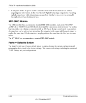
... standard SFP GBIC modules, such as the AGM731F, AGM732F, or AGM733 from NETGEAR, allowing fiber connections on the network. Factory Defaults Button The Smart Switch has a Factory default button to enable clearing the current configuration and returning the device back to use...port, sharing a connection with the attached device, without requiring user intervention. In this way, the Auto Uplink technology compensates for setting uplink connections, while eliminating concern about whether to the factory settings. FS728TP Hardware Installation Guide • Configures the RJ-45 port...
... standard SFP GBIC modules, such as the AGM731F, AGM732F, or AGM733 from NETGEAR, allowing fiber connections on the network. Factory Defaults Button The Smart Switch has a Factory default button to enable clearing the current configuration and returning the device back to use...port, sharing a connection with the attached device, without requiring user intervention. In this way, the Auto Uplink technology compensates for setting uplink connections, while eliminating concern about whether to the factory settings. FS728TP Hardware Installation Guide • Configures the RJ-45 port...
FS728TP Hardware manual
Page 32
...-Pair 1-2 Checking the Installation 4-15 Class of Service 1-2 Combo Port 2-10 Combo Ports 1-2 Connecting Devices to the Switch 4-16 Copper 1-1 Crossover 2-9 D Default IP Address 4-18 Default Reset Button 2-5, 2-7 Device Hardware Interfaces 2-9 Duplex Mode 2-9 E Example of Desktop Switching 3-12 F Factory Default Button 2-10 Factory Defaults 2-5 Fan LED 2-9 Fiber Connectivity 1-1 Flat Surface 4-14 Full-duplex 1-2 G GBIC 1-2, 2-10 Gigabit Ports 1-1 H High-speed Servers 1-1 v1.0, November 2007 Index-1
...-Pair 1-2 Checking the Installation 4-15 Class of Service 1-2 Combo Port 2-10 Combo Ports 1-2 Connecting Devices to the Switch 4-16 Copper 1-1 Crossover 2-9 D Default IP Address 4-18 Default Reset Button 2-5, 2-7 Device Hardware Interfaces 2-9 Duplex Mode 2-9 E Example of Desktop Switching 3-12 F Factory Default Button 2-10 Factory Defaults 2-5 Fan LED 2-9 Fiber Connectivity 1-1 Flat Surface 4-14 Full-duplex 1-2 G GBIC 1-2, 2-10 Gigabit Ports 1-1 H High-speed Servers 1-1 v1.0, November 2007 Index-1


