AGM731F Product specification
Page 2
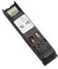
...pluggable 3.3V Small-Form-Factor transceiver module designed expressly for IEEE 802.3z/Gigabit Ethernet Compliant with the 1.0625GBd Fiber Channel FC-PI 100-M5-SN-I Rev.13 Compliant with Industry Standard RFT Electrical Connector and Cage Single + 3.3V Power Supply ... Applications This transceiver is compatible with the Gigabit Ethernet standards, as well as the SFP Multisource Agreement (MSA). Gigabit Ethernet Fibre channel Switch to Switch interface Switched backplane applications File server interface Performance Data Link up to 550m in 50/125µm Multi Mode Fiber Data Link up to...
...pluggable 3.3V Small-Form-Factor transceiver module designed expressly for IEEE 802.3z/Gigabit Ethernet Compliant with the 1.0625GBd Fiber Channel FC-PI 100-M5-SN-I Rev.13 Compliant with Industry Standard RFT Electrical Connector and Cage Single + 3.3V Power Supply ... Applications This transceiver is compatible with the Gigabit Ethernet standards, as well as the SFP Multisource Agreement (MSA). Gigabit Ethernet Fibre channel Switch to Switch interface Switched backplane applications File server interface Performance Data Link up to 550m in 50/125µm Multi Mode Fiber Data Link up to...
AGM731F Product specification
Page 4
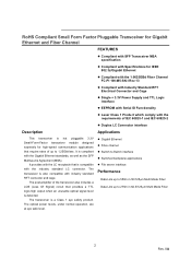
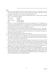
...: 1. These are 20%~80% values 2. Typ. Max. The sensitivity is provided at a BER of 1×10⁻¹⁰ or better with the IEEE 802.3z/D2 specification, and is class 1 laser eye safety Sensitivity (Avg.) Input Optical Wavelength PIN -17 dBm 2 λ 850 nm LOS-
...: 1. These are 20%~80% values 2. Typ. Max. The sensitivity is provided at a BER of 1×10⁻¹⁰ or better with the IEEE 802.3z/D2 specification, and is class 1 laser eye safety Sensitivity (Avg.) Input Optical Wavelength PIN -17 dBm 2 λ 850 nm LOS-
AGM731F Product specification
Page 5
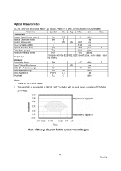
...SFP Transceiver Electrical Pad Layout Pin Function Definitions Pin Num. 1 2 Name VeeT TX Fault Function Transmitter Ground Transmitter Fault Indication Plug Seq. 1 3 3 TX Disable Transmitter Disable 3 4 MOD-DEF2 Module Definition 2 3 5 MOD-DEF1 Module Definition 1 3 6 MOD-DEF0 Module Definition 0 3 7 Rate Select Not Connect...TD+ Transmit Data In 3 19 TD- Inv. Notes Note 1 Note 2 Module disables on high or open Note 3, 2 wire serial ID interface Note 3, 2 wire serial ID interface Note 3, Grounded in Module Function not available Note 4 Note 5 Note 5 Note 5 Note 6 Note...
...SFP Transceiver Electrical Pad Layout Pin Function Definitions Pin Num. 1 2 Name VeeT TX Fault Function Transmitter Ground Transmitter Fault Indication Plug Seq. 1 3 3 TX Disable Transmitter Disable 3 4 MOD-DEF2 Module Definition 2 3 5 MOD-DEF1 Module Definition 1 3 6 MOD-DEF0 Module Definition 0 3 7 Rate Select Not Connect...TD+ Transmit Data In 3 19 TD- Inv. Notes Note 1 Note 2 Module disables on high or open Note 3, 2 wire serial ID interface Note 3, 2 wire serial ID interface Note 3, Grounded in Module Function not available Note 4 Note 5 Note 5 Note 5 Note 6 Note...
AGM731F Product specification
Page 6
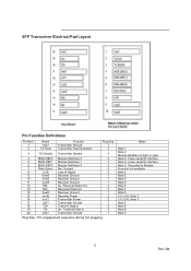
...up within the SFP module. 6) RD-/+: These are AC-coupled, differential lines with DC resistance of Signal) is done inside the module. When high, this output indicates the received optical power is used for further details). VccR and VccT may be internally connected within the SFP transceiver module. 8) TD... sensitivity (as 3.3V ±5% at the user SERDES. They should be used , hot plugging of the SFP transceiver module will accept differential swings of 500 - 2400 mV (250 - 1200 mV single-ended), though it is recommended that the module is present Mod-Def 1 is the clock ...
...up within the SFP module. 6) RD-/+: These are AC-coupled, differential lines with DC resistance of Signal) is done inside the module. When high, this output indicates the received optical power is used for further details). VccR and VccT may be internally connected within the SFP transceiver module. 8) TD... sensitivity (as 3.3V ±5% at the user SERDES. They should be used , hot plugging of the SFP transceiver module will accept differential swings of 500 - 2400 mV (250 - 1200 mV single-ended), though it is recommended that the module is present Mod-Def 1 is the clock ...
AGM731F Product specification
Page 7
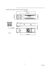
Package Outline Drawing for Metal Housing with Bail de-latch AGM731F 850nm 1.25GBd 1000Base-SX / LC Connector Class 1 Laser Proudct R 272-10254-02 Complies with 21 CFR 1040.10 and 1040.11 Made in China 7 Rev. 0A
Package Outline Drawing for Metal Housing with Bail de-latch AGM731F 850nm 1.25GBd 1000Base-SX / LC Connector Class 1 Laser Proudct R 272-10254-02 Complies with 21 CFR 1040.10 and 1040.11 Made in China 7 Rev. 0A
AGM731F Product specification
Page 8
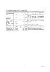
... edge of TX_DISABLE to µsec when the optical output falls below 10% of nominal Time from falling edge of TX_DISABLE to msec when the modulated optical output rises above 90% of nominal From power on or negation of TX_Fault using 300 msec TX Disable. 100 µsec Time from fault...;sec Time from LOS state to Rx LOS assert 100 µsec Time from non-LOS state to Rx LOS deassert 100 kHz 8 Rev. 0A SFP timing parameters for SFP management Parameter TX_DISABLE Assert time Symbol t_off Min.
... edge of TX_DISABLE to µsec when the optical output falls below 10% of nominal Time from falling edge of TX_DISABLE to msec when the modulated optical output rises above 90% of nominal From power on or negation of TX_Fault using 300 msec TX Disable. 100 µsec Time from fault...;sec Time from LOS state to Rx LOS assert 100 µsec Time from non-LOS state to Rx LOS deassert 100 kHz 8 Rev. 0A SFP timing parameters for SFP management Parameter TX_DISABLE Assert time Symbol t_off Min.
AGM731F Product specification
Page 9
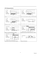
TX_DISABLE negated. Example of initialization during hot plugging, SFP TX_DISABLE timing during hot plugging of SFP TRANSCEIVER. Detection of transmitter safety fault condition Successful recovery from transient safety fault condition Unsuccessful recovery from safety fault condition Timing of LOS detection 9 Rev. 0A SFP timing parameters Power on initialization of SFP transceiver, TX_DISABLE Power on initialization of SFP, TX_DISABLE asserted negated Initialization during normal operation.
TX_DISABLE negated. Example of initialization during hot plugging, SFP TX_DISABLE timing during hot plugging of SFP TRANSCEIVER. Detection of transmitter safety fault condition Successful recovery from transient safety fault condition Unsuccessful recovery from safety fault condition Timing of LOS detection 9 Rev. 0A SFP timing parameters Power on initialization of SFP transceiver, TX_DISABLE Power on initialization of SFP, TX_DISABLE asserted negated Initialization during normal operation.
AGM731F Product specification
Page 10
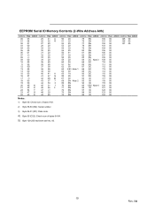
... 74 SN 99 00 124 00 Notes: 1) Byte 63: Check sum of bytes 0-62. 2) Byte 68-83 (SN): Serial number. 3) Byte 84-91 (DC): Date code. 4) Byte 95 (CS2): Check sum of bytes 64-94. 5) Byte 128-255 had been set hex. 00. 10 Rev. 0A
... 74 SN 99 00 124 00 Notes: 1) Byte 63: Check sum of bytes 0-62. 2) Byte 68-83 (SN): Serial number. 3) Byte 84-91 (DC): Date code. 4) Byte 95 (CS2): Check sum of bytes 64-94. 5) Byte 128-255 had been set hex. 00. 10 Rev. 0A
AGM731F Product specification
Page 11
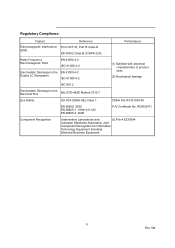
... Electromagnetic Field EN 61000-4-3 IEC 61000-4-3 Electrostatic Discharge to the EN 61000-4-2 Duplex LC Receptacle IEC 61000-4-2 IEC 801.2 (1) Satisfied with electrical characteristics of product spec. (2) No physical damage Electrostatic Discharge to the Electrical Pins MIL-STD-883E Method 3015.7 Eye Safety US FDA CDRH AEL Class 1 CDRH File # 0321539-00...
... Electromagnetic Field EN 61000-4-3 IEC 61000-4-3 Electrostatic Discharge to the EN 61000-4-2 Duplex LC Receptacle IEC 61000-4-2 IEC 801.2 (1) Satisfied with electrical characteristics of product spec. (2) No physical damage Electrostatic Discharge to the Electrical Pins MIL-STD-883E Method 3015.7 Eye Safety US FDA CDRH AEL Class 1 CDRH File # 0321539-00...

AGM731F Product specification
Page 12
Other brand names mentioned herein are trademarks of their respective holder(s). Information is subject to change without notice. All rights reserved. © 2008 NETGEAR, Inc. in the United States and/or other countries. D-AGM731F-0 NETGEAR, the NETGEAR Logo, NETGEAR Digital Entertainer Logo, Connect with Innovation, FrontView, IntelliFi, PowerShift, ProSafe, RAIDar, RAIDiator, X-RAID, RangeMax, ReadyNAS and Smart Wizard are for identification purposes only and may be trademarks of NETGEAR, Inc.
Other brand names mentioned herein are trademarks of their respective holder(s). Information is subject to change without notice. All rights reserved. © 2008 NETGEAR, Inc. in the United States and/or other countries. D-AGM731F-0 NETGEAR, the NETGEAR Logo, NETGEAR Digital Entertainer Logo, Connect with Innovation, FrontView, IntelliFi, PowerShift, ProSafe, RAIDar, RAIDiator, X-RAID, RangeMax, ReadyNAS and Smart Wizard are for identification purposes only and may be trademarks of NETGEAR, Inc.