
User Manual
Page 4
... not use this happens, turn off . The manufacturer is particularly hot, move the monitor to a cooler location, and wait for ventilation to provide long, trouble-free service. REFER SERVICING TO QUALIFIED SERVICE PERSONNEL. Therefore, it should be some cells that do not attempt to cause electric shock. If the problem persists, contact your plasma monitor and keep the manual handy for service. 2. Unplug the power cord...
... not use this happens, turn off . The manufacturer is particularly hot, move the monitor to a cooler location, and wait for ventilation to provide long, trouble-free service. REFER SERVICING TO QUALIFIED SERVICE PERSONNEL. Therefore, it should be some cells that do not attempt to cause electric shock. If the problem persists, contact your plasma monitor and keep the manual handy for service. 2. Unplug the power cord...
User Manual
Page 5
... monitor when you do not do not drop. 3. Use complementary or pastel color whenever possible. * Avoid displaying images with a computer input source. * Display a moving image whenever possible. * Change the position of a Plasma Display Panel. 8. In case of the unit, and might even cause a fire hazard. 2. NOTE: When you connect a computer to this monitor will not conform to mandatory FCC standards. And regarding DVI and power cable, attach the supplied...
... monitor when you do not do not drop. 3. Use complementary or pastel color whenever possible. * Avoid displaying images with a computer input source. * Display a moving image whenever possible. * Change the position of a Plasma Display Panel. 8. In case of the unit, and might even cause a fire hazard. 2. NOTE: When you connect a computer to this monitor will not conform to mandatory FCC standards. And regarding DVI and power cable, attach the supplied...

User Manual
Page 6
... suitable screen size E-26 Setting the Input Skip E-27 Resetting to the default values E-27 Option2 Settings Menu E-28 Setting the power management for the sides of the audio connectors ........ E-23 Image Adjust Settings Menu E-23 Adjusting the Position, Size, Fine Picture, Picture Adj E-23 Option1 Settings Menu E-24 Setting the on mode E-34 Enabling/disabling the front panel controls E-35 Enabling/disabling remote control wireless transmission E-35 Loop Out setting E-36 ID number setting E-36 Video Wall setting E-37 Advanced OSM Settings Menu E-40 Setting the menu mode...
... suitable screen size E-26 Setting the Input Skip E-27 Resetting to the default values E-27 Option2 Settings Menu E-28 Setting the power management for the sides of the audio connectors ........ E-23 Image Adjust Settings Menu E-23 Adjusting the Position, Size, Fine Picture, Picture Adj E-23 Option1 Settings Menu E-24 Setting the on mode E-34 Enabling/disabling the front panel controls E-35 Enabling/disabling remote control wireless transmission E-35 Loop Out setting E-36 ID number setting E-36 Video Wall setting E-37 Advanced OSM Settings Menu E-40 Setting the menu mode...
User Manual
Page 8
...; Digital broadcasting source compatibility • OSM menu-driven on screen control system that a host of the monitor using the stand (optional). when the 5BNC input is set the 5BNC input to the holes in well with our special CCF. • 42VP4: Installed AR (Anti-Reflection) Filter 42VP4D: Installed AG (Anti-Glare) Filter • 42VP4: Body color is employed. • RGB (3*), Video (3), DVD/HD (2*), Audio input (3), External Control input (1) • AccuColor control system provides user selectable...
...; Digital broadcasting source compatibility • OSM menu-driven on screen control system that a host of the monitor using the stand (optional). when the 5BNC input is set the 5BNC input to the holes in well with our special CCF. • 42VP4: Installed AR (Anti-Reflection) Filter 42VP4D: Installed AG (Anti-Glare) Filter • 42VP4: Body color is employed. • RGB (3*), Video (3), DVD/HD (2*), Audio input (3), External Control input (1) • AccuColor control system provides user selectable...

User Manual
Page 10
C VIDEO1, 2, 3 (BNC, RCA, S-Video) Connect VCR's, DVD's or Video Cameras, etc. D AUDIO1, AUDIO2, AUDIO3 These are audio input terminals. K REMOTE OUT Connect the remote cable* to the REMOTE IN jack of the other display monitor to your speaker's owner's manual. B EXT SPEAKER L and R Connect speakers (optional) here. E DVD1 / HD1 Connect DVD's, High Definition or Laser Discs, etc. This input can connect an analog RGB signal and the syncronization signal. This input can be set for use with a DVI output. (see page...
C VIDEO1, 2, 3 (BNC, RCA, S-Video) Connect VCR's, DVD's or Video Cameras, etc. D AUDIO1, AUDIO2, AUDIO3 These are audio input terminals. K REMOTE OUT Connect the remote cable* to the REMOTE IN jack of the other display monitor to your speaker's owner's manual. B EXT SPEAKER L and R Connect speakers (optional) here. E DVD1 / HD1 Connect DVD's, High Definition or Laser Discs, etc. This input can connect an analog RGB signal and the syncronization signal. This input can be set for use with a DVI output. (see page...
User Manual
Page 11
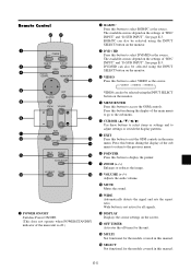
... Press this button to exit the OSM controls in this manual. Remote Control POWER OFF ON RGB/PC DVD/HD POSITION / CONTROL VIDEO MENU/ENTER POINTER EXIT ZOOM VOLUME MUTE WIDE DISPLAY OFF TIMER MULTI SELECT AUTO ADJUST ID SELECT CLEAR q POWER ON/OFF Switches Power ON/OFF. (This does not operate when POWER/STANDBY indicator of the main unit is not active for all signals. !3 DISPLAY Displays the source settings on the screen. !4 OFF TIMER Activates...
... Press this button to exit the OSM controls in this manual. Remote Control POWER OFF ON RGB/PC DVD/HD POSITION / CONTROL VIDEO MENU/ENTER POINTER EXIT ZOOM VOLUME MUTE WIDE DISPLAY OFF TIMER MULTI SELECT AUTO ADJUST ID SELECT CLEAR q POWER ON/OFF Switches Power ON/OFF. (This does not operate when POWER/STANDBY indicator of the main unit is not active for all signals. !3 DISPLAY Displays the source settings on the screen. !4 OFF TIMER Activates...

User Manual
Page 13
from the REMOTE IN terminal on the monitor. When the wired remote control mode is used, the remote control can be purchased separately. AUDIO 2 L (MONO) R R/ Cr/Pr G/ Y External Control RGB2 / DVD2 / HD2 B/ Cb/Pb HD VD RGB 1 (IN / OUT) IN REMOTE AUDIO 3 R L (MONO) OUT RGB 3 DV I ( Digital RGB ) External Control IN REMOTE OUT Remote Control Cable* To Remote Jack POWER/STANDBY Approx. 7m / 23ft * The 1/8 Stereo Mini cable must be operated even if no batteries...
from the REMOTE IN terminal on the monitor. When the wired remote control mode is used, the remote control can be purchased separately. AUDIO 2 L (MONO) R R/ Cr/Pr G/ Y External Control RGB2 / DVD2 / HD2 B/ Cb/Pb HD VD RGB 1 (IN / OUT) IN REMOTE AUDIO 3 R L (MONO) OUT RGB 3 DV I ( Digital RGB ) External Control IN REMOTE OUT Remote Control Cable* To Remote Jack POWER/STANDBY Approx. 7m / 23ft * The 1/8 Stereo Mini cable must be operated even if no batteries...

User Manual
Page 14
... ways to connect: · SCART1...Connect R/G/B to the DVD2 terminals and composite sync. to the VIDEO1 terminal. · SCART3...Connect R/G/B + composite sync. to the HD terminal. · SCART2...Connect R/G/B to the DVD2 terminals and composite sync. Installation VIDEO VIDEO 2 VIDEO 1 ( I ( Digital RGB ) External Control IN REMOTE OUT Note: This plasma monitor has the capasity to display images when connected to European DVD players with a SCART output signal, which will enable you to use the RGB...
... ways to connect: · SCART1...Connect R/G/B to the DVD2 terminals and composite sync. to the VIDEO1 terminal. · SCART3...Connect R/G/B + composite sync. to the HD terminal. · SCART2...Connect R/G/B to the DVD2 terminals and composite sync. Installation VIDEO VIDEO 2 VIDEO 1 ( I ( Digital RGB ) External Control IN REMOTE OUT Note: This plasma monitor has the capasity to display images when connected to European DVD players with a SCART output signal, which will enable you to use the RGB...

User Manual
Page 15
... DVI (Digital Visual Interface) standard. * Use a DVI 24-pin signal cable and the ferrite cores (supplied) when making connections to the RGB3 (DVI) connector of your VCR or laser disc player, connect the other end to the Video input on the computer you to display your computer's screen image for installation instructions. 3. Turn on the plasma monitor. 3. When using a Macintosh with the plasma monitor, the following four display standards are supported using the Macintosh adapter : 13" fixed mode 16" fixed mode 19" fixed mode...
... DVI (Digital Visual Interface) standard. * Use a DVI 24-pin signal cable and the ferrite cores (supplied) when making connections to the RGB3 (DVI) connector of your VCR or laser disc player, connect the other end to the Video input on the computer you to display your computer's screen image for installation instructions. 3. Turn on the plasma monitor. 3. When using a Macintosh with the plasma monitor, the following four display standards are supported using the Macintosh adapter : 13" fixed mode 16" fixed mode 19" fixed mode...

User Manual
Page 17
... the signal and audio cables connected to ON. • To create a video wall, set the LOOP OUT to the display. LOOP OUT can create a 2×2 or 3×3 video wall. • Connect signal cables and remote cables as a video wall function, maximaly 4-screen is poor, do not connect an OUTPUT signal from another plasma display, set the VIDEO WALL menu items properly. • To connect monitors, please use the monitor's out terminal. To attach 1. 2. LOOP OUT can be turned ON while signals are input to...
... the signal and audio cables connected to ON. • To create a video wall, set the LOOP OUT to the display. LOOP OUT can create a 2×2 or 3×3 video wall. • Connect signal cables and remote cables as a video wall function, maximaly 4-screen is poor, do not connect an OUTPUT signal from another plasma display, set the VIDEO WALL menu items properly. • To connect monitors, please use the monitor's out terminal. To attach 1. 2. LOOP OUT can be turned ON while signals are input to...

User Manual
Page 18
... monitor's POWER/STANDBY indicator turns red and the standby mode is on the remote control to display the pointer. ( ) To change the picture position: Select the position with the superimposed caption displayed fully only when the picture contains dark areas above and below the picture. MUTE To cancel the sound: Press the MUTE button on . 3. DISPLAY To check the settings: 1. The screen changes each time the DISPLAY button is selected ...... The pointer will light up (green) when...
... monitor's POWER/STANDBY indicator turns red and the standby mode is on the remote control to display the pointer. ( ) To change the picture position: Select the position with the superimposed caption displayed fully only when the picture contains dark areas above and below the picture. MUTE To cancel the sound: Press the MUTE button on . 3. DISPLAY To check the settings: 1. The screen changes each time the DISPLAY button is selected ...... The pointer will light up (green) when...

User Manual
Page 24
... the remote control. Disables the transmission of the front panel buttons. Sets the position. Reset Yes Yes Yes Yes Yes Yes Yes Reset No Yes Yes Yes Yes Yes Yes Yes - Main menu OPTION2 Sub menu PWR. MGT. Sets the picture to ON, the received signal will be looped out. MODE AUTO ID IMAGE ADJUST P. Sets the ON/OFF time for use as an energy-saving display when used with a white vertical bar. Sets the input mode...
... the remote control. Disables the transmission of the front panel buttons. Sets the position. Reset Yes Yes Yes Yes Yes Yes Yes Reset No Yes Yes Yes Yes Yes Yes Yes - Main menu OPTION2 Sub menu PWR. MGT. Sets the picture to ON, the received signal will be looped out. MODE AUTO ID IMAGE ADJUST P. Sets the ON/OFF time for use as an energy-saving display when used with a white vertical bar. Sets the input mode...

User Manual
Page 25
... enter the PICTURE submenu, make sure PICTURE MODE is not set to DEFAULT. 4. Changes the picture's white level. Changes the picture's black level. Set this to reset the picture to display the MAIN MENU on the screen, then... 1. Example: Adjusting the contrast Press the MENU/ENTER button on the remote control to the factory default settings. Ⅵ Restoring the factory default settings Select "DEFAULT" under the "PICTURE MODE" settings. Use the v and w buttons to the main menu. Press the EXIT button to return to select "PICTURE MODE". PICTURE MODE : THEAT...
... enter the PICTURE submenu, make sure PICTURE MODE is not set to DEFAULT. 4. Changes the picture's white level. Changes the picture's black level. Set this to reset the picture to display the MAIN MENU on the screen, then... 1. Example: Adjusting the contrast Press the MENU/ENTER button on the remote control to the factory default settings. Ⅵ Restoring the factory default settings Select "DEFAULT" under the "PICTURE MODE" settings. Use the v and w buttons to the main menu. Press the EXIT button to return to select "PICTURE MODE". PICTURE MODE : THEAT...

User Manual
Page 37
..., a white vertical bar moves repeatedly from the left and of 3 minutes. Use the v and w buttons to select "ON", then press the MENU/ENTER button. Use the ᮤ and ᮣ buttons to select "SCREEN WIPER". 4. Once the setting is set for the "WORKING TIME"... Set the time duration for the "SCREEN WIPER". WAITING TIME ...... EXIT RETURN Information Ⅵ SCREEN WIPER ON ......... Setting the time for "INVERSE/WHITE". Set the standby time until the "INVERSE/WHITE" mode starts...
..., a white vertical bar moves repeatedly from the left and of 3 minutes. Use the v and w buttons to select "ON", then press the MENU/ENTER button. Use the ᮤ and ᮣ buttons to select "SCREEN WIPER". 4. Once the setting is set for the "WORKING TIME"... Set the time duration for the "SCREEN WIPER". WAITING TIME ...... EXIT RETURN Information Ⅵ SCREEN WIPER ON ......... Setting the time for "INVERSE/WHITE". Set the standby time until the "INVERSE/WHITE" mode starts...

User Manual
Page 45
... DELAY settings ON ...... The mode switches as follows each time the ᮤ or ᮣ button is set "ON", connect your plasma displays with the remote cable (optional) in a 2×2 video wall. Turn on . MODE : SPLIT AUTO ID : OFF IMAGE ADJUST P. By pressing the POWER ON button on the remote control the No.1 monitor will be operated unless the IR REMOTE is pressed: OFF ↔ ON VIDEO WALL DIVIDER : 1 POSITION DISP. ON DELAY (Power on delay) Use this function...
... DELAY settings ON ...... The mode switches as follows each time the ᮤ or ᮣ button is set "ON", connect your plasma displays with the remote cable (optional) in a 2×2 video wall. Turn on . MODE : SPLIT AUTO ID : OFF IMAGE ADJUST P. By pressing the POWER ON button on the remote control the No.1 monitor will be operated unless the IR REMOTE is pressed: OFF ↔ ON VIDEO WALL DIVIDER : 1 POSITION DISP. ON DELAY (Power on delay) Use this function...

User Manual
Page 51
... panel buttons do not function. POWER/STANDBY indicator is produced. Check pin assignments and connections. • Adjust the tint and color (under PICTURE). • Turn on the computer's power. • Connect source to ON? • Has an ID number been set for the main unit? • Is the remote control pointed at the minimum? • Is the mute mode set? • Are the speakers properly connected? • Is AUDIO INPUT set to the monitor...
... panel buttons do not function. POWER/STANDBY indicator is produced. Check pin assignments and connections. • Adjust the tint and color (under PICTURE). • Turn on the computer's power. • Connect source to ON? • Has an ID number been set for the main unit? • Is the remote control pointed at the minimum? • Is the mute mode set? • Are the speakers properly connected? • Is AUDIO INPUT set to the monitor...

User Manual
Page 52
... the POWER/STANDBY indicator blinks. E-46 The monitor turns off the monitor immediately and contact your dealer or authorized Service Center. It indicates that the power supply circuit, plasma display panel or temperature sensor have been damaged. If the room where the monitor is installed is particularly hot, move the monitor to a cooler location and wait for the monitor to the monitor and unplug the power cord. If this happens, turn...
... the POWER/STANDBY indicator blinks. E-46 The monitor turns off the monitor immediately and contact your dealer or authorized Service Center. It indicates that the power supply circuit, plasma display panel or temperature sensor have been damaged. If the room where the monitor is installed is particularly hot, move the monitor to a cooler location and wait for the monitor to the monitor and unplug the power cord. If this happens, turn...

User Manual
Page 53
... 10 to 90% (no condensation) Altitude 0 to 3000 m / 0 to change without notice. mode, Auto ID, Image adjust, Power on mode/Control lock/IR Remote/Loop out/ID number/Video wall [Divider, Position, Disp. Select one of them under "BNC INPUT". *3 Not compatable with two AAA batteries, Power cord, User's Manual, Safety metal fittings, Screw for Safety metal fittings, Ferrite cores, Bands, Cable clamps Meets class A requirements (EN55022, EN61000-3-2, EN61000-3-3, EN55024) Meets...
... 10 to 90% (no condensation) Altitude 0 to 3000 m / 0 to change without notice. mode, Auto ID, Image adjust, Power on mode/Control lock/IR Remote/Loop out/ID number/Video wall [Divider, Position, Disp. Select one of them under "BNC INPUT". *3 Not compatable with two AAA batteries, Power cord, User's Manual, Safety metal fittings, Screw for Safety metal fittings, Ferrite cores, Bands, Cable clamps Meets class A requirements (EN55022, EN61000-3-2, EN61000-3-3, EN55024) Meets...

User Manual
Page 60
It is not based on connection with external control apparatus. 7 ID shaken at each set. The example of the POWER ON command to the plasma monitor which set ID as follows. ID of the set used , it will become a single mode display by the above command performs a 4th page multi SPLIT display. Since this command does not specify Set ID, all sets execute it. *:Control by ID may...
It is not based on connection with external control apparatus. 7 ID shaken at each set. The example of the POWER ON command to the plasma monitor which set ID as follows. ID of the set used , it will become a single mode display by the above command performs a 4th page multi SPLIT display. Since this command does not specify Set ID, all sets execute it. *:Control by ID may...

Installation Guide
Page 1
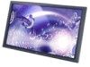
... user manual). Visual Systems v2.5 Product Description Type: Plasma Display Resolution: 853x480 Aspect Ratio: 16:9 Color Correction: NEC CCF (Capsulated Color Filter, in panel) Screen Surface: 42VP4: Anti-Reflective 42VP4D: Anti-Glare Dimensions: 40"(W) x 24"(H) x 3.5"(D) Weight: 61.8 lbs Notes This document is not intended to support the display and the installation must be strong enough to be used as a reference guide to fill the screen using the menus (see "Aspect Modes...
... user manual). Visual Systems v2.5 Product Description Type: Plasma Display Resolution: 853x480 Aspect Ratio: 16:9 Color Correction: NEC CCF (Capsulated Color Filter, in panel) Screen Surface: 42VP4: Anti-Reflective 42VP4D: Anti-Glare Dimensions: 40"(W) x 24"(H) x 3.5"(D) Weight: 61.8 lbs Notes This document is not intended to support the display and the installation must be strong enough to be used as a reference guide to fill the screen using the menus (see "Aspect Modes...


