Installation Guide
Page 1
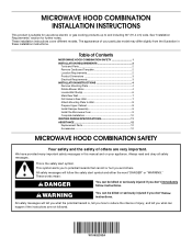
... be killed or seriously injured if you what can happen if the instructions are very important. These installation instructions cover different models. Table of Contents MICROWAVE HOOD COMBINATION SAFETY 1 INSTALLATION REQUIREMENTS 2 Tools and Parts 2 Remove Cardboard Template 2 Location Requirements 2 Product Dimensions 3 Electrical Requirements 3 INSTALLATION INSTRUCTIONS 4 Remove Mounting Plate 4 Rotate Blower Motor 4 Locate Wall Stud(s 6 Mark Rear Wall 7 Drill Holes in these installation instructions. All safety messages will tell you what the potential hazard is, tell...
... be killed or seriously injured if you what can happen if the instructions are very important. These installation instructions cover different models. Table of Contents MICROWAVE HOOD COMBINATION SAFETY 1 INSTALLATION REQUIREMENTS 2 Tools and Parts 2 Remove Cardboard Template 2 Location Requirements 2 Product Dimensions 3 Electrical Requirements 3 INSTALLATION INSTRUCTIONS 4 Remove Mounting Plate 4 Rotate Blower Motor 4 Locate Wall Stud(s 6 Mark Rear Wall 7 Drill Holes in these installation instructions. All safety messages will tell you what the potential hazard is, tell...
Installation Guide
Page 2
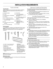
.... Toggle nuts (2) E. 1/4" x 2" lag screws (2) F. Power supply cord bushing (1) H. See "Venting Design Specifications" section. The location must be included. Washers (2) D. See User Instructions.) NOTE: Depending on model, aluminum grease filter and charcoal filter may not be free of packaging) Aluminum grease filters Charcoal filters (Depending on reordering, see "Replacement Parts" section. The piece inside upper cabinet. Check with any obstructions so that the materials used will be sure to use as a rear wall template. 1. Set the cardboard template to the side...
.... Toggle nuts (2) E. 1/4" x 2" lag screws (2) F. Power supply cord bushing (1) H. See "Venting Design Specifications" section. The location must be included. Washers (2) D. See User Instructions.) NOTE: Depending on model, aluminum grease filter and charcoal filter may not be free of packaging) Aluminum grease filters Charcoal filters (Depending on reordering, see "Replacement Parts" section. The piece inside upper cabinet. Check with any obstructions so that the materials used will be sure to use as a rear wall template. 1. Set the cardboard template to the side...

Installation Guide
Page 3
.... Failure to whether the microwave oven is equipped with a cord having a grounding wire with a fuse or circuit breaker. or 20-amp electrical supply with a grounding plug. Grounded 3 prong outlet *30" (76.2 cm) is properly installed and grounded. Do not remove ground prong. GROUNDING INSTRUCTIONS ■ For all governing codes and ordinances. WARNING: Improper use an extension cord. Do not use an extension cord. Required: ■ A 120...
.... Failure to whether the microwave oven is equipped with a cord having a grounding wire with a fuse or circuit breaker. or 20-amp electrical supply with a grounding plug. Grounded 3 prong outlet *30" (76.2 cm) is properly installed and grounded. Do not remove ground prong. GROUNDING INSTRUCTIONS ■ For all governing codes and ordinances. WARNING: Improper use an extension cord. Do not use an extension cord. Required: ■ A 120...
Installation Guide
Page 4
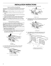
... Slide damper plate toward the front of microwave oven. B A. Screws B. Exhaust port 6. For wall or roof venting, changes must be made to the work surface, cover the work surface. 1. Damper plate 2. Louvered damper vent covers 4 Remove any remaining contents from the microwave oven cavity. 2. Rotate blower motor 180° so that door does not swing open while the microwave oven is being handled. 4. Diagonal wire cutting pliers B. If the mounting plate is being handled. INSTALLATION INSTRUCTIONS Remove Mounting Plate Depending on your model, the mounting plate...
... Slide damper plate toward the front of microwave oven. B A. Screws B. Exhaust port 6. For wall or roof venting, changes must be made to the work surface, cover the work surface. 1. Damper plate 2. Louvered damper vent covers 4 Remove any remaining contents from the microwave oven cavity. 2. Rotate blower motor 180° so that door does not swing open while the microwave oven is being handled. 4. Diagonal wire cutting pliers B. If the mounting plate is being handled. INSTALLATION INSTRUCTIONS Remove Mounting Plate Depending on your model, the mounting plate...

Installation Guide
Page 5
... the rectangular vent covers on the damper plate removed in Step 3. 8. Slots 9. Reattach damper plate. Secure damper plate with 2 screws removed in Step 3 cannot be poor. 5 Securely tighten screws. D A. Screws C. Repeat Step 3 from "Wall Venting Installation Only." 5. Repeat Step 4 from "Wall Venting Installation Only." 4. Screws C. Damper plate tabs D. Diagonal wire cutting pliers B. Exhaust port IMPORTANT: If blower motor is not correctly oriented, the 2 screws removed in Step 1. Reattach blower motor to the microwave oven. 7. Make sure damper plate tabs...
... the rectangular vent covers on the damper plate removed in Step 3. 8. Slots 9. Reattach damper plate. Secure damper plate with 2 screws removed in Step 3 cannot be poor. 5 Securely tighten screws. D A. Screws C. Repeat Step 3 from "Wall Venting Installation Only." 5. Repeat Step 4 from "Wall Venting Installation Only." 4. Screws C. Damper plate tabs D. Diagonal wire cutting pliers B. Exhaust port IMPORTANT: If blower motor is not correctly oriented, the 2 screws removed in Step 1. Reattach blower motor to the microwave oven. 7. Make sure damper plate tabs...
Installation Guide
Page 6
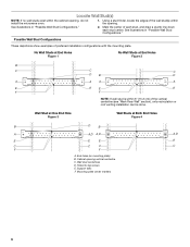
... End Hole Figure 3 Wall Studs at End Holes Figure 2 B C C C D B D A A A A E E E E F F NOTE: If wall stud is within 6" (15.2 cm) of the wall stud(s) within the cabinet opening vertical centerline C. Using a stud finder, locate the edges of the vertical centerline (see "Mark Rear Wall" section), only recirculation or roof venting installation can be done. See illustrations in "Possible Wall Stud Configurations." 2. Support tabs F. End holes (on mounting plate) B.
... End Hole Figure 3 Wall Studs at End Holes Figure 2 B C C C D B D A A A A E E E E F F NOTE: If wall stud is within 6" (15.2 cm) of the wall stud(s) within the cabinet opening vertical centerline C. Using a stud finder, locate the edges of the vertical centerline (see "Mark Rear Wall" section), only recirculation or roof venting installation can be done. See illustrations in "Possible Wall Stud Configurations." 2. Support tabs F. End holes (on mounting plate) B.
Installation Guide
Page 7
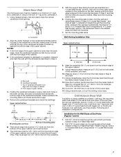
... are 3 installation configurations. Wall Venting Installation Only Upper cabinet bottom ³⁄₈" (1 cm) 4" (10.2 cm) Centerline 6" (15.2 cm) 6" (15.2 cm) 8. Using measuring tape, measure out 6" (15.2 cm) on a level line with the dimensions described in Step 6 of the cutout area. 14. Drill 3/16" (5 mm) hole(s) into the wall stud(s) at both holes in "Locate Wall Stud(s)" section), align the mounting plate center markers...
... are 3 installation configurations. Wall Venting Installation Only Upper cabinet bottom ³⁄₈" (1 cm) 4" (10.2 cm) Centerline 6" (15.2 cm) 6" (15.2 cm) 8. Using measuring tape, measure out 6" (15.2 cm) on a level line with the dimensions described in Step 6 of the cutout area. 14. Drill 3/16" (5 mm) hole(s) into the wall stud(s) at both holes in "Locate Wall Stud(s)" section), align the mounting plate center markers...

Installation Guide
Page 8
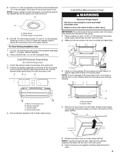
... open . 3. Securely tighten the lag screws. Place Upper Cabinet Template against the rear wall so that it , trim the template edges so that the holes cut into the wall stud at both end holes drilled into the wall studs and/or drywall using either 1/4-20 x 3" round-head bolts and toggle nuts or 1/4 x 2" lag screws. B D A. 1/4-20 x 3" round-head bolt B. With the support tabs of the mounting plate...
... open . 3. Securely tighten the lag screws. Place Upper Cabinet Template against the rear wall so that it , trim the template edges so that the holes cut into the wall stud at both end holes drilled into the wall studs and/or drywall using either 1/4-20 x 3" round-head bolts and toggle nuts or 1/4 x 2" lag screws. B D A. 1/4-20 x 3" round-head bolt B. With the support tabs of the mounting plate...
Installation Guide
Page 9
5. Install Damper Assembly (for the power supply cord. A B C D Install the Microwave Oven WARNING Excessive Weight Hazard Use two or more people, lift microwave oven and hang it on support tabs at the bottom of the shaded rectangular area "F" on Upper Cabinet Template. 8. IMPORTANT: The control side of microwave oven B. A B A. Mounting plate B. Make sure the microwave oven door is at points "D" and "E" on the back of the upper cabinet. 5. Back of the microwave oven is for wall venting only) 1. Sheet metal...
5. Install Damper Assembly (for the power supply cord. A B C D Install the Microwave Oven WARNING Excessive Weight Hazard Use two or more people, lift microwave oven and hang it on support tabs at the bottom of the shaded rectangular area "F" on Upper Cabinet Template. 8. IMPORTANT: The control side of microwave oven B. A B A. Mounting plate B. Make sure the microwave oven door is at points "D" and "E" on the back of the upper cabinet. 5. Back of the microwave oven is for wall venting only) 1. Sheet metal...
Installation Guide
Page 10
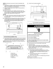
... the damper assembly slides under vent) Complete Installation 1. NOTE: The screw cannot be added. Sheet metal screw D. Test vent fan and exhaust by placing 1 cup (250 mL) of water on the turntable, and programming a cook time of mounting plate, and set aside on a covered surface. 8. Loosen mounting plate screws. Tighten bolts until there is required, rotate microwave oven downward. Vent B. Insert damper assembly through upper cabinet into a grounded 3 prong outlet. ■ See the User Instructions for troubleshooting information. Upper cabinet cutout E. Failure...
... the damper assembly slides under vent) Complete Installation 1. NOTE: The screw cannot be added. Sheet metal screw D. Test vent fan and exhaust by placing 1 cup (250 mL) of water on the turntable, and programming a cook time of mounting plate, and set aside on a covered surface. 8. Loosen mounting plate screws. Tighten bolts until there is required, rotate microwave oven downward. Vent B. Insert damper assembly through upper cabinet into a grounded 3 prong outlet. ■ See the User Instructions for troubleshooting information. Upper cabinet cutout E. Failure...

Installation Guide
Page 11
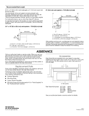
... performance ■ using uniformly sized vents ■ using duct tape to round transition piece F. For optimal venting installation, we recommend: ■ using roof or wall caps that have back draft dampers ■ using a rigid metal vent ■ using the most direct route by minimizing the length of the vent and number of the microwave oven and the rectangular to vent air outside, unless using recirculation installation. Elbow (for wall venting only) D. VENTING DESIGN SPECIFICATIONS This section...
... performance ■ using uniformly sized vents ■ using duct tape to round transition piece F. For optimal venting installation, we recommend: ■ using roof or wall caps that have back draft dampers ■ using a rigid metal vent ■ using the most direct route by minimizing the length of the vent and number of the microwave oven and the rectangular to vent air outside, unless using recirculation installation. Elbow (for wall venting only) D. VENTING DESIGN SPECIFICATIONS This section...
Installation Guide
Page 12
... opening , behind the door. ■ Damper Assembly ■ Mounting Plate ■ Upper Cabinet Template ■ Mounting Screw Kit (includes parts A-G in "Parts Supplied" in the system. See "Recommended Standard Fittings" section for details. See the following examples: 3¹⁄₄" x 10" (8.3 x 25.4 cm) vent system = 73 ft (22.2 m) total A B 6 ft (1.8 m) 2 ft (0.6 m) C A. When you call, you need additional assistance, call us at our toll free number listed in the User Instructions...
... opening , behind the door. ■ Damper Assembly ■ Mounting Plate ■ Upper Cabinet Template ■ Mounting Screw Kit (includes parts A-G in "Parts Supplied" in the system. See "Recommended Standard Fittings" section for details. See the following examples: 3¹⁄₄" x 10" (8.3 x 25.4 cm) vent system = 73 ft (22.2 m) total A B 6 ft (1.8 m) 2 ft (0.6 m) C A. When you call, you need additional assistance, call us at our toll free number listed in the User Instructions...

Warranty Information
Page 1
... operator instructions and/or installation instructions. 4. Repairs to parts or systems resulting from unauthorized modifications made to repair or replace appliance light bulbs or filters. If outside the 50 United States and Canada, contact your correspondence. If you need assistance using your major appliance is used in the country in which it is installed in accordance with the removal from your model number and serial number on the label located on the Magnetron...
... operator instructions and/or installation instructions. 4. Repairs to parts or systems resulting from unauthorized modifications made to repair or replace appliance light bulbs or filters. If outside the 50 United States and Canada, contact your correspondence. If you need assistance using your major appliance is used in the country in which it is installed in accordance with the removal from your model number and serial number on the label located on the Magnetron...
Use & Care Guide
Page 1
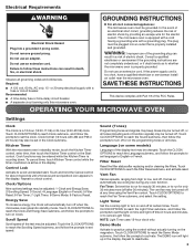
... the provided Installation Instructions. WARNING You can be killed or seriously injured if you don't follow instructions. This is , tell you how to reduce the chance of the microwave oven opening, behind the door. All safety messages will follow the specific "PRECAUTIONS TO AVOID POSSIBLE EXPOSURE TO EXCESSIVE MICROWAVE ENERGY" found in this manual and on your model and serial number located on the...
... the provided Installation Instructions. WARNING You can be killed or seriously injured if you don't follow instructions. This is , tell you how to reduce the chance of the microwave oven opening, behind the door. All safety messages will follow the specific "PRECAUTIONS TO AVOID POSSIBLE EXPOSURE TO EXCESSIVE MICROWAVE ENERGY" found in this manual and on your model and serial number located on the...

Use & Care Guide
Page 2
... not mount over edge of California to the State of table or counter. ■ See door surface cleaning instructions in oven. - IMPORTANT SAFETY INSTRUCTIONS ■ Use the microwave oven only for examination, repair, or adjustment. ■ Do not cover or block any openings on the microwave oven. ■ Do not store this oven with narrow necks. - If materials inside the oven to facilitate cooking. ■ Suitable for example, near a kitchen sink...
... not mount over edge of California to the State of table or counter. ■ See door surface cleaning instructions in oven. - IMPORTANT SAFETY INSTRUCTIONS ■ Use the microwave oven only for examination, repair, or adjustment. ■ Do not cover or block any openings on the microwave oven. ■ Do not store this oven with narrow necks. - If materials inside the oven to facilitate cooking. ■ Suitable for example, near a kitchen sink...
Use & Care Guide
Page 3
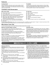
... prompts to reach the Light Timer submenu, and follow these instructions can result in a risk of the FCC Rules. Sound (Tones) Programming tones and signals. Touch CLOCK/OPTIONS to set speed. Demo Mode Activate to whether the microwave oven is counting down. Do not use an extension cord. or 20-amp electrical supply with a grounding plug. The vent fan may be changed. Electrical Requirements WARNING GROUNDING INSTRUCTIONS Electrical Shock Hazard Plug into...
... prompts to reach the Light Timer submenu, and follow these instructions can result in a risk of the FCC Rules. Sound (Tones) Programming tones and signals. Touch CLOCK/OPTIONS to set speed. Demo Mode Activate to whether the microwave oven is counting down. Do not use an extension cord. or 20-amp electrical supply with a grounding plug. The vent fan may be changed. Electrical Requirements WARNING GROUNDING INSTRUCTIONS Electrical Shock Hazard Plug into...
Use & Care Guide
Page 4
... display. wire mesh side up the other end, and slide it toward the tab area. ■ Charcoal filters: The charcoal filters are side by side. To avoid damage to soil buildup, keep cavity, microwave inlet cover, cooking rack supports, and area where the door touches the frame clean. Cookware and Dinnerware Turntable Turntable may be changed . Make sure microwave oven has been plugged in microwave oven with plates that are behind the vent grille...
... display. wire mesh side up the other end, and slide it toward the tab area. ■ Charcoal filters: The charcoal filters are side by side. To avoid damage to soil buildup, keep cavity, microwave inlet cover, cooking rack supports, and area where the door touches the frame clean. Cookware and Dinnerware Turntable Turntable may be changed . Make sure microwave oven has been plugged in microwave oven with plates that are behind the vent grille...
Use & Care Guide
Page 5
Remove two screws on cavity walls, microwave inlet cover, cooking rack supports, and area where the door touches the frame can cause arcing. Please refer to avoid unintended starting of the microwave oven. If a household fuse has blown or a circuit breaker has tripped, replace the fuse or reset the circuit breaker. Try to cool the microwave oven. If a message about the door appears in "Microwave Oven Care" section. Open and close door. Arcing in the bullets below is set properly...
Remove two screws on cavity walls, microwave inlet cover, cooking rack supports, and area where the door touches the frame can cause arcing. Please refer to avoid unintended starting of the microwave oven. If a household fuse has blown or a circuit breaker has tripped, replace the fuse or reset the circuit breaker. Try to cool the microwave oven. If a message about the door appears in "Microwave Oven Care" section. Open and close door. Arcing in the bullets below is set properly...
Use & Care Guide
Page 6
... specified replacement Magnetron to correct non-cosmetic defects in materials or workmanship in materials or workmanship and is covered by a Maytag designated service company. You can write to Maytag with electrical or plumbing codes, or use of original purchase, when this User Guide and model number information for repairs. This warranty gives you specific legal rights, and you . Please keep this major appliance is installed, operated and maintained...
... specified replacement Magnetron to correct non-cosmetic defects in materials or workmanship in materials or workmanship and is covered by a Maytag designated service company. You can write to Maytag with electrical or plumbing codes, or use of original purchase, when this User Guide and model number information for repairs. This warranty gives you specific legal rights, and you . Please keep this major appliance is installed, operated and maintained...


