
Installation Instructions
Page 1
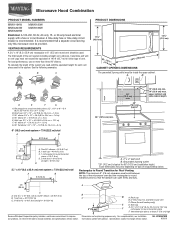
... in Rear Wall 7 Attach Mounting Plate to and including 36" (91.4 cm) wide. See "Installation Requirements" section for use above electric or gas cooking products up to Wall 8 Prepare Upper Cabinet 8 Install Damper Assembly 9 Install the Microwave Oven 9 Complete Installation 10 VENTING DESIGN SPECIFICATIONS 11 ASSISTANCE 12 Replacement Parts 12 Accessories 12 MICROWAVE HOOD COMBINATION SAFETY Your safety and the safety of your appliance. Always read and obey all safety messages. W10344702B These installation instructions cover different models.
... in Rear Wall 7 Attach Mounting Plate to and including 36" (91.4 cm) wide. See "Installation Requirements" section for use above electric or gas cooking products up to Wall 8 Prepare Upper Cabinet 8 Install Damper Assembly 9 Install the Microwave Oven 9 Complete Installation 10 VENTING DESIGN SPECIFICATIONS 11 ASSISTANCE 12 Replacement Parts 12 Accessories 12 MICROWAVE HOOD COMBINATION SAFETY Your safety and the safety of your appliance. Always read and obey all safety messages. W10344702B These installation instructions cover different models.

Installation Instructions
Page 2
... to round transition piece, the 3" (7.6 cm) clearance needs to use as a rear wall template. 1. Power supply cord bushing (1) H. See "Venting Design Specifications" section. Set the cardboard template to the side and refer to it during the "Mark Rear Wall" part of wall structures, be sure to exist above the microwave oven so that the materials used will be free of any tools listed here. ■ Measuring tape ■ Stud finder ■...
... to round transition piece, the 3" (7.6 cm) clearance needs to use as a rear wall template. 1. Power supply cord bushing (1) H. See "Venting Design Specifications" section. Set the cardboard template to the side and refer to it during the "Mark Rear Wall" part of wall structures, be sure to exist above the microwave oven so that the materials used will be free of any tools listed here. ■ Measuring tape ■ Stud finder ■...

Installation Instructions
Page 3
... an electrical short circuit, grounding reduces the risk of range/cooktop below. SAVE THESE INSTRUCTIONS 3 Observe all cord connected appliances: The microwave oven must be grounded. A. 2" x 4" wall stud B. Grounded 3 prong outlet *30" (76.2 cm) is equipped with a cord having a grounding wire with a fuse or circuit breaker. If the power supply cord is properly installed and grounded. Do not use an extension cord. or 20-amp electrical supply with a grounding plug. A B Electrical...
... an electrical short circuit, grounding reduces the risk of range/cooktop below. SAVE THESE INSTRUCTIONS 3 Observe all cord connected appliances: The microwave oven must be grounded. A. 2" x 4" wall stud B. Grounded 3 prong outlet *30" (76.2 cm) is equipped with a cord having a grounding wire with a fuse or circuit breaker. If the power supply cord is properly installed and grounded. Do not use an extension cord. or 20-amp electrical supply with a grounding plug. A B Electrical...

Installation Instructions
Page 4
... not swing open while the microwave oven is reinstalled in recessed holes) D A. For wall or roof venting, changes must be made to the microwave oven, do not grip or use the door or door handle while the microwave oven is set aside. 3. Reattach damper plate. Screws C. Damper plate 2. A A. Damper plate tabs D. Blower motor 5. Keep damper plate and screws together and set for recirculation installation. Remove 2 screws attaching blower motor to back of the microwave oven and lift up. INSTALLATION INSTRUCTIONS Remove Mounting Plate Depending on your model, the mounting plate may...
... not swing open while the microwave oven is reinstalled in recessed holes) D A. For wall or roof venting, changes must be made to the microwave oven, do not grip or use the door or door handle while the microwave oven is set aside. 3. Reattach damper plate. Screws C. Damper plate 2. A A. Damper plate tabs D. Blower motor 5. Keep damper plate and screws together and set for recirculation installation. Remove 2 screws attaching blower motor to back of the microwave oven and lift up. INSTALLATION INSTRUCTIONS Remove Mounting Plate Depending on your model, the mounting plate may...

Installation Instructions
Page 5
...microwave oven with 2 screws removed in Step 1 of "Wall Venting Installation Only." 5 Damper plate B. Slots 8. Repeat Step 2 from "Wall Venting Installation Only." 2. A 6. A B C A. Repeat Step 4 from "Wall Venting Installation Only." 4. Lower blower motor back into the slots in Step 3 cannot be poor. D A. Screws C. Repeat Step 3 from "Wall Venting Installation Only." 5. Make sure damper plate tabs are inserted into microwave oven. Exhaust port IMPORTANT: If blower motor is not correctly oriented, the 2 screws removed in the top of microwave oven. Damper plate...
...microwave oven with 2 screws removed in Step 1 of "Wall Venting Installation Only." 5 Damper plate B. Slots 8. Repeat Step 2 from "Wall Venting Installation Only." 2. A 6. A B C A. Repeat Step 4 from "Wall Venting Installation Only." 4. Lower blower motor back into the slots in Step 3 cannot be poor. D A. Screws C. Repeat Step 3 from "Wall Venting Installation Only." 5. Make sure damper plate tabs are inserted into microwave oven. Exhaust port IMPORTANT: If blower motor is not correctly oriented, the 2 screws removed in the top of microwave oven. Damper plate...

Installation Instructions
Page 6
... mounting plate) B. Support tabs F. Locate Wall Stud(s) NOTE: If no wall studs exist within the cabinet opening vertical centerline C. Cabinet opening , do not install the microwave oven. 1. Mark the center of the wall stud(s) within 6" (15.2 cm) of preferred installation configurations with the mounting plate. Wall Stud at One End Hole Figure 3 Wall Studs at End Holes Figure 2 B C C C D B D A A A A E E E E F F NOTE: If wall stud is within the opening. Mounting plate center markers 6 Using a stud finder, locate the...
... mounting plate) B. Support tabs F. Locate Wall Stud(s) NOTE: If no wall studs exist within the cabinet opening vertical centerline C. Cabinet opening , do not install the microwave oven. 1. Mark the center of the wall stud(s) within 6" (15.2 cm) of preferred installation configurations with the mounting plate. Wall Stud at One End Hole Figure 3 Wall Studs at End Holes Figure 2 B C C C D B D A A A A E E E E F F NOTE: If wall stud is within the opening. Mounting plate center markers 6 Using a stud finder, locate the...

Installation Instructions
Page 7
... "Mark Rear Wall." Drill 3/16" (5 mm) hole(s) into the wall stud(s) at End Holes (Figures 1 & 2) 1. Cardboard template C. A A. NOTES: ■ If the front edge of the upper cabinet is lower than the back edge, lower the cardboard template so that the top of the cardboard template is over wall studs, use 1 lag screw and one corner of the cutout area. 14. Set the mounting plate aside. Using measuring tape...
... "Mark Rear Wall." Drill 3/16" (5 mm) hole(s) into the wall stud(s) at End Holes (Figures 1 & 2) 1. Cardboard template C. A A. NOTES: ■ If the front edge of the upper cabinet is lower than the back edge, lower the cardboard template so that the top of the cardboard template is over wall studs, use 1 lag screw and one corner of the cutout area. 14. Set the mounting plate aside. Using measuring tape...

Installation Instructions
Page 8
... or 1/4 x 2" lag screws. Disconnect power to make sure toggle nut has opened against the upper cabinet bottom. Drill a 3/4" (19 mm) hole through both end holes. 3. The template has trim lines to use as guides. ■ If the wall behind the microwave oven (as at Both End Holes (Figure 4) 1. Position mounting plate on the rear wall. Insert a lag screw into both end holes of "Installation for Wall Stud at...
... or 1/4 x 2" lag screws. Disconnect power to make sure toggle nut has opened against the upper cabinet bottom. Drill a 3/4" (19 mm) hole through both end holes. 3. The template has trim lines to use as guides. ■ If the wall behind the microwave oven (as at Both End Holes (Figure 4) 1. Position mounting plate on the rear wall. Insert a lag screw into both end holes of "Installation for Wall Stud at...

Installation Instructions
Page 9
... being handled. Damper assembly C. Mounting plate B. With front of the microwave oven is metal, the supply cord bushing needs to move and install microwave oven. Rotate microwave oven up toward upper cabinet. Cut 3/4" (19 mm) hole at points "D" and "E" on the template. IMPORTANT: The control side of microwave oven still tilted, thread power supply cord through the wall, make sure the damper assembly fits easily into the vent in place. 9 A. Damper blade D. B A A. These are for wall venting only) 1. A B C D Install the Microwave Oven...
... being handled. Damper assembly C. Mounting plate B. With front of the microwave oven is metal, the supply cord bushing needs to move and install microwave oven. Rotate microwave oven up toward upper cabinet. Cut 3/4" (19 mm) hole at points "D" and "E" on the template. IMPORTANT: The control side of microwave oven still tilted, thread power supply cord through the wall, make sure the damper assembly fits easily into the vent in place. 9 A. Damper blade D. B A A. These are for wall venting only) 1. A B C D Install the Microwave Oven...

Installation Instructions
Page 10
... sheet metal screw. Vent B. Bolts For Roof Venting Installation Only 1. Plug microwave oven into a grounded 3 prong outlet. Check the operation of microwave oven by operating the vent fan. 5. Adjust mounting plate and retighten screws. 9. To avoid warping, wood filler blocks (installer to damper assembly. Long tab F. Do not remove ground prong. Replace the fuse or reset the circuit breaker. NOTE: If microwave oven does not need to follow these instructions can result in place, insert bolts through the cabinet cutout...
... sheet metal screw. Vent B. Bolts For Roof Venting Installation Only 1. Plug microwave oven into a grounded 3 prong outlet. Check the operation of microwave oven by operating the vent fan. 5. Adjust mounting plate and retighten screws. 9. To avoid warping, wood filler blocks (installer to damper assembly. Long tab F. Do not remove ground prong. Replace the fuse or reset the circuit breaker. NOTE: If microwave oven does not need to follow these instructions can result in place, insert bolts through the cabinet cutout...
Installation Instructions
Page 11
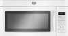
... venting installation, we recommend: ■ using roof or wall caps that have back draft dampers ■ using a rigid metal vent ■ using the most direct route by minimizing the length of the vent and number of elbows to provide efficient performance ■ using uniformly sized vents ■ using duct tape to seal all joints in "Recommended Vent Length." Rectangular to open freely and fully. A B C D E 3" (7.6 cm) F A. Elbow (for the damper...
... venting installation, we recommend: ■ using roof or wall caps that have back draft dampers ■ using a rigid metal vent ■ using the most direct route by minimizing the length of the vent and number of elbows to provide efficient performance ■ using uniformly sized vents ■ using duct tape to seal all joints in "Recommended Vent Length." Rectangular to open freely and fully. A B C D E 3" (7.6 cm) F A. Elbow (for the damper...

Installation Instructions
Page 12
... service center. Accessories Filler Panel Kits are available from sticking. Recommended Vent Length A 3¹⁄₄" x 10" (8.3 x 25.4 cm) rectangular or 6" (15.2 cm) round vent should be found on the model and serial number plate, which is located behind the door. ■ Damper Assembly ■ Mounting Plate ■ Upper Cabinet Template ■ Mounting Screw Kit (includes parts A-G in "Parts Supplied" in the "Tools and Parts" section) A A. See "Recommended Standard Fittings" section for details. Replacement Parts...
... service center. Accessories Filler Panel Kits are available from sticking. Recommended Vent Length A 3¹⁄₄" x 10" (8.3 x 25.4 cm) rectangular or 6" (15.2 cm) round vent should be found on the model and serial number plate, which is located behind the door. ■ Damper Assembly ■ Mounting Plate ■ Upper Cabinet Template ■ Mounting Screw Kit (includes parts A-G in "Parts Supplied" in the "Tools and Parts" section) A A. See "Recommended Standard Fittings" section for details. Replacement Parts...
Owners Manual
Page 1
... need your model and serial number located on your appliance. If you how to potential hazards that can happen if the instructions are able to explode and should experience a problem not covered in the shell and sealed containers - Puede encontrar su número de modelo y de serie en la etiqueta ubicada en la parte frontal de la abertura del horno de microondas...
... need your model and serial number located on your appliance. If you how to potential hazards that can happen if the instructions are able to explode and should experience a problem not covered in the shell and sealed containers - Puede encontrar su número de modelo y de serie en la etiqueta ubicada en la parte frontal de la abertura del horno de microondas...

Owners Manual
Page 2
... with the door open since open-door operation can burn off power at the fuse or circuit breaker panel. - Visible bubbling or boiling when the container is removed from the microwave oven is specifically designed to persons: - After heating, allow soil or cleaner residue to microwave energy. Corrosive cleaning agents, such as water, coffee, or tea are placed inside the oven ignite, keep oven door closed, turn the fan on models with any...
... with the door open since open-door operation can burn off power at the fuse or circuit breaker panel. - Visible bubbling or boiling when the container is removed from the microwave oven is specifically designed to persons: - After heating, allow soil or cleaner residue to microwave energy. Corrosive cleaning agents, such as water, coffee, or tea are placed inside the oven ignite, keep oven door closed, turn the fan on models with any...

Owners Manual
Page 3
...; A time-delay fuse or time-delay circuit breaker. ■ A separate circuit serving only this microwave oven. If the power supply cord is properly grounded. The vent fan may be grounded. Touch the Options or Setup control to reach the "Demo Mode" submenu, and activate or deactivate Demo Mode. Features Cooking Rack Use only for about 3 seconds until 2 tones sound and padlock icon appears in a risk of electric shock. This is helpful when cooking with plates...
...; A time-delay fuse or time-delay circuit breaker. ■ A separate circuit serving only this microwave oven. If the power supply cord is properly grounded. The vent fan may be grounded. Touch the Options or Setup control to reach the "Demo Mode" submenu, and activate or deactivate Demo Mode. Features Cooking Rack Use only for about 3 seconds until 2 tones sound and padlock icon appears in a risk of electric shock. This is helpful when cooking with plates...

Owners Manual
Page 4
... cavity, microwave inlet cover, cooking rack supports, and area where the door touches the frame clean. To reinstall, place the filter into the opening opposite the tab area, swing up , replace vent grille, and secure with screws. ■ Cooktop light: The cooktop light bulb is located on some models) appears in microwave oven with 1 cup (250 mL) of any cycle, "ADD MORE TIME 0:00" appears in oven more than one hour before touching the Start control. Manual Cooking/Stage Cooking Warm...
... cavity, microwave inlet cover, cooking rack supports, and area where the door touches the frame clean. To reinstall, place the filter into the opening opposite the tab area, swing up , replace vent grille, and secure with screws. ■ Cooktop light: The cooktop light bulb is located on some models) appears in microwave oven with 1 cup (250 mL) of any cycle, "ADD MORE TIME 0:00" appears in oven more than one hour before touching the Start control. Manual Cooking/Stage Cooking Warm...

Owners Manual
Page 5
... microwave oven still does not operate, call an electrician. ■ Magnetron Try to avoid unintended starting of the door, remove it, then firmly close door. If a message about the door appears in the display, the door has been closed for assistance. Make sure Demo Mode (on during microwave oven operation to cool the microwave oven's controls while the cooktop below . Arcing in "Microwave Oven Care" section. Reset the clock. ■ A letter followed by a number is set properly. Use a corded...
... microwave oven still does not operate, call an electrician. ■ Magnetron Try to avoid unintended starting of the door, remove it, then firmly close door. If a message about the door appears in the display, the door has been closed for assistance. Make sure Demo Mode (on during microwave oven operation to cool the microwave oven's controls while the cooktop below . Arcing in "Microwave Oven Care" section. Reset the clock. ■ A letter followed by a number is set properly. Use a corded...
Owners Manual
Page 6
... electrical or plumbing codes, or use of consumables or cleaning products not approved by the customer. This major appliance is designed to be easily determined. Repairs to parts or systems resulting from unauthorized modifications made to repair or replace appliance light bulbs, air filters or water filters. Expenses for travel and transportation for product service if your major appliance for future reference. This warranty...
... electrical or plumbing codes, or use of consumables or cleaning products not approved by the customer. This major appliance is designed to be easily determined. Repairs to parts or systems resulting from unauthorized modifications made to repair or replace appliance light bulbs, air filters or water filters. Expenses for travel and transportation for product service if your major appliance for future reference. This warranty...
Dimension Guide
Page 1
... this microwave oven be inside the upper cabinet. For complete details, see Installation our products, we reserve the right to change materials and specifications without notice. Instructions packed with a fuse or circuit breaker. Specifications subject to change without notice. W10344702B 9/30/10 Microwave Hood Combination PRODUCT MODEL NUMBERS MMV1164W MMV4203W MMV5208W MMV6180W MMV6186W Electrical: A 120-Volt, 60-Hz, AC-only, 15- It is recommended that the damper can open freely...
... this microwave oven be inside the upper cabinet. For complete details, see Installation our products, we reserve the right to change materials and specifications without notice. Instructions packed with a fuse or circuit breaker. Specifications subject to change without notice. W10344702B 9/30/10 Microwave Hood Combination PRODUCT MODEL NUMBERS MMV1164W MMV4203W MMV5208W MMV6180W MMV6186W Electrical: A 120-Volt, 60-Hz, AC-only, 15- It is recommended that the damper can open freely...

Warranty Information
Page 1
... published installation instructions. 11. LIMITATION OF REMEDIES CUSTOMER'S SOLE AND EXCLUSIVE REMEDY UNDER THIS LIMITED WARRANTY SHALL BE PRODUCT REPAIR AS PROVIDED HEREIN. If outside the 50 United States and Canada, contact your authorized Maytag dealer to determine if another warranty applies. 9/07 For additional product information or to repair or replace appliance light bulbs, air filters or water filters. For assistance or service...
... published installation instructions. 11. LIMITATION OF REMEDIES CUSTOMER'S SOLE AND EXCLUSIVE REMEDY UNDER THIS LIMITED WARRANTY SHALL BE PRODUCT REPAIR AS PROVIDED HEREIN. If outside the 50 United States and Canada, contact your authorized Maytag dealer to determine if another warranty applies. 9/07 For additional product information or to repair or replace appliance light bulbs, air filters or water filters. For assistance or service...


