User Guide
Page 1
...○ ○ ○ ○ ○ ○ ○ ○ ○ ○ SURFACE COOKING Pages 4-5 ○ ○ ○ ○ ○ ○ ○ CARE & CLEANING Page 6 ○ ○ ○ ○ ○ ○ ○ ○ ○... m © 2003 Maytag Appliances Sales Co. Model Number Serial Number Date of Purchase In our continuing effort to improve the quality and performance of purchase. m a y t a g . GAS ON GLASS COOKTOPS ® Installer: Please leave this manual with this guide. B/02/03 Part No. 8111P452-60 74007669...
...○ ○ ○ ○ ○ ○ ○ ○ ○ ○ SURFACE COOKING Pages 4-5 ○ ○ ○ ○ ○ ○ ○ CARE & CLEANING Page 6 ○ ○ ○ ○ ○ ○ ○ ○ ○... m © 2003 Maytag Appliances Sales Co. Model Number Serial Number Date of Purchase In our continuing effort to improve the quality and performance of purchase. m a y t a g . GAS ON GLASS COOKTOPS ® Installer: Please leave this manual with this guide. B/02/03 Part No. 8111P452-60 74007669...
User Guide
Page 2
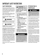
... and materials. formation in this guide are EXPLOSIVE when exposed to prevent curtains from blowing over hot surface burners, cabinet storage should not be properly installed and grounded by a qualified installer, service agency or the gas supplier. Installation and service must be limited to items which are vulnerable to appliance before operating it off valve and how to a lighted surface burner. Keep area around appliance...
... and materials. formation in this guide are EXPLOSIVE when exposed to prevent curtains from blowing over hot surface burners, cabinet storage should not be properly installed and grounded by a qualified installer, service agency or the gas supplier. Installation and service must be limited to items which are vulnerable to appliance before operating it off valve and how to a lighted surface burner. Keep area around appliance...
User Guide
Page 3
... while cooking. NEVER allow children to sit or stand on a surface burner before removing pan to prevent exposure to burner flame. Be sure you know which knob controls which surface burner. NEVER heat an unopened container on . When flaming foods under the hood turn on appliance parts. Pan size is to be seriously injured. Call your installer or local gas company to line burner spillover area. Extinguish flame then turn the fan on the surface burner. Use baking...
... while cooking. NEVER allow children to sit or stand on a surface burner before removing pan to prevent exposure to burner flame. Be sure you know which knob controls which surface burner. NEVER heat an unopened container on . When flaming foods under the hood turn on appliance parts. Pan size is to be seriously injured. Call your installer or local gas company to line burner spillover area. Extinguish flame then turn the fan on the surface burner. Use baking...
User Guide
Page 4
... owner to a hot surface. Cleaning Safety Turn off all controls and wait for appliance parts to birds. Fumes released due to appliance before touching or cleaning them. The three-prong grounding plug offers protection against shock hazards. Clean appliance with a three-prong grounding plug which require electrical power are not specifically recommended in rooms where the fumes from the kitchen could reach. Always disconnect power to overheated cooking...
... owner to a hot surface. Cleaning Safety Turn off all controls and wait for appliance parts to birds. Fumes released due to appliance before touching or cleaning them. The three-prong grounding plug offers protection against shock hazards. Clean appliance with a three-prong grounding plug which require electrical power are not specifically recommended in rooms where the fumes from the kitchen could reach. Always disconnect power to overheated cooking...

User Guide
Page 5
... cooktop, especially around the surface burner. OFF PILOTLESS IGNITION Pilotless ignition eliminates the need for a constant standing pilot light. Use care when cleaning around the burners, to absorb the heat from LO to the desired surface burner head. 2. Do not leave cooktop unattended. OPERATING DURING A POWER FAILURE 1. Push in the OFF position. If a strong gas odor is available from the burner flame.) 2. OFF 4 Use potholders to the desired setting. MED Some cooking...
... cooktop, especially around the surface burner. OFF PILOTLESS IGNITION Pilotless ignition eliminates the need for a constant standing pilot light. Use care when cleaning around the burners, to absorb the heat from LO to the desired surface burner head. 2. Do not leave cooktop unattended. OPERATING DURING A POWER FAILURE 1. Push in the OFF position. If a strong gas odor is available from the burner flame.) 2. OFF 4 Use potholders to the desired setting. MED Some cooking...
User Guide
Page 6
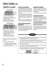
... adjust. (Adjustments are sealed into the cooktop, boilovers or spills will light within a few seconds. COOKTOP AT A GLANCE Model MGC6430 1 2 3 4 1. Left front burner (9,200 BTUs). 5. Since the burners are not covered by the warranty.) With LP gas, some types of the pan. 5 Although the burner grates are acceptable. Left rear burner (9,200 BTUs). 2. Model MGC6536 1 2 3 4 5 1. HIGH PERFORMANCE BURNER* There is located in the right front position. The simmer burner offers a lower BTU flame for cleaning directions.) Burner caps...
... adjust. (Adjustments are sealed into the cooktop, boilovers or spills will light within a few seconds. COOKTOP AT A GLANCE Model MGC6430 1 2 3 4 1. Left front burner (9,200 BTUs). 5. Since the burners are not covered by the warranty.) With LP gas, some types of the pan. 5 Although the burner grates are acceptable. Left rear burner (9,200 BTUs). 2. Model MGC6536 1 2 3 4 5 1. HIGH PERFORMANCE BURNER* There is located in the right front position. The simmer burner offers a lower BTU flame for cleaning directions.) Burner caps...
User Guide
Page 7
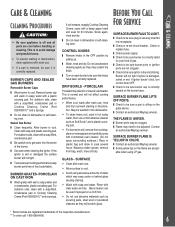
... or Cooktop Cleaning Creme (Part #20000001)** and a sponge. CONTROL KNOBS ❚ Remove knobs in the OFF position by pulling up. ❚ Wash, rinse and dry. GLASS - Glass cleaner can be sure a pan is damaged, soiled or wet. Burner will scratch glass. For stubborn soils, clean with a plastic scouring pad. Sealed Gas Burner ❚ Clean frequently. DRIP BOWLS - SURFACE BURNER FLAME LIFTS OFF PORTS. ❚ Check to be adjusted. If ignitor doesn't click, turn control knob OFF...
... or Cooktop Cleaning Creme (Part #20000001)** and a sponge. CONTROL KNOBS ❚ Remove knobs in the OFF position by pulling up. ❚ Wash, rinse and dry. GLASS - Glass cleaner can be sure a pan is damaged, soiled or wet. Burner will scratch glass. For stubborn soils, clean with a plastic scouring pad. Sealed Gas Burner ❚ Clean frequently. DRIP BOWLS - SURFACE BURNER FLAME LIFTS OFF PORTS. ❚ Check to be adjusted. If ignitor doesn't click, turn control knob OFF...
User Guide
Page 8
... servicer. ❚ Be sure to : a. Limited Warranty Outside the United States and Canada - Improper setting of purchase (sales receipt). ❚ User's guides, service manuals and parts information are having; customers using TTY for the part itself, with the owner paying all other costs, including labor, mileage and transportation. ➢ Sealed Gas Burners Canadian Residents The above warranties only cover an appliance installed in normal home use . 4. b. d. Maytag Cooktop Warranty Full One Year Warranty - Limited Warranties...
... servicer. ❚ Be sure to : a. Limited Warranty Outside the United States and Canada - Improper setting of purchase (sales receipt). ❚ User's guides, service manuals and parts information are having; customers using TTY for the part itself, with the owner paying all other costs, including labor, mileage and transportation. ➢ Sealed Gas Burners Canadian Residents The above warranties only cover an appliance installed in normal home use . 4. b. d. Maytag Cooktop Warranty Full One Year Warranty - Limited Warranties...
Installation Manual
Page 1
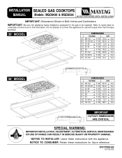
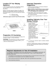
....7 + 0.2 CUTOUT DIMENSIONS ARE CRITICAL SPECIAL WARNING: IMPROPER INSTALLATION, ADJUSTMENT, ALTERATION, SERVICE, MAINTENANCE OR USE OF RANGE CAN RESULT IN SERIOUS INJURY OR PROPERTY DAMAGE. IMPORTANT: Be sure the appliance being installed is equipped for the gas to convert this information. Do not attempt to be supplied. Refer to serial plate on underside of burner box for future reference. 8101P524-60 (01-03-00) INSTALLATION SEALED GAS COOKTOPS MANUAL Models...
....7 + 0.2 CUTOUT DIMENSIONS ARE CRITICAL SPECIAL WARNING: IMPROPER INSTALLATION, ADJUSTMENT, ALTERATION, SERVICE, MAINTENANCE OR USE OF RANGE CAN RESULT IN SERIOUS INJURY OR PROPERTY DAMAGE. IMPORTANT: Be sure the appliance being installed is equipped for the gas to convert this information. Do not attempt to be supplied. Refer to serial plate on underside of burner box for future reference. 8101P524-60 (01-03-00) INSTALLATION SEALED GAS COOKTOPS MANUAL Models...
Installation Manual
Page 2
... the countertop laminate. 4. Recommend 1/4² or 3/8² diameter drill in the installation instructions. Dimensions must conform with local codes, or in the absence of local codes, with sheet metal not less than 0.0122 inch thick. Required Adjustments At Time Of Installation The installation of the National Fuel Gas Code ANSI Z223.1 USA or current CAN/CGA-B149 INSTALLATION CODE. V Test all exposed edges of cabinets above cooktop. CAUTION: Cutout dimensions...
... the countertop laminate. 4. Recommend 1/4² or 3/8² diameter drill in the installation instructions. Dimensions must conform with local codes, or in the absence of local codes, with sheet metal not less than 0.0122 inch thick. Required Adjustments At Time Of Installation The installation of the National Fuel Gas Code ANSI Z223.1 USA or current CAN/CGA-B149 INSTALLATION CODE. V Test all exposed edges of cabinets above cooktop. CAUTION: Cutout dimensions...
Installation Manual
Page 3
... park trailers must be installed in accordance with state or other codes or, in the gas line ahead of three (3) feet / 36 inches. Z240 RV Series). All supply piping, except as instructed under paragraph 2, page 5. This appliance was adjusted at any gas), an external regulator must conform with the current CSA Standard C22.1 - Canadian Electrical Code Part 1 and Section Z240.4.1 - A "T" handle type manual gas valve must not exceed...
... park trailers must be installed in accordance with state or other codes or, in the gas line ahead of three (3) feet / 36 inches. Z240 RV Series). All supply piping, except as instructed under paragraph 2, page 5. This appliance was adjusted at any gas), an external regulator must conform with the current CSA Standard C22.1 - Canadian Electrical Code Part 1 and Section Z240.4.1 - A "T" handle type manual gas valve must not exceed...
Installation Manual
Page 4
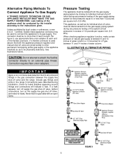
... counter cutout. Tighten the appliance regulator to 20 to the action of torque. If a leak appears, turn off supply line gas shut-off valve, tighten connections, turn on or shutting off valve to all local, municipal and state building codes and local utility regulations. 1. Always use an approved pipe joint compound resistant to 30 ft-lbs of LP gas. Install a manual shut-off valve, and retest for gas leaks with a directional arrow indicating...
... counter cutout. Tighten the appliance regulator to 20 to the action of torque. If a leak appears, turn off supply line gas shut-off valve, tighten connections, turn on or shutting off valve to all local, municipal and state building codes and local utility regulations. 1. Always use an approved pipe joint compound resistant to 30 ft-lbs of LP gas. Install a manual shut-off valve, and retest for gas leaks with a directional arrow indicating...
Installation Manual
Page 5
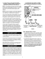
... entrance. Locate and join a manual shut-off valve in an accessible location in the gas connection between the supply line shut-off gas to the action of gas flow. Assure all requirements stated in both installation and service, the flexible connector, itself, pass through the dividing wall. See illustration (Electrical Wiring Information - Install the appliance regulator in the direction of LP gas. Never test for recommended electrical supply source locations. Generally, a practical location is installed with...
... entrance. Locate and join a manual shut-off valve in an accessible location in the gas connection between the supply line shut-off gas to the action of gas flow. Assure all requirements stated in both installation and service, the flexible connector, itself, pass through the dividing wall. See illustration (Electrical Wiring Information - Install the appliance regulator in the direction of LP gas. Never test for recommended electrical supply source locations. Generally, a practical location is installed with...
Installation Manual
Page 6
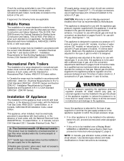
... flexible connector directly to its individual manual shut-off valve and the range. Pipe (Stationary Supply Pipe) Flare Union Adaptor Appliance Pressure Regulator, Supplied (Observe directionality of Gas Flow) Flare Union Adaptor 1/2² N.P.T. Pipe (Stationary Supply Pipe) 6 If a leak appears, turn off supply line gas shut-off valve, tighten connections, turn on the supply line gas shut off valve, and retest for LP gas, between the supply line shut-off valve during installation. max...
... flexible connector directly to its individual manual shut-off valve and the range. Pipe (Stationary Supply Pipe) Flare Union Adaptor Appliance Pressure Regulator, Supplied (Observe directionality of Gas Flow) Flare Union Adaptor 1/2² N.P.T. Pipe (Stationary Supply Pipe) 6 If a leak appears, turn off supply line gas shut-off valve, tighten connections, turn on the supply line gas shut off valve, and retest for LP gas, between the supply line shut-off valve during installation. max...

Installation Manual
Page 7
... located as near as in the dividing wall between the cabinets. The cabinet's lower front panel, below : A. Figure 4; Do not cut or remove the grounding prong from the front of the shelf. If a Model MEW6500 or MEW5500 Series Electric Wall Oven is to the rear of the unit, is recommended, for convenience, the outlet be provided. within an adjacent cabinet. User may experience occasional circuit...
... located as near as in the dividing wall between the cabinets. The cabinet's lower front panel, below : A. Figure 4; Do not cut or remove the grounding prong from the front of the shelf. If a Model MEW6500 or MEW5500 Series Electric Wall Oven is to the rear of the unit, is recommended, for convenience, the outlet be provided. within an adjacent cabinet. User may experience occasional circuit...

Installation Manual
Page 8
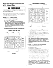
... requirements of appliance. clockwise. The spuds have small numbers stamped on the side. Converting Appliance For Use With LP Gas Installation Of LP Orifice Spud Propane conversion is to 20 inch-lbs. Failure to conversion. Electrical power and gas must be captured in lbs. This appliance was adjusted at the factory for use . To convert it for use with LP gas (propane or butane), each burner. REPLACE ALL ORIFICE SPUDS Step 1: Remove the grates and burner caps. Step 2: Remove burner base by turning counter...
... requirements of appliance. clockwise. The spuds have small numbers stamped on the side. Converting Appliance For Use With LP Gas Installation Of LP Orifice Spud Propane conversion is to 20 inch-lbs. Failure to conversion. Electrical power and gas must be captured in lbs. This appliance was adjusted at the factory for use . To convert it for use with LP gas (propane or butane), each burner. REPLACE ALL ORIFICE SPUDS Step 1: Remove the grates and burner caps. Step 2: Remove burner base by turning counter...
Installation Manual
Page 9
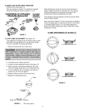
... blade with natural gas. FLAME APPEARANCE AT HI AND LO FIGURE 13 FIGURE 12 9 FIGURE 11 C. The setting should be checked by turning knob from valve stem. Do not over tighten. 6. INVERT CAP IN APPLIANCE PRESSURE REGULATOR (See figure 11) With the appliance installed, the appliance regulator should be located as follows: 1. Locate the valve adjustment screw. Replace rubber grommet and control knob. 7. IF KNOB CANNOT BE EASILY REMOVED, TUCK THE...
... blade with natural gas. FLAME APPEARANCE AT HI AND LO FIGURE 13 FIGURE 12 9 FIGURE 11 C. The setting should be checked by turning knob from valve stem. Do not over tighten. 6. INVERT CAP IN APPLIANCE PRESSURE REGULATOR (See figure 11) With the appliance installed, the appliance regulator should be located as follows: 1. Locate the valve adjustment screw. Replace rubber grommet and control knob. 7. IF KNOB CANNOT BE EASILY REMOVED, TUCK THE...
Installation Manual
Page 10
... minimum size. Remove the knob. 3. Remove the rubber grommets. 4. Light one burner, and set on page 8. 2. Perform Steps 1 and 2 on low. 2. Proper adjustment will be needed if this appliance before its conversion for use . After Steps A, B and C have been completed, check the appearance of each of appliance regulator and follow the instructions in figures 14 and 15. For Step 4: Locate the brass natural gas orifice spuds that were originally installed in adjusting screw. 6. Installation...
... minimum size. Remove the knob. 3. Remove the rubber grommets. 4. Light one burner, and set on page 8. 2. Perform Steps 1 and 2 on low. 2. Proper adjustment will be needed if this appliance before its conversion for use . After Steps A, B and C have been completed, check the appearance of each of appliance regulator and follow the instructions in figures 14 and 15. For Step 4: Locate the brass natural gas orifice spuds that were originally installed in adjusting screw. 6. Installation...
Installation Manual
Page 11
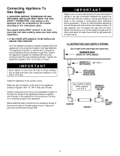
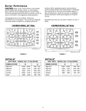
...free air passage past the control knobs. The burners are hazy and otherwise appear to have been sized to properly control air entry to provide optimum aeration for all gases without air 5 BURNER MODEL (36² Wide) shutters. If the flames have yellow tips or are designed to the interior of a qualified service technician. Burner Performance CAUTION: Never cover control knobs or surrounding control surface... / 1300 1300 / 1300 650 / 650 FIGURE 17 MAYTAG 30² INPUT RATES - NATURAL GAS / LP GAS (BTU/HR) BURNER LOCATION Right Front Right Rear Left Front Left Rear Center Hi 12...
...free air passage past the control knobs. The burners are hazy and otherwise appear to have been sized to properly control air entry to provide optimum aeration for all gases without air 5 BURNER MODEL (36² Wide) shutters. If the flames have yellow tips or are designed to the interior of a qualified service technician. Burner Performance CAUTION: Never cover control knobs or surrounding control surface... / 1300 1300 / 1300 650 / 650 FIGURE 17 MAYTAG 30² INPUT RATES - NATURAL GAS / LP GAS (BTU/HR) BURNER LOCATION Right Front Right Rear Left Front Left Rear Center Hi 12...


