Installation Manual
Page 9
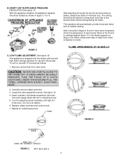
...completed correctly. Locate the valve adjustment screw. Turn the adjusting screw clockwise until tight (5-7 in adjusting screw. 5. Repeat for use with natural gas. FIGURE 11 C. FLAME APPEARANCE AT HI AND LO FIGURE 13 FIGURE 12 9 Carefully remove rubber grommet. 3. This operation will automatically provide.... Do not over tighten. 6. B. The setting should be located as follows: 1. If the flames appear too large or too small, review each burner flame at medium setting. CAUTION: NEVER USE A METAL BLADE TO PRY KNOB OFF. To set for remaining burners. IF KNOB ...
...completed correctly. Locate the valve adjustment screw. Turn the adjusting screw clockwise until tight (5-7 in adjusting screw. 5. Repeat for use with natural gas. FIGURE 11 C. FLAME APPEARANCE AT HI AND LO FIGURE 13 FIGURE 12 9 Carefully remove rubber grommet. 3. This operation will automatically provide.... Do not over tighten. 6. B. The setting should be located as follows: 1. If the flames appear too large or too small, review each burner flame at medium setting. CAUTION: NEVER USE A METAL BLADE TO PRY KNOB OFF. To set for remaining burners. IF KNOB ...