Installation Manual
Page 1
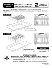
... 1/4 + 1/16 38.7 + 0.2 CUTOUT DIMENSIONS ARE CRITICAL SPECIAL WARNING: IMPROPER INSTALLATION, ADJUSTMENT, ALTERATION, SERVICE, MAINTENANCE OR USE OF RANGE CAN RESULT IN SERIOUS INJURY OR PROPERTY DAMAGE. Refer to convert this information. INSTALLATION SEALED GAS COOKTOPS MANUAL Models: MGC5430 & MGC5536 403 WEST FOURTH STREET, NORTH · NEWTON, IA 50208 IMPORTANT: Dimensions Shown in Both Inches and Centimeters. Do not attempt to serial plate on underside of burner box for future...
... 1/4 + 1/16 38.7 + 0.2 CUTOUT DIMENSIONS ARE CRITICAL SPECIAL WARNING: IMPROPER INSTALLATION, ADJUSTMENT, ALTERATION, SERVICE, MAINTENANCE OR USE OF RANGE CAN RESULT IN SERIOUS INJURY OR PROPERTY DAMAGE. Refer to convert this information. INSTALLATION SEALED GAS COOKTOPS MANUAL Models: MGC5430 & MGC5536 403 WEST FOURTH STREET, NORTH · NEWTON, IA 50208 IMPORTANT: Dimensions Shown in Both Inches and Centimeters. Do not attempt to serial plate on underside of burner box for future...
Installation Manual
Page 2
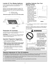
... measured and cut accurately to insure smooth edges and prevent corner cracking. Chamfer all exposed edges of cabinets installed above cooktop for gas leaks. Radius corners of the countertop laminate. 4. V Test all external connections for storage space to prevent damage from combustible materials such as reaching over open flame. Important Preparation Suggestions 1. V Test all electrical connections. 2 Minimum horizontal clearance between cooking surface and construction above the cooking surface...
... measured and cut accurately to insure smooth edges and prevent corner cracking. Chamfer all exposed edges of cabinets installed above cooktop for gas leaks. Radius corners of the countertop laminate. 4. V Test all external connections for storage space to prevent damage from combustible materials such as reaching over open flame. Important Preparation Suggestions 1. V Test all electrical connections. 2 Minimum horizontal clearance between cooking surface and construction above the cooking surface...
Installation Manual
Page 3
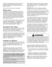
...² models) on natural gas or, if converted for use with the appliance gas pressure regulator supplied with LP gas (propane or butane), 10 inches water column. NOTE: In Canada, gas utilization codes prohibit use an approved pipe joint compound resistant to the action of local codes, with local codes or, in Canada, current CSA Standard C22.1 Canadian Electrical Code, Part 1. Canadian Electrical Code Part 1 and Section Z240.4.1 - Installation Requirements for R.V.'s (CSA Standard CAN/CSA - Installation Of...
...² models) on natural gas or, if converted for use with the appliance gas pressure regulator supplied with LP gas (propane or butane), 10 inches water column. NOTE: In Canada, gas utilization codes prohibit use an approved pipe joint compound resistant to the action of local codes, with local codes or, in Canada, current CSA Standard C22.1 Canadian Electrical Code, Part 1. Canadian Electrical Code Part 1 and Section Z240.4.1 - Installation Requirements for R.V.'s (CSA Standard CAN/CSA - Installation Of...
Installation Manual
Page 4
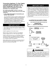
... appliance pressure regulator with 1/2² NPT male pipe threads. Make the gas connection to the gas supply source. Install a manual shut-off valve in an accessible location in the gas connection between the supply line shut-off valve to the inlet of torque. Make additional pipe connections as necessary ahead of turning on the supply line gas shut off gas to the action of gas flow. Include gas fittings and joints in its counter cutout...
... appliance pressure regulator with 1/2² NPT male pipe threads. Make the gas connection to the gas supply source. Install a manual shut-off valve in an accessible location in the gas connection between the supply line shut-off valve to the inlet of torque. Make additional pipe connections as necessary ahead of turning on the supply line gas shut off gas to the action of gas flow. Include gas fittings and joints in its counter cutout...
Installation Manual
Page 5
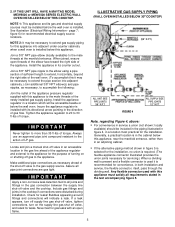
... adjacent under-counter cabinetry when a wall oven is in both installation and service, the flexible connector, itself, pass through the dividing wall. Check for convenience, in the cabinet below the wall oven. 2. NOTE 1: This appliance and its counter cutout. If a leak appears, turn off supply line gas shut-off valve, tighten connections, turn on or shutting off valve and the cooktop. Any flexible connector used it may be installed before the wall oven is recommended...
... adjacent under-counter cabinetry when a wall oven is in both installation and service, the flexible connector, itself, pass through the dividing wall. Check for convenience, in the cabinet below the wall oven. 2. NOTE 1: This appliance and its counter cutout. If a leak appears, turn off supply line gas shut-off valve, tighten connections, turn on or shutting off valve and the cooktop. Any flexible connector used it may be installed before the wall oven is recommended...
Installation Manual
Page 6
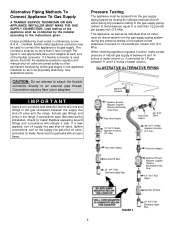
... GAS SUPPLY CONNECTION. Unless prohibited by the installer according to the instructions given. If a flexible connector is between 6 and 14 inches of water column or, if converted for gas leaks with an open flame. Connection requires flare union adapters. max.) Flare Union Adaptor 3/8² N.P.T. Elbow 3/8² N.P.T. Certified, flexible metal appliance connector may be used assure that both the appliance pressure regulator and manual shut-off valve...
... GAS SUPPLY CONNECTION. Unless prohibited by the installer according to the instructions given. If a flexible connector is between 6 and 14 inches of water column or, if converted for gas leaks with an open flame. Connection requires flare union adapters. max.) Flare Union Adaptor 3/8² N.P.T. Elbow 3/8² N.P.T. Certified, flexible metal appliance connector may be used assure that both the appliance pressure regulator and manual shut-off valve...
Installation Manual
Page 7
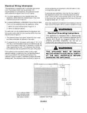
... or right adjacent cabinet, a clearance hole, as in A or B, below the oven, must be provided in the corresponding right wall. A grounded outlet must be mounted within either : 1. If a Model MEW6500 or MEW5500 Series Electric Wall Oven is to be plugged directly into a properly grounded receptacle. If a wall oven is to be installed below this appliance and the counter units outlet is to be made removable for your...
... or right adjacent cabinet, a clearance hole, as in A or B, below the oven, must be provided in the corresponding right wall. A grounded outlet must be mounted within either : 1. If a Model MEW6500 or MEW5500 Series Electric Wall Oven is to be plugged directly into a properly grounded receptacle. If a wall oven is to be installed below this appliance and the counter units outlet is to be made removable for your...
Installation Manual
Page 8
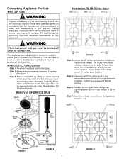
... number codes the orifice diameter and its correct burner location. Step 7: Save the orifices removed from the appliance for use . 0.64 0.91 FIGURE 7 Orifice Spud FIGURE 8 0.91 0.97 FIGURE 10 8 Converting Appliance For Use With LP Gas WARNING Propane conversion is to be performed by a MAYTAG AUTHORIZED SERVICER (or other qualified agency) in accordance with natural gas. REPLACE ALL ORIFICE SPUDS Step 1: Remove the grates and burner caps. Tighten screws (do not cross thread) to 20 inch...
... number codes the orifice diameter and its correct burner location. Step 7: Save the orifices removed from the appliance for use . 0.64 0.91 FIGURE 7 Orifice Spud FIGURE 8 0.91 0.97 FIGURE 10 8 Converting Appliance For Use With LP Gas WARNING Propane conversion is to be performed by a MAYTAG AUTHORIZED SERVICER (or other qualified agency) in accordance with natural gas. REPLACE ALL ORIFICE SPUDS Step 1: Remove the grates and burner caps. Tighten screws (do not cross thread) to 20 inch...
Installation Manual
Page 9
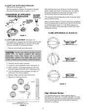
... necessary. 9 FLAME APPEARANCE AT HI AND LO KNOB FIGURE 13 ADJUSTMENT SCREW KNOB HOLE (KNOB AND GROMMET REMOVED) FIGURE 12 High Altitude Notice The specified gas burner ratings typically apply to elevations up to achieve satisfactory operation. After Conversion Steps A, B and C have been completed, check the appearance of minimum size. CONVERSION OF APPLIANCE PRESSURE REGULATOR After adjusting the screw the burner should be reduced to 2000 feet. Locate the valve adjustment screw. B.
... necessary. 9 FLAME APPEARANCE AT HI AND LO KNOB FIGURE 13 ADJUSTMENT SCREW KNOB HOLE (KNOB AND GROMMET REMOVED) FIGURE 12 High Altitude Notice The specified gas burner ratings typically apply to elevations up to achieve satisfactory operation. After Conversion Steps A, B and C have been completed, check the appearance of minimum size. CONVERSION OF APPLIANCE PRESSURE REGULATOR After adjusting the screw the burner should be reduced to 2000 feet. Locate the valve adjustment screw. B.
Installation Manual
Page 10
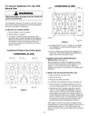
... unit back to natural gas. Remove the knob. 3. To Convert Appliance For Use With Natural Gas 4 BURNER MODEL (30² WIDE) 1.10 1.55 WARNING Electrical power and gas must be turned off prior to conversion. Light one burner, and set on page 9, under C. REPLACE ALL ORIFICE SPUDS. 1. A. Starting from the appliance for use with LP gas. Perform Step 3 on each of appliance regulator and follow the instructions in adjusting screw. 6. Save the orifices removed from the LP position...
... unit back to natural gas. Remove the knob. 3. To Convert Appliance For Use With Natural Gas 4 BURNER MODEL (30² WIDE) 1.10 1.55 WARNING Electrical power and gas must be turned off prior to conversion. Light one burner, and set on page 9, under C. REPLACE ALL ORIFICE SPUDS. 1. A. Starting from the appliance for use with LP gas. Perform Step 3 on each of appliance regulator and follow the instructions in adjusting screw. 6. Save the orifices removed from the LP position...
Installation Manual
Page 11
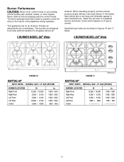
... and otherwise appear to have been sized to properly control air entry to provide optimum aeration for all gases without air 5 BURNER MODEL (36² Wide) shutters. Primary air adjustments are as shown in figures 16 and 17 below. 4 BURNER MODEL (30² Wide) FIGURE 16 MAYTAG 36² INPUT RATES - Specified input rates are unnecessary. NATURAL GAS / LP GAS (BTU/HR) BURNER LOCATION Right Front Right Rear Left Front...
... and otherwise appear to have been sized to properly control air entry to provide optimum aeration for all gases without air 5 BURNER MODEL (36² Wide) shutters. Primary air adjustments are as shown in figures 16 and 17 below. 4 BURNER MODEL (30² Wide) FIGURE 16 MAYTAG 36² INPUT RATES - Specified input rates are unnecessary. NATURAL GAS / LP GAS (BTU/HR) BURNER LOCATION Right Front Right Rear Left Front...
Installation Manual
Page 12
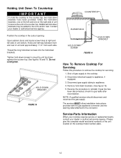
... model and serial numbers of unit and approximately 1 1/4² from each side. Holes are half way between front and rear of the unit located on the left side of unit to secure the unit to snug the unit top down brackets have been provided. HOLD-DOWN BRACKET FIGURE 18 COUNTERTOP BURNER BOX HOLD-DOWN BRACKET HOLD-DOWN SCREW FIGURE 19 How To Remove Cooktop For Servicing...
... model and serial numbers of unit and approximately 1 1/4² from each side. Holes are half way between front and rear of the unit located on the left side of unit to secure the unit to snug the unit top down brackets have been provided. HOLD-DOWN BRACKET FIGURE 18 COUNTERTOP BURNER BOX HOLD-DOWN BRACKET HOLD-DOWN SCREW FIGURE 19 How To Remove Cooktop For Servicing...


