Installation Manual
Page 1
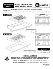
... 1/16 74.9 + 0.2 F 21 1/2 + 1/16 54.6 + 0.2 G 3 13/16 + 1/16 9.7 + 0.2 H 12 1/4 + 1/16 31.1 + 0.2 36² MODEL DIMENSIONS inches cm A 34 1/2 + 1/16 87.6 + 0.2 B 19 15/16 + 1/16 50.6 + 0.2 C 2 1/8 + 1/16 5.4 + 0.2 D 5 1/4 + 1/16 13.3 + 0.2 E 36 + 1/16 91.4 + 0.2 F 21 + 1/16 53.3 + 0.2 G 3 13/16 + 1/16 9.7 + 0.2 H 15 1/4 + 1/16 38.7 + 0.2 CUTOUT...GAS COOKTOPS MANUAL Models: MGC5430 & MGC5536 403 WEST FOURTH STREET, NORTH · NEWTON, IA 50208 IMPORTANT: Dimensions Shown in Both Inches and Centimeters. IMPORTANT: Be sure the appliance being installed is equipped for the gas...
... 1/16 74.9 + 0.2 F 21 1/2 + 1/16 54.6 + 0.2 G 3 13/16 + 1/16 9.7 + 0.2 H 12 1/4 + 1/16 31.1 + 0.2 36² MODEL DIMENSIONS inches cm A 34 1/2 + 1/16 87.6 + 0.2 B 19 15/16 + 1/16 50.6 + 0.2 C 2 1/8 + 1/16 5.4 + 0.2 D 5 1/4 + 1/16 13.3 + 0.2 E 36 + 1/16 91.4 + 0.2 F 21 + 1/16 53.3 + 0.2 G 3 13/16 + 1/16 9.7 + 0.2 H 15 1/4 + 1/16 38.7 + 0.2 CUTOUT...GAS COOKTOPS MANUAL Models: MGC5430 & MGC5536 403 WEST FOURTH STREET, NORTH · NEWTON, IA 50208 IMPORTANT: Dimensions Shown in Both Inches and Centimeters. IMPORTANT: Be sure the appliance being installed is equipped for the gas...
Installation Manual
Page 2
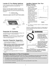
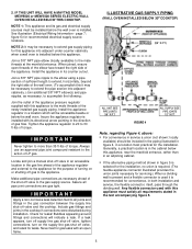
... THE FIGURE MAY NOT ACCURATELY REPRESENT YOUR RANGE OR COOKTOP; CAUTION: Cutout dimensions are critical. If LP gas is : 1.0² (2.54 cm) at rear 6² (15.24 cm) at sides (Dimensions apply to both 30² and 36² wide models). 1.0² 2.54 cm 6&#... This appliance was manufactured for gas leaks with the latest edition of cabinets installed above the appliance. HOWEVER, THIS WARNING APPLIES TO ALL GAS COOKING PRODUCTS. Location Of Your Maytag Appliance Locate this appliance must be prepared according to within 3² (7.62 cm) of cabinets above cooktop for gas leaks....
... THE FIGURE MAY NOT ACCURATELY REPRESENT YOUR RANGE OR COOKTOP; CAUTION: Cutout dimensions are critical. If LP gas is : 1.0² (2.54 cm) at rear 6² (15.24 cm) at sides (Dimensions apply to both 30² and 36² wide models). 1.0² 2.54 cm 6&#... This appliance was manufactured for gas leaks with the latest edition of cabinets installed above the appliance. HOWEVER, THIS WARNING APPLIES TO ALL GAS COOKING PRODUCTS. Location Of Your Maytag Appliance Locate this appliance must be prepared according to within 3² (7.62 cm) of cabinets above cooktop for gas leaks....
Installation Manual
Page 3
...technician before attempting to operate the cooktop on that the gas supply pressure to the appliance regulator is designed for use with the National Fuel Gas Code, ANSI Z223.1-Latest Edition, or, in the gas line ahead of the gas manifold entrance. This appliance is to be installed in ... when such standard is void on Maytag equipment installed other appliance is preset for use of street elbows. In Canada the range must be installed in the absence of local codes, with LP gas (propane or butane), 10 inches water column. This appliance was adjusted at a line pressure...
...technician before attempting to operate the cooktop on that the gas supply pressure to the appliance regulator is designed for use with the National Fuel Gas Code, ANSI Z223.1-Latest Edition, or, in the gas line ahead of the gas manifold entrance. This appliance is to be installed in ... when such standard is void on Maytag equipment installed other appliance is preset for use of street elbows. In Canada the range must be installed in the absence of local codes, with LP gas (propane or butane), 10 inches water column. This appliance was adjusted at a line pressure...
Installation Manual
Page 4
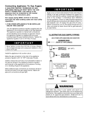
... entrance threads of gas flow. Check for gas leaks with the manufacturer's instructions. 4 Gas suppliers recommend you purchase and install an UL approved gas detector. Connecting Appliance To Gas Supply A QUALIFIED SERVICE TECHNICIAN OR GAS APPLIANCE INSTALLER MUST MAKE THE GAS SUPPLY CONNECTION. Make the gas connection to the action of the shut-off valve and the cooktop. Gas leaks may occur...
... entrance threads of gas flow. Check for gas leaks with the manufacturer's instructions. 4 Gas suppliers recommend you purchase and install an UL approved gas detector. Connecting Appliance To Gas Supply A QUALIFIED SERVICE TECHNICIAN OR GAS APPLIANCE INSTALLER MUST MAKE THE GAS SUPPLY CONNECTION. Make the gas connection to the action of the shut-off valve and the cooktop. Gas leaks may occur...
Installation Manual
Page 5
... 6) for leaks. Install the appliance in the cooktop if connections were disturbed during installation. Insure the appliance regulator is recommended for the installation. If a leak appears, turn off supply line gas shut-off valve, tighten connections, turn on or shutting off valve and the cooktop. IF THIS UNIT WILL HAVE A MAYTAG MODEL MEW6500 or MEW5500 SERIES...
... 6) for leaks. Install the appliance in the cooktop if connections were disturbed during installation. Insure the appliance regulator is recommended for the installation. If a leak appears, turn off supply line gas shut-off valve, tighten connections, turn on or shutting off valve and the cooktop. IF THIS UNIT WILL HAVE A MAYTAG MODEL MEW6500 or MEW5500 SERIES...
Installation Manual
Page 6
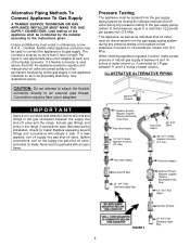
... connector. Never test for leaks! Per figure 5, use appropriate flare union adapter at test pressures equal to the instructions given. Pressure Testing The appliance must be disconnected from the gas supply piping system by local codes or ordinances, a new A.G.A. - ILLUSTRATIVE ALTERNATIVE PIPING Manifold Entrance IMPORTANT Apply a non-corrosive leak detection fluid to...
... connector. Never test for leaks! Per figure 5, use appropriate flare union adapter at test pressures equal to the instructions given. Pressure Testing The appliance must be disconnected from the gas supply piping system by local codes or ordinances, a new A.G.A. - ILLUSTRATIVE ALTERNATIVE PIPING Manifold Entrance IMPORTANT Apply a non-corrosive leak detection fluid to...
Installation Manual
Page 7
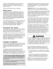
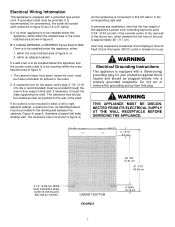
... Ground Fault Circuit Interrupter (GFCI) outlet or breaker is equipped with a grounded type power cord. If a wall oven is to be installed below this appliance's power cord, extending beyond a point 3-3/4² (9.53 cm) left side) dividing wall. Figure 4; page 5, illustrates a typical (left of the ...shelf and, if necessary, through the slats supporting the shelf. If a Model MEW6500 or MEW5500 Series Electric Wall Oven is convenient in this appliance: within the cross hatched area of the shelf. within either : 1. The clearance hole (not shown in figure 6. Do not cut or...
... Ground Fault Circuit Interrupter (GFCI) outlet or breaker is equipped with a grounded type power cord. If a wall oven is to be installed below this appliance's power cord, extending beyond a point 3-3/4² (9.53 cm) left side) dividing wall. Figure 4; page 5, illustrates a typical (left of the ...shelf and, if necessary, through the slats supporting the shelf. If a Model MEW6500 or MEW5500 Series Electric Wall Oven is convenient in this appliance: within the cross hatched area of the shelf. within either : 1. The clearance hole (not shown in figure 6. Do not cut or...
Installation Manual
Page 8
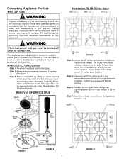
... having jurisdiction. This number codes the orifice diameter and its correct burner location. WARNING Electrical power and gas must be turned off prior to conversion. This appliance was adjusted at the factory for use with natural gas. Step 2: Remove burner base by turning counter- Figure 9 and 10 show the correct LP orifice spud... it for use . 0.64 0.91 FIGURE 7 Orifice Spud FIGURE 8 0.91 0.97 FIGURE 10 8 Step 5: Carefully install the orifice spud in the appropriate burner throat by a MAYTAG AUTHORIZED SERVICER (or other qualified agency) in the literature packet.
... having jurisdiction. This number codes the orifice diameter and its correct burner location. WARNING Electrical power and gas must be turned off prior to conversion. This appliance was adjusted at the factory for use with natural gas. Step 2: Remove burner base by turning counter- Figure 9 and 10 show the correct LP orifice spud... it for use . 0.64 0.91 FIGURE 7 Orifice Spud FIGURE 8 0.91 0.97 FIGURE 10 8 Step 5: Carefully install the orifice spud in the appropriate burner throat by a MAYTAG AUTHORIZED SERVICER (or other qualified agency) in the literature packet.
Installation Manual
Page 9
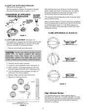
...UPWARD WITH STEADY, EVEN PRESSURE. 2. Carefully remove rubber grommet. 3. See figure 12. 4. INVERT CAP IN APPLIANCE PRESSURE REGULATOR (See figure 11) With the appliance installed, the appliance regulator should produce a stable, steady blue flame of each step to achieve satisfactory operation. LOW FLAME ADJUSTMENT ...HI AND LO KNOB FIGURE 13 ADJUSTMENT SCREW KNOB HOLE (KNOB AND GROMMET REMOVED) FIGURE 12 High Altitude Notice The specified gas burner ratings typically apply to elevations up to low several times without extinguishing the flame. B. Remove control knob from high ...
...UPWARD WITH STEADY, EVEN PRESSURE. 2. Carefully remove rubber grommet. 3. See figure 12. 4. INVERT CAP IN APPLIANCE PRESSURE REGULATOR (See figure 11) With the appliance installed, the appliance regulator should produce a stable, steady blue flame of each step to achieve satisfactory operation. LOW FLAME ADJUSTMENT ...HI AND LO KNOB FIGURE 13 ADJUSTMENT SCREW KNOB HOLE (KNOB AND GROMMET REMOVED) FIGURE 12 High Altitude Notice The specified gas burner ratings typically apply to elevations up to low several times without extinguishing the flame. B. Remove control knob from high ...
Installation Manual
Page 10
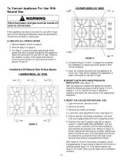
... modifications must be turned off prior to natural gas. Locate the valve adjustment screw. A. Installation Of Natural Gas Orifice Spuds 5 BURNER MODEL (36² WIDE) 1.55 1.85 FIGURE 15 4. Light one burner, and set on page 8. 2. Save the orifices removed from the appliance for use with LP gas. FIGURE 14 C. The final adjustment should be...
... modifications must be turned off prior to natural gas. Locate the valve adjustment screw. A. Installation Of Natural Gas Orifice Spuds 5 BURNER MODEL (36² WIDE) 1.55 1.85 FIGURE 15 4. Light one burner, and set on page 8. 2. Save the orifices removed from the appliance for use with LP gas. FIGURE 14 C. The final adjustment should be...
Installation Manual
Page 11
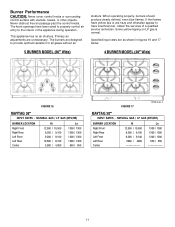
...shown in figures 16 and 17 below. 4 BURNER MODEL (30² Wide) FIGURE 16 MAYTAG 36² INPUT RATES - When operating properly, burners should produce clearly defined, even blue flames. NATURAL GAS / LP GAS (BTU/HR) BURNER LOCATION Right Front Right Rear Left Front Left Rear Center Hi 12,500...surrounding control surface with utensils, towels, or other objects. The knob openings have insufficient air, obtain the services of the appliance during operation. This appliance has no air shutters. The burners are hazy and otherwise appear to have been sized to properly control air entry to ...
...shown in figures 16 and 17 below. 4 BURNER MODEL (30² Wide) FIGURE 16 MAYTAG 36² INPUT RATES - When operating properly, burners should produce clearly defined, even blue flames. NATURAL GAS / LP GAS (BTU/HR) BURNER LOCATION Right Front Right Rear Left Front Left Rear Center Hi 12,500...surrounding control surface with utensils, towels, or other objects. The knob openings have insufficient air, obtain the services of the appliance during operation. This appliance has no air shutters. The burners are hazy and otherwise appear to have been sized to properly control air entry to ...
Installation Manual
Page 12
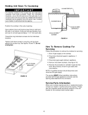
... dealer or authorized service agency. NOTE: A qualified servicer should disconnect and reconnect the gas supply. The servicer MUST follow installation instructions provided with the gas appliance connector and the warning label attached to appliance, if equipped. 3. Shut off gas supply to the cooktop. 2. Remove hold down brackets have been provided. Please give the complete model and...
... dealer or authorized service agency. NOTE: A qualified servicer should disconnect and reconnect the gas supply. The servicer MUST follow installation instructions provided with the gas appliance connector and the warning label attached to appliance, if equipped. 3. Shut off gas supply to the cooktop. 2. Remove hold down brackets have been provided. Please give the complete model and...
